Design and Analysis of Progressive Die for Chain Link Plate
Md Inaithul Rehaman#1, P Satish Reddy#2, Matta Manoj#3, N.Guru Murthy#4 ME Department, Prasiddha College of Engg and Technology, Anathavaram
1[email protected],2[email protected],3[email protected],4[email protected]
Abstract- In sheet metal manufacturing Design and development of different components is one of the important phase. This is a highly complex process and leads to to various uncertainties. These uncertainties can induce heavy manufacturing losses through premature die failure, final part geometric distortion and production risk.
Identification of these uncertainties and quantifying them is a challenging job for the designer and FEM based modeling is a very effective tool to overcome the above uncertainties.
Progressive die components are modeled in CATIA with selected dimensions for chain link plate. Finite element analysis is conducted for Progressive die obtaining deformation and stresses by using ANSYS software. Results obtained from theoretical analysis are in good agreement with empirical equation used in commercial design however ANSYS provides more accurate results compared to the available approximate empirical equations.
Keywords- Progressive die, chain link plate, ANSYS.
I. Introduction
The design and manufacture of press tools, or punches and dies, is a branch of production technology that has extended into many lines of engineering manufacture over the past seventy years. There is no doubt that the accuracy achieved by new ideas in design and construction applied by the press tool designer, coupled with increased speed and rigidity of the presses etc, used have all contributed toward maintaining this form of metal tooling well to the force as a means of obtaining pleasing, yet
strong, durable articles that can withstand severe day-to-day usage.
More and more it has become the practice to produce from sheet metal by some form of pressing process, work pieces that would have been made from bar, forging or casting two or three decades ago. Also, the handling of both strip material and semi-finished components has assumed an importance simply because fast and efficient movement means cheap products from operators who do not suffer fatigue from the handling of awkward or heavy components. However, it should not be forgotten that press design has made many advances in recent years in common with, for example, the machine tool industry, and machines are now available that are capable of withstanding the heavy stresses set up in many modern production process.
II. Types of Cutting Tools
Progressive Tools
Combination Tools
Compound Tools
Progressive Tools- Progressive tool performs two or more operations at different stages in each stroke. The stock strip is advanced through a series of stations that form one or more distinct press working operations on the strip to get the component.
drawing and embossing etc. The most common type of combination dies blanks and draws a part.
Compound Tools- Similar to a progressive tools, a compound tool also produce blanks having pierced holes but the difference being that the former performance the operations at more than one station where as the later performs both the operations simultaneously at the same station. The conventional positions of the blanking punch and die are inverted. The blanking punch being clamped to the die shoe forms part of the bottom tool, whereas, the blanking die being clamped to the die head forms part of the top tool. The piercing punches assume the conventional position and inside the blanking die opening piercing punches are mounted with a punch holder. Their mating piercing dies are formed in the blanking punch.
III. Elements of Progressive Tools
Die Set- It is one of the basic elements of the stamping industry which can be defined as a sub press unit consisting of a bottom plate and top plate together with guide pillars and bushes by means of which the top and bottom plates are aligned. The purpose of die set is to utilize the entire die assembly.
Top Plate- The upper working member of the tool is called the top plate. The punch assembly including the punch holder and thrust plate is mounted on the top plate. The tool shank, which locates the whole tool centrally with the press ram, is also screwed into the top plate.
Punch Back Plate- While performing the cutting operation, the punch exerts an upward thrust. So a hardened plate to prevent it from digging into the soft-top plate should back up punch. It is made out of case hardened tool steels.
Punch Plate- The punch is usually fixed to a plate with a light press fit. Punch holder holds all types of cutting and non-cutting punches to ensure alignment between punch and die it is made out of ST-42.
Punches- A punch is the male member of a press tool to get a component from the strip. It is made out of good quality alloy steel.
Stripper Plate- When cutting action is over, the punch
moved forward. To facilitate this function one plate is fixed above the die plate. This removes the strip from the punch is called stripper. It guides punches and pilots in this plate to ensure alignment with punch and die.
Die Plate- A die block is defined as the block or plate from which the die profile is cut. It is usually lower member of the tool. It provides cutting edge. The die opening has different designs and the design is selected after looking in the requirements and facilities available.
Bottom Plate- Bottom plate gives cushioning effect to the die as well as provides enough space for the tool to be clamped to the press bed. There may be opening in the base plate, which allows the blank, or slug to fall and clear off from the tool. The die assembly including stripper, all bottom elements are mounted on the bottom plate.
Guide Pillar and Guide Bush-These are very important function in press-tool. Pillar and bushes guide the moving and fixed half of the tool in the press and also it is used to ensure accurate alignment between the punches and die.
Stoppers- After each and every stroke of press the strip has to be fed from one pitch length. This can be accomplished by means of a stopper. The function of the stoppers is to arrest the movement of the strip.
Pressure pads–These are commonly actuated by spring or rubber cylinders. Where more pressure is necessary, the die is usually installed in a press which is equipped with an air cushion. Hydraulic cylinders can also be used to actuate pads when strong pressure is required. In Bending Die, the pressure pad performs the following functions. Which are listed in order of operational sequence.
Ejectors- In the conventional position die is the lower member of the tool (being clamped to die shoe). If the ejection of the blank is achieved by forcing it upwards, the action is known as ejecting. The element of the tool, which ejects the blank, is called an ejector.
Knock out- A mechanism for ejecting blanks on other work from a die commonly located on a slide but may be located on the bolster.
IV Shearing Theory and Action
Shearing is the method of cutting a sheet metal (shear out) without forming chips. The material is stressed from punch and dies side simultaneously in sections that lies parallel to the forces applied by means of shear blades or punches and die.
The cutting action that occurs on blanking or piercing is that similar to that of chip formation by a cutting tool. The punch contracts the work material supported by the die and a pressure build up occurs. The shearing or cutting forces necessary to bring about shearing or rapture of the material depend primarily upon the shearing strength of the material, thickness and cutting length.
Three critical stages of shearing are
Deformation
Penetration
Fracture
The metal is subjected to both tensile and compressive stresses, stretching beyond the elastic limit. Then the Deformation, Penetration and Fracture will takes place.
Fig 1.1 Deformation Stage
Fig 1.2 Penetration Stage
Fig 1.3 Fracture Stage
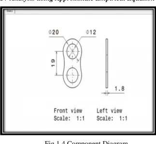
IV Analysis using Approximate Empirical Equation
Fig 1.4 Component Diagram
Cutting Perimeter Stage - 1
Perimeter of Piercing at first stage =x diameter x 2 = x 12 x 2
= 75.4 mm
Cutting perimeter Stage - 2
Perimeter of the profile = x 20 + 19x 2 = 104.176mm
Total shear area = Stage 1 + Stage 2 = 179.576 mm
Cutting Force = Perimeter of the Profile x Thickness x Shear force of the material
= 179.576 x 1.8 x 380= 122829.984 N
THEORETICAL DEFLECTION AND STRESS CALCULATION
DIE BLOCK
Deflection = PL/AE
Where,
P = 80% of cutting force = 0.8 x 122829.984 = 98263.987N
E = modulus of elasticity = 2.1 x 10⁵N/mm2 b = length of bottom plate = 110 mm h = thickness of bottom plate = 25 mm
Deflection, δ = (98263.987 x 25) / (11222.39x 2.1 x
105)
= 0.00104mm
Stress, = P/A
Where, A = cross sectional area
= 98263.987 / (11222.3) = 29.185 N/m2
TOP PLATE
Deflection= PL4/ 384 EI
Where,
P = 80% of cutting force = 0.8 x 122829.984 = 98263.987N
E = modulus of elasticity = 2.1 x 10⁵ N/mm2 I = bh3/12 (moment of inertia) = 2564947.9 mm4
Where,
L= length of bottom plate = 185mm
h = height of bottom plate = 55 mm
Deflection, δ = 0.5564mm
Stress,
Where,
= 315.18MPa
BOTTOM PLATE
Deflection= PL/AE
Where, P = 80% of cutting force = 0.8 x 122829.984 = 98263.987N
E = modulus of elasticity = 2.1 x 10⁵N/mm2 Where,
b = length of bottom plate = 110 mm h = thickness of bottom plate = 30 mm
Deflection, δ = (98263.9x30) / (24302.7x 2.1 x 105) = 0.00061mm
Stress, = P/A
Material Mild steel
Thickness 1.8 mm
Shear Force 380N
Type of Press Mechanical
Type of Die Set Rear Pillar
Method of Feeding Manual
Type of Stroke Fixed
2
bh
h
x
6M
σ
)
2
6x
2
L
(6Lx
12
w
x
A = cross sectional area
= 98263.9 / (24302.7) = 12.13MPa Similarly,
STRIPPER PLATE
= 49.628MPa GUIDE PILLAR
= 146.6 MPa PIERCING PUNCH
=282.99 MPa
BLANKING PUNCH=307.12 MPa
V. Modeling of Progressive Tool
Fig
1.5 Assembled Model of Progressive Tool
MESHING: Meshing is done by using ANSYS workbench shown in fig 4.8 Number of nodes=24527, Number of elements =14515, Element Size=default, Shape = default (tetrahedral), Mesh type = Fine mesh
VI Results and Discussion
Fig 1.6 Deformation in die plate
Fig1.7 Stress in Die Plate
VII Conclusions
1. Maximum deformation 0.00129mm is found at corners
of the die and maximum stress 24.463N/mm2 is
observed at bottom side corners in die plate
2. In Bottom Plate, maximum deformation 0.000702mm
is observed at corners of the bottom plate and
maximum stress 13.34N/mm2 is observed at bottom
side corners.
3. In Top Plate, maximum deformation 0.59866 mm is
observed at free end of the top plate and maximum
4. In Piercing Punch, maximum deformation 0.0333mm
is observed at free end of the piercing punch and
maximum stress 302.80N/mm2 is observed at nearer
to fixed support.
5. Maximum deformation 0.01599 mm is found at free
end of the blanking punch and maximum stress
335.00N/mm2 is found at nearer to fixed support in
blanking punch
6. In Stripper Plate, maximum deformation 0.00141mm
is observed at two end sides of stripper plate and
maximum stress 44.62N/mm2 is observed at bottom
side corners.
7. Maximum deformation 0.0304mm is found at free end
of the guide pillar and maximum stress 135.75N/mm2
is observed at notches in guide pillar.
The results obtained from theoretical analysis are
approximately nearer to the ANSYS values. It is also
observed that the design of progressive tool is safe as
all the stress values were less than the allowable stress
of the material.
VIII References
1. Seon-Bong Lee, Dong-Hwan Kim, Byung-Min Kim.
‘Development of optimal layout design system in multihole blanking process.’ Journal of Materials Processing Technology Vol. 130–131, pp. 2–8, 2002.
2. Sung-Bo Sim, Sung-Taeg Lee, Chan-Ho Jang. ‘A
study on the development of center carrier type progressive die for U-bending part process.’ Journal of Materials Processing Technology, Vol. 153–154, pp. 1005–1010, 2004.
3. J.C. Choi, Chul Kim. ‘A compact and practical
CAD/CAM system for the blanking or piercing of irregular shaped-sheet metal products for progressive working.’
Journal of Materials Processing Technology, Vol. 110,
4. H. S. Ismail, S. T. Chen and K. K. B. Hon.‘Feature
-Based Design of Progressive Press Tools.’ International Journal of Machine Tools and Manufacture, Vol. 36, Issue 3, pp. 367-378, 1996.
5. Chul Kim, Y.S. Park, J.H. Kim, J.C. Choi.‘A study on
the development of computer-aided process planning system for electric product with bending and piercing