123 All Rights Reserved © 2012 IJARCSEE
MAXIMUM POWER POINT SOLAR TRACKER
USING LDR AND ZIGBEE MODULE
T.NAGALAXMI
1V.SRIDHAR
2M.RAJENDRA PRASAD
31
Assistant Professor, ECE, Vidya Jyothi Institute of Technology, Hyderabad 2
Assistant Professor, ECE, Vidya Jyothi Institute of Technology, Hyderabad 3
Associate Professor, ECE, Vidya Jyothi Institute of Technology, Hyderabad
ABSTRACT: Renewable energy solutions are becoming increasingly popular. Maximizing power output from a solar system is desirable to increase efficiency. In order to maximize power output from solar panels, one needs to keep the panels aligned with the sun. As such, a means of tracking the sun is required. This is definitely a more cost effective solution than purchasing additional solar panels. It has been estimated that the yield from solar panels can be increased by 30 to 60 percent by utilizing a tracking system instead of a stationary array. In this paper, a prototype for a microcontroller-based multi-function solar tracking system is described, which will keep the solar panels aligned with the sun in order to maximize efficiency. The maximum power point tracking (MPPT) data can be transmitted in real time to other solar systems in need of this data.This paper includes the design and implementation of a microcontroller based solar tracking with Zigbee module and PC Outputs, allows more energy to be produced because the solar panels is Tracking the maximum power point of the sun’s position.
Keywords: solar energy, solar tracking, micro controller, power.
I . INTRODUCTION
Renewable energy is rapidly gaining importance as an energy resource as fossil fuel prices fluctuate. As the sources of conventional energy deplete day by day; resorting to alternative sources of energy like solar and wind energy has become need of the hour. Solar powered lighting systems are already available in rural as well as urban areas. These include solar lanterns, solar home lightning system, solar street lights, solar garden lights and solar power packs. All of them consist of four components; solar photovoltaic module, rechargeable battery, solar charge controller and load.
At the educational level, it is therefore critical for engineering and technology students to have an understanding and appreciation of the technologies associated with renewable energy. One of the most popular renewable energy sources is solar energy. Many researches were conducted to develop some methods to increase the efficiency of Photo Voltaic systems (solar panels). One such method is to employ a solar panel tracking system .This project deals with a micro- controller based solar panel tracking system. Solar tracking enables more energy to be generated because the solar panel is always able to maintain a perpendicular profile to the sun’s rays.
Development of solar panel tracking systems has been ongoing for several years now. As the sun moves across the sky during the day, it is advantageous to have the solar panels track the location of the sun, such that the panels are always perpendicular to the solar energy radiated by the sun. This will tend to maximize the amount of power absorbed by PV systems. It has been estimated that the use of a tracking
system, over a fixed system, can increase the power output by 30% - 60%. The increase is significant enough to make tracking a viable preposition despite of the enhancement in system cost. It is possible to align the tracking heliostat normal to sun using electronic control by a micro controller.
Solar energy is the energy extracted from the rays issued from the sun in the form of heat electricity. This energy is essential for all life on Earth. It is a renewable resource that is clean, Economical and less pollution compared to other resources and energy. Therefore, solar energy is rapidly gaining notoriety as an important of expanding renewable energy resources. As such, it is vital that those in engineering fields understand the technologies with this area. This paper includes the design and implementation of a microcontroller based solar tracking with Zigbee module and PC Outputs, allows more energy to be produced because the solar panels is Tracking the maximum power point of the sun’s position.
2. PROBLEM DESCRIPTION:
In the solar powered lightning systems, the solar charge controller plays an important role as the system’s overall success depends mainly on it. It is considered as an indispensible link between the solar panel, battery and load. Design Requirements are:
1) During the time that the sun is up, the system must follow the sun’s position in the sky.
124 All Rights Reserved © 2012 IJARCSEE
The operator interference should be minimal and restricted to only when it is actually required.
The major components of this system are as follows. 1)Inputphototransducer(LDR).
2)Analogtodigitalconverter. 3)Microcontroller.
4)555Timer.
5) Output mechanical transducer (stepper motor).
To get an efficient solar tracking system, a small solar panel is used instead of a large one to obtain a graphical position data of the sun when it is detected and send this data to the large Panels. This system can be installed anywhere in the world without knowing the sun directions and season.
3. SOLAR ENERGY SYTEM AND TRACKER:
A solar tracker is an electro-mechanical system used on behalf of orienting a solar photovoltaic panel in the direction of the sun. It is used in many applications such as the transportation signaling, lighthouses, emergency phones installed in the highways, e.t.c. Its main objective is to find the maximum sun radiation in order to get maximum charge batteries. Electricity can be generated from the sun in several ways. Photovoltaic’s (PV) has been mainly developed for small and medium-sized applications, from the calculator powered by a single solar cell to the PV power plant. For large-scale generation, concentrating solar thermal power plants have been more common, however new multi-megawatt PV plants have been built recently. A photovoltaic cell (PV cell) is a specialized semiconductor that converts visible light into Direct Current (DC). Some PV cells can produce DC electricity from infrared (IR) or ultraviolet (UV) radiation. Photovoltaic cells are an integral part of solar-electric energy systems, which are becoming increasingly important as alternative sources of power utility. Solar cells generate DC electricity from light, which in turn can be used in many applications such as: charging a battery, powering equipment, etc. They produce currents as long as light shines, as shown in figure 4.1.
Figure 3.1 Block diagram of the solar energy system
3.1.1. Solar Tracker
A solar tracker is an electro-mechanical device for orienting a solar photovoltaic panel toward the sun trackers, especially in solar cell applications; require a high degree of accuracy to ensure that the concentrated sunlight is directed precisely to the powered device. Solar trackers can be active or passive and may be single axis or dual axis. Single axis trackers normally use a polar mount for maximum solar efficiency and employ manual elevation (axis tilt) adjustment on a second axis, which can be adjusted regularly during the year. It has been estimated that the yield from solar panels can be increased by 30 to 60 percent by utilizing a tracking system instead of a stationary array. Trackers can be relatively inexpensive for photovoltaic’s. This makes them especially effective for photovoltaic systems using high-efficiency panels. Solar trackers usually need inspection and lubrication on a regular basis. Active trackers, which use motors and gear trains, are controlled by an electronic circuit responding to the solar direction.
In this paper a solar tracker is realized to detect a maximum power from sunlight. The position of maximum detection power is stored in memory. The stored data can be applicable for many application such as Large photo voltaic panels can track the sun all the day light and by that give above 95% efficiency in generating electricity; solar heaters will also track the sun all the day light and by that less panels are required at the initial cost; while in the home automation systems, this system is also needed in turning light ON and Off and also for opening and closing the curtains. The detection of the position of the sun undergoes several steps. A digital system is used to calculate the maximum sun radiation. It is connected to a stepper motor and to Photo resistors to redirect the panel to the sun. It sends the received data (position of the sun) to the stepper motors in order to position it toward the sun. The position tangles are saved in the registers of the digital processor such as a microcontroller and can be displayed on an LCD or can be transmitted to control a remote system. Figure 4.2 illustrates the system block diagram.
125 All Rights Reserved © 2012 IJARCSEE
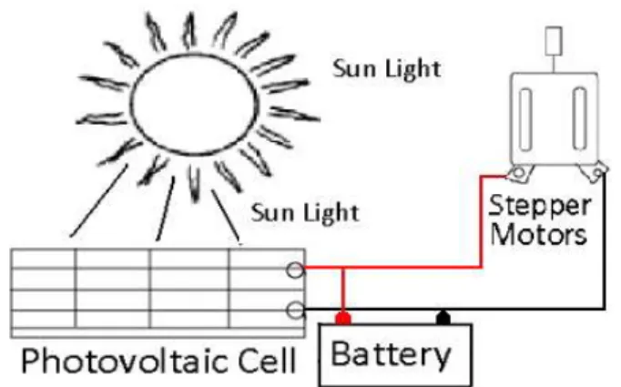
The smart solar system is a self-powered system; all components of the system depend on each others, the system does not need any supply from the external world but only sunlight. Those components interconnect with each others in order to form a closed system. The solar radiation gathered by the photovoltaic cell is transformed into electrical energy; the panel will feed the input of the charger which will charge a 12 Volt DC battery. The second functionality of the cell is to give precise voltage to the tracker, in order to reach the most efficient direction and orientation of the system which will allows maximum sunlight absorption. The battery will supply the system with a 12 Volt DC. The motors, the charger, the tracker and the sensors are supplied by the battery. The battery is charged by the photovoltaic cell through the charger
controller as shown in figure 3.3.
Figure3.3 Relations between main parts of the system
Figure 3.4 shows the block diagram of the tracking system. It explains the dependency of the tracker. As for the first running, the system has to detect sun light in a quick and accurate way, for these reason photo resistors are used. It will allows the tracking system to locate the nearest position of the light based on comparisons done in the digital processor, this will guide the system in a x-y-z plane, that means all angles and locations can be detected and reached due to the two motors (two rotational axes).The accuracy of the system is enhanced by the gear factor and ratio, the used steppers motors are of 3.5 degrees/step, with the gears added to the motors many factors were improved such as the degree/step (less degree per step which leads to better accuracy in position and angles) and high torque for the motors.
Figure3.4 Dependency of the tracker
Three photo resistors are used in the tracking system all are fixed on the upper part of the system near the photovoltaic cell in an X-O-Y manner as shown in figure 4.5. It allows a reference photo resistors the one at position O which will be compared with the photo resistors X and Y and depending on the voltage output. The tracker will compare X and O positions, the comparison will end after a very near values of outputs of those two photo resistors are reached, a loop will control the stepper motor motion and steps till a near equality of sunlight distribution will be reached. After reaching an acceptable position and values for the X-O position test, the Y-O photo resistors are tested and compared in the same manner.
Figure 3.5 Three photo resistors installed on PV
4. LDR’S (LIGHT DEPENDENT RESISTORS)
Light Dependent Resistor, Photo-resistor, or Photocell:
A Photo-resistor or Light Dependent Resistor (LDR) is a resistor whose resistance decreases with increasing
incident light intensity; in other words, it
126 All Rights Reserved © 2012 IJARCSEE
high enough frequency, photons absorbed by the
semiconductor give bound electrons enough energy to jump into the conduction band.
The resulting free electron (and its hole partner) conduct electricity, thereby lowering resistance.
A Photoelectric device can be either intrinsic or extrinsic. An intrinsic semiconductor has its own charge carriers and is not an efficient semiconductor, e.g. silicon. In intrinsic devices the only available electrons are in the valence band, and hence the photon must have enough energy to excite the electron across the entire band gap. Extrinsic devices have impurities, also called dopants, added whose ground state energy is closer to the conduction band; since the electrons do not have as far to jump, lower energy photons (i.e., longer wavelengths and lower frequencies) are sufficient to trigger the device. If a sample of silicon has some of its atoms replaced by phosphorus atoms (impurities), there will be extra electrons available for conduction. This is an example of an extrinsic semiconductor. Photo-resistors are basically photocells.
The light dependent resistor, LDR, is known by many names including the photo-resistor, photo resistor, photoconductor, photoconductive cell, or simply the photocell. It is probably the term photocell that is most widely used in data and instruction sheets for domestic equipment. The photo resistor, or light dependent resistor, LDR, finds many uses as a low cost photo sensitive element and was used for many years in photographic light meters as well as in other applications such as flame, smoke and burglar detectors, card readers and lighting controls for street lamps. Often within the literature the photo-resistor is called the photocell as a more generic term.
5. ZIGBEE
Zigbee Coordinator (ZC): The most capable device, the coordinator forms the root of the network tree and might bridge to other networks. There is exactly one Zigbee coordinator in each network since it is the device that started the network originally. It is able to store information about the network, including acting as the Trust Centre & repository for security keys.
Zigbee Router (ZR): As well as running an application function a router can act as an intermediate router, passing data from other devices.
Zigbee End Device (ZED): Contains just enough functionality to talk to the parent node (either the coordinator or a router); it cannot relay data from other devices. This relationship allows the node to be asleep a significant amount of the time thereby giving long battery life. A ZED requires the least amount of memory, and therefore can be less expensive to manufacture than a ZR or ZC.
Zigbee is a specification for a set of high level communication protocols using small, low-power digital radios based on the IEEE 802.15.4,2006 standard for wireless personal area networks (WPANs), such as wireless headphones connecting with cell phones via short-range radio. The technology defined by the Zigbee specification is intended to be simpler and less expensive than other WPANs, such as Bluetooth. Zigbee is targeted at radio frequency (RF) applications that require a low data rate, long battery life and secure networking.
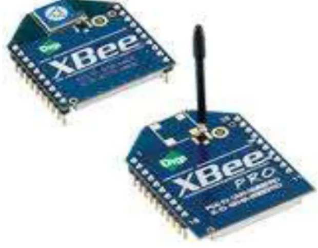
Figure 5.1 ZigBee Module
Zigbee is a low data rate, two-way standard for home automation and data networks. The standard specification for up to 254 nodes including one master, managed from a single remote control [1]. Real usage examples of Zigbee includes home automation tasks such as turning lights on, setting the home security system, or starting the VCR. With Zigbee all these tasks can be done from anywhere in the home at the touch of a button.
Zigbee protocol is optimized for very long battery life measured in months to years from inexpensive, off-the-shelf non-rechargeable batteries, and can control lighting, air conditioning and heating, smoke and fire alarms, and other
security devices. The standard supports 2.4 GHz
(worldwide),868 MHz (Europe) and 915 MHz (America) unlicensed radio bands with range up to 100 meters.
Zigbee enables broad-based deployment of wireless networks with low-cost, low-power solutions. It provides the ability to run for years on inexpensive batteries for a host of monitoring applications: Lighting controls, AMR (Automatic Meter Reading), smoke and CO detectors, wireless telemetry, HVAC control, heating control, home security, Environmental controls and shade controls, etc
5.1.1 NEED FOR ZIGBEE TECHNOLOGY
There are a multitude of standards that address mid to127 All Rights Reserved © 2012 IJARCSEE
battery lives and for large device arrays.
There are a multitude of proprietary wireless systemsmanufactured today to solve a multitude of problems that also don’t require high data rates but do require low cost and very low current drain.
These proprietary systems were designed becausethere were no standards that met their requirements. These legacy systems are creating significant interoperability problems with each other and with never technologies.
dynamic, star and mesh•
Up to 65,000 nodes on a network5.2ZIGBEE/IEEE802.15.4GENERAL CHARACTERISTICS:
Dual PHY (2.4GHz and 868/915 MHz)
Data rates of 250 kbps (@2.4 GHz), 40 kbps (@ 915
MHz), and 20 kbps (@868 MHz)
Optimized for low duty-cycle applications (<0.1%)
CSMA-CA channel access
Yields high throughput and low latency for low duty
cycle devices like sensors and controls
Low power (battery life multi-month to years)
Multiple topologies: star, peer-to-peer, mesh
Addressing space of up to18,
450,000,000,000,000,000 devices (64 bit IEEE address) 65,535 network nodes
Optional guaranteed time slot for applications
requiring low latency
Fully hand-shacked protocol for transfer reliability Range: 50m typical (5-500m based on environment)
5.2.3 Protocols: The protocols build on recent algorithmic research to automatically construct a low-speed ad-hoc network of nodes. In most large network instances, the network will be a cluster of clusters. It can also form a mesh or a single cluster. The current profiles derived from the Zigbee protocols support beacon and non-beacon enabled networks.
In non-beacon-enabled networks (those whose beacon order is 15), an unslotted CSMA/CA channel access mechanism is used. In this type of network, Zigbee Routers typically have their receivers continuously active, requiring a more robust power supply. However, this allows for heterogeneous networks in which some devices receive continuously, while others only transmit when an external stimulus is detected. The typical example of a heterogeneous network is a wireless light switch: the Zigbee node at the lamp may receive constantly, since it is connected to the mains supply, while a battery-powered light switch would remain
asleep until the switch is thrown. The switch then wakes up, sends a command to the lamp, receives an acknowledgment, and returns to sleep. In such a network the lamp node will be at least a Zigbee Router, if not the Zigbee Coordinator; the switch node is typically a Zigbee End Device.
In general, the Zigbee protocols minimize the time the radio is on so as to reduce power use. In beaconing networks, nodes only need to be active while a beacon is being transmitted. In non-beacon-enabled networks, power consumption is decidedly asymmetrical: some devices are always active, while others spend most of their time sleeping.
Zigbee devices are required to conform to the IEEE 802.15.4-2003 Low-Rate Wireless Personal Area Network (WPAN) standard. The standard specifies the lower protocol layers—the physical layer, and the medium access control portion of the data link layer). This standard specifies operation in the unlicensed 2.4 GHz, 915 MHz and 868 MHz ISM bands. In the 2.4 GHz band there are 16 Zigbee channels, with each channel requiring 5 MHz of bandwidth. The basic
channel access mode is "carrier sense, multiple
access/collision avoidance" (CSMA/CA). That is, the nodes talk in the same way that people converse; they briefly check to see that no one is talking before they start. There are three notable exceptions to the use of CSMA. Beacons are sent on a fixed timing schedule, and do not use CSMA. Message acknowledgments also do not use CSMA.
Software and hardware
The software is designed to be easy to develop on small, inexpensive microprocessors. The radio design used by Zigbee has been carefully optimized for low cost in large scale production. It has few analog stages and uses digital circuits wherever possible.
Even though the radios themselves are inexpensive, the Zigbee Qualification Process involves a full validation of the requirements of the physical layer. This amount of concern about the Physical Layer has multiple benefits, since all radios derived from that semiconductor mask set would enjoy the same RF characteristics. On the other hand, an uncertified physical layer that malfunctions could cripple the battery lifespan of other devices on a Zigbee network. Zigbee radios have very tight engineering constraints: they are both power and bandwidth constrained. Thus, radios are tested to the ISO 17025 standard with guidance given by Clause 6 of the 802.15.4-2006 Standard. Most vendors plan to integrate the radio and microcontroller onto a single chip.
4.2.4 Advantages:
Low cost allows the technology to be widely
deployed in wireless control and monitoring applications.
128 All Rights Reserved © 2012 IJARCSEE
Mesh networking provides high reliability and larger
range.
5. EXPERIMENTAL RESULTS :
129 All Rights Reserved © 2012 IJARCSEE
6. CONCLUSION:
In this paper a universal multi-function solar tracker system is reported. The proposed system was implemented in reduced complexity architecture such as a microcontroller. The control system which is the brain of the proposed system is used to turn a small PV panel in three directions to determine the maximum output current. Three photo resistors are used every 45 minutes to redirect the PV panel to know the nearest value of the maximum sun radiation.
In order to collect the greatest amount of energy from the sun, solar panels must be moved according to the movement of sun. For this purpose, a new solar tracking technique based on microcontroller was implemented and tested in this study. The tracking system presented has the following advantages: In sunny countries, solar power can be used where there is no easy way to get electricity to a remote place. Handy for low-power uses such as, solar powered garden lights and battery chargers. The tracker provides also PC based system monitoring facility. Since the tracking system is controlled completely by Microcontroller, the PC, used for monitoring the panel only. In this paper, the sun’s light is tracked (east – central- west). But still the power generation by tracking the sunlight in (north - south) is improved.
8. FUTURE SCOPE
The extension of this project would be to directly power the microcontroller and other circuits from the solar panel instead of from a power supply. Or to incorporate a power supply into the system that draws energy from the solar panel or an energy storage element that is in turn charged by the solar panel. This extension would allow the system to be deployed to remote locations.
The goals of this project were purposely kept within what was believed to be attainable within the allotted timeline. As such, many improvements can be made upon this initial design. That being said, it is felt that this design represents a functioning miniature scale model which could be replicated to a much larger scale. The following recommendations are provided as ideas for future expansion of this project:
Increase the sensitivity and accuracy of tracking by using a different light sensor.
Phototransistor with an amplification circuit would provide improved resolution and better tracking accuracy/precision.
Utilize a dual-axis design versus a single-axis to increase tracking accuracy.
REFERENCES:
1 A. Zahedi, “Energy, People, Environment, Development of an integrated renewable energy and energy storage system, an uninterruptible power supply for people and for better environment,” The International Conference on Systems, Man, and Cybernetics, 1994. 'Humans, Information and Technology', Vol. 3 pp. 2692-2695, 1994.
2 R. Singh, and Y.R. Sood, “Transmission tariff for restructured Indian power sector with special consideration to promotion of renewable energy sources”, The IEEE Conference TENCON-2009, pp. 1-7, 2009.
3 J. Arai, K. Iba, T. Funabashi; Y. Nakanishi, K. Koyanagi, and R.Yokoyama, “Power electronics and its applications to renewable energyin Japan, ” The IEEE Circuits and Systems Magazine, Vol. 8, No. 3, pp.52-66, 2008.
4 S. Takemaro and Shibata Yukio, “Theoretical Concentration of SolarRadiation by Central Receiver Systems,” The International Journal ofSolar Energy, 261-270, 1983.
5 S. Armstrong and W.G Hurley “Investigating the Effectiveness of Maximum Power Point Tracking for a Solar System”, The IEEEConference on Power Electronics Specialists, pp.204-209, 2005.
130 All Rights Reserved © 2012 IJARCSEE
Authors Biography:
T.NAGALAXMI working as an Assistant professor in ECE department at Vidya Jyothi institute of technology,hyderabaad from 2008 to till date. And completed M.TECH(Embedded systems) ,affiliated college by JNTUH. She is having six years of teaching experience.
Her areas of research interests are embedded systems, VLSI,
embedded and real time systems digital signal processing and architectures ,Microprocessor & Microcontroller ,digitaldatacominication.
VARADALA SRIDHAR is from HYDERABAD, ANDHRAPRADESH.Completed M.TECH in ECE with
specialization (WIRELESS AND MOBILE
COMMUNICATION SYSTEMS) from vardhaman college
of engineering affiliated by JNTUH in 2011.he has
completed M.Sc (IT)from Nagarjuna University, guntur,
AndhraPradesh.and B.TECH in ECE from vidya jyothi
institute of technology affiliated by JNTUH in 2007.
Currently he is working as an Assistant professor in ECE department at Vidya Jyothi Institute of Technology, Hyderabad from 2010. he is having more than 3 years experience as an assistant professor. His areas of research
interests include Wireless and Mobile
communicationsystems,Digitalsignalprocessing,Imageproc essing,Telecommunications,communicationsystems, Signal processing,Embedded systems. He has published international journals papers.He is Lifetime Membership of ISTE, IETE.
M.REJENDRA PRASAD obtained his B.E and M.E Electronics and communication engineering and digital systems from OSMANIA UNIVERSITY, hyderabad.HE has 11 years of experience in embedded and telecom research and development. He is currently working as an associate
professor, ECE, DEPARTMENT, VJIT, HYD. He has