Current Control of Three Phase Grid
–
Connected PV
Inverter Using Fuzzy Logic Controller
P Sai Manikanta1 , K Venkata Ramana2
M.Tech Scholar, Department of EEE, PCET, Anathavaram, India.1 Asso. Professor, Department of EEE, PCET, Anathavaram ,India.2
Abstract- Distributed Generation (DG) is
now widely employed in many electricity generation networks. It is mostly based on energy storage and renewable energy sources such as wind turbines (WT), photovoltaic cells (PV) and fuel cells to minimize pollution and greenhouse gas emissions. For large scale installations, a three phase power electronic inverter utilized to interface the source of renewable energy to the utility grid. The inverter and the associated control system are at the core of the energy conversion process and their operation is essential to inject high power quality, low harmonic distortion, current to the grid. For this reason international harmonic and power quality recommendations, such as IEEE Standard 519 and 1547, are often in place to limit the harmonic currents injected into the grid. Typically, 5% current total harmonic distortion (THD) limit is imposed. A Fuzzy controller is also implemented in this project in order to reduce the total harmonic distortion. In addition, the fuzzy and adaptive PR controller offers superior output power regulation, and improved power quality performance. Results are analyzed through MATLAB/SIMULINK environment
I. INTRODUCTION
Distributed Generation (DG) is now widely employed in many electricity generation networks. It is mostly based on energy storage and renewable energy sources such as wind turbines (WT), photovoltaic cells (PV) and fuel cells to minimize
pollution and greenhouse gas emissions [1]. For large scale installations, a three phase power electronic inverter utilized to interface the source of renewable energy to the utility grid. The inverter and the associated control system are at the core of the energy conversion process and their operation is essential to inject high power quality, low harmonic distortion, current to the grid [2]. For this reason international harmonic and power quality recommendations, such as IEEE Standard 519 and 1547, are often in place to limit the harmonic currents injected into the grid [3]. Typically, 5% current total harmonic distortion (THD) limit is imposed. Numerous inverter current control techniques have been proposed to achieve improved power quality waveforms.
Furthermore, the Park transformation is not necessary, and there is less cross coupling of the control axis, hence de-coupling strategies are not required [8]. As a result, in grid connected applications, significant reduction in the harmonic content of the controlled current is possible. Additional elimination of the harmonic content can be achieved by implementing Harmonic Compensation (HC) terms in parallel with the main control effort [9]. However, a sudden drop in the voltage could further increase the error between the reference signal and the controlled signal causing considerable deviation from its nominal value. The performance of the conventional PR controller will not keep up with the increase in the error which weakens the controller performance. To overcome this issue, this project presents an improvement in current control using a novel adaptive PR controller. It demonstrates and compares the performance of the adaptive PR controller during normal and abnormal grid voltage conditions. The proposed control technique is capable of providing low total harmonic distortion (THD) of the injected current even during the occurrence of abnormal grid conditions. The proposed method also achieves lower overshoot, settling time as well as steady-state error.
In addition, this project presents a simple method to decompose the voltage and the current into their positive and negative sequence components based on adaptive delayed filter with one-quarter period delay. The performance of the adaptive control strategy is verified by simulation. A three phase grid connected inverter is modeled and controlled using adaptive PR controller strategy based on the stationary reference frame point of view with space vector modulation technique (SVM). As a result, a phase locked loop (PLL) is used here in this control to detect the transformation angle and enhance the synchronization of the inverter output current with the grid voltages achieved. Two adaptive PR current controllers together with harmonic compensators are applied in the current controller. The control scheme does not have any coupling between active and reactive components, and the results show that it provides excellent dynamic response.
in the number of grid connected three phase inverter systems being connected to the distribution network. As a result, the need for high quality, low harmonic distortion, current injection into the grid is essential. To achieve this, careful consideration of the inverter controller is necessary. Many control methods are based on the traditional proportional-integral controller (PI), or the more recently adopted Proportional Resonant controller (PR). This project presents a new technique of minimizing the error of the current control in a three phase grid connected inverter using a readily implementable Adaptive Proportional Resonance controller. A Fuzzy controller is also implemented in this project in order to reduce the total harmonic distortion. In addition, the fuzzy and adaptive PR controller offers superior output power regulation, and improved power quality performance.
II. LCL Filter Design
Fig.1 shows a three-phase grid connected inverter with a third order LCL filter. The LCL filters improve the power quality of the current injected to the grid compared to lower order L and LC filters
Fig.1 Three phase inverter connected with LCL filter
Fig.2 Equivalent circuit of single phase LCL filter
Since SVM is used in this system, the LCL filter is
designed in the stationary reference frame (αβ) using
space vectors to make it easier and more convenient.
By applying Kirchhoff’s voltage and current laws, the
following equations can be used to represent the voltages and currents within the circuit of Fig.2 [11].Inverter vector equations, dc voltage, capacitor voltage and LCL filter current equations are given by project [1].
III .Control Scheme
In this work, the applied control system is a cascaded system with an inner current control loop controlled by an outer voltage control loop. The block diagram of the adaptive PR current control scheme is presented in Fig.3. The system consist of PV array with maximum power point comprised of dc-dc converter following by three phase dc-ac inverter [3, 4]. The voltage control loop comprises of two PI regulators; one for the dc link voltage control and the other for the grid voltage control. The measured dc voltage is compared with the reference dc voltage
Fig.3: Adaptive PR controller in stationary Reference
control
Fig.4: Controller diagram of PR Controller
The measured voltage is converted to the synchronous reference frame, and the q-component, vq is compared with the reference vq * which is equal to zero and controlled by a PI controller. The nominal grid
frequency ω is added to the output of the PI controller,
and the sum is integrated to obtain the grid
voltage angle θ.
IV. BRIEF OF THE INSTANTANEOUS POWER
THEORY
As the name suggested, the prompt power hypothesis depends on a meaning of immediate genuine and receptive powers in time space. It is exceptionally valuable in the enduring state as well as in the transient state investigation for both three-stage frameworks with or without an impartial conductor. To represent the hypothesis, let think about an arrangement of immediate three stage amount, for instance a v ,b v and c v . It begins with changing an arrangement of three-stage factors in the abc into αβ 0
facilitates. This change is purported as the Clark change as portrayed takes after.
…… ……… (2)
In three-phase, three-wire systems, there is no zero sequence components. If 0 v and 0 i are both neglected, instantaneous voltage, v, and current phasors, i, can be defined from their corresponding
instantaneous α and β components as follows
v=vα+ jvb……….. (3)
i=iα+ jiβ………. (4)
From (3) and (4), instantaneous complex powers, s, can be defined as the product of the instantaneous voltage phasor and the complex conjugate of the instantaneous current phasor given in (5).
s=vi∗=(vα+ jvβ)(iα–jiβ)=p+jq……… (5)
Where,
P=vαiα+ vβiβp is the instantaneous active power
q=vβiα−vαiβ is the instantaneous reactive power
The instantaneous complex power is useful. It can be applied for transient or steady-state analysis. The following equation is a compact form for the instantaneous real and reactive power definition and its inversion.
……… (6)
……… …… (7)
………. (8)
……….. (9)
V.FUZZY CONTROLLER
INTRODUCTION:
The word Fuzzy means vagueness. Fuzziness occurs when the boundary of piece of information is not clear-cut. In 1965 Lotfi A. Zahed propounded the
huge potential for powerful tackling of the vulnerability in the issue. Fuzzy set hypothesis is a phenomenal scientific apparatus to deal with the vulnerability emerging because of ambiguity. Understanding human discourse and perceiving written by hand characters are some basic cases where fluffiness shows.
Fuzzy set hypothesis is an expansion of established set hypothesis where components have fluctuating degrees of enrollment. Fuzzy rationale utilizes the entire interim in the vicinity of 0 and 1 to depict human thinking. In FLC the information factors are mapped by sets of participation capacities and these are called as "Fuzzy SETS".
Fuzzy set contains from a participation work which could be characterizes by parameters. The incentive in the vicinity of 0 and 1 uncovers a level of enrollment to the fuzzy set. The way toward changing over the fresh contribution to a fuzzy esteem is called as "fuzzificaton." The yield of the Fuzzier module is interfaced with the standards. The essential activity of FLC is built from fuzzy control rules using the estimations of fuzzy sets as a rule for the blunder and the difference in mistake and control activity. Essential fuzzy module is appeared in fig.5
The outcomes are joined to give a fresh yield controlling the yield variable and this procedure is called as "DEFUZZIFICATION."
VI.SIMULINK DESIGN AND RESULTS
FIG 6: Simulink Block Diagram.
FIG 7:Boost Converter Control Circuit Diagram.
FIG 8:Fuzzy Logic Controller Diagram.
Simulation Results:
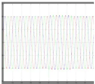
Fig9:Three phase voltage waveform
Fig. 9 and 10 shows the simulation results of the three
phase voltage and current. Fig.9 shows the three phase
voltage waveform.
Fig10:Three phase voltage waveform
It can be seen that the voltage drops when a voltage sags happens in the system at 0.1 sec until 0.15 sec. Fig.10 shows three phase current waveform. It is clear that the current
has increased when the sudden voltage occur at 0.1 sec in order to balance the active power transfer from the PV source. Fig.13 shows the stationary reference frame (alpha) current
variation in the current waveform.
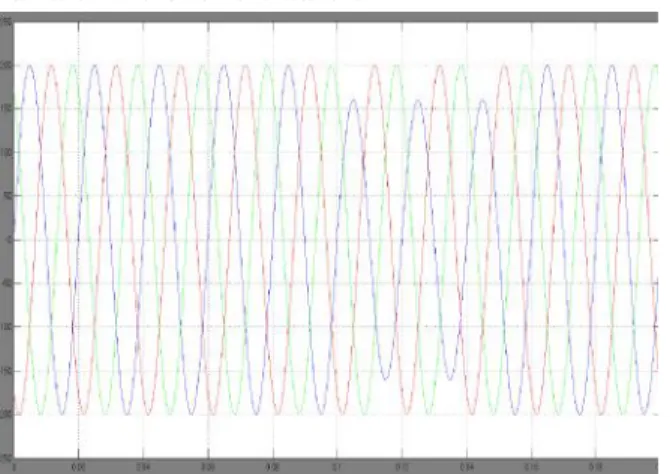
Fig11:Simulation Waveform for unbalanced grid
condition : three phase voltage waveform
Fig12:Simulation Waveform for unbalanced grid
condition : three phase current waveform
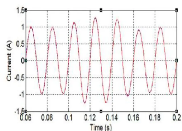
Fig.13 and Fig.14 show the stationary reference frame alpha and beta current waveform respectively. The measured current following the reference current which they
point out that the fuzzy controller works effectively when there is change in the grid conditions. However, in the case of unbalanced voltage sag the fuzzy controller achieves better dynamic response. Fig.11 and 12 shows the three phase voltage and current waveform respectively; note the reduction in the overshoot characteristics and the recovery time to achieve steady state. It is clear that the adaptive
current. It can be shown that this is due to the adaptive and fuzzy controllers improved ability to regulate the positive and negative sequence components.
FIG 13: Simulation Waveforms for Conventional PR
FIG 14: Simulation Waveforms for Adaptive PR
controller i-alpha and i-beta
FIG15: Total Harmonic Distortion
CONCLUSION
This thesis has considered the impact of an adaptive PR current controller and fuzzy controller scheme of a three phase grid connected inverter. In particular, this work has shown the performance of the adaptive PR controller compared with the conventional PR controller which is popular in grid connected inverters. Simulation studies confirm that the adaptive PR controller demonstrates better performance under normal and abnormal operating conditions. There is no steady state error output, and the harmonic content of the current waveform is very low. A Fuzzy controller is also implemented in this
project in order to reduce the total harmonic distortion. In addition, the fuzzy and adaptive PR controller offers superior output power regulation, and improved power quality performance. Overall, it can be concluded that the adaptive PR and fuzzy controllers are better suited in the event of grid faults, or operation in weak grid environments, compared to fix gain controllers.
REFERENCES:
[1] A. Althobaiti, M. Armstrong, and M. A. Elgendy
“Current Control of Three-phase Grid-connected PV
Inverters using Adaptive PR Controller”IEEE project-2016
[2] M. Castilla, J. Miret, J. Matas, L. G. de Vicua, and J. M. Guerrero, "Linear Current Control Scheme With Series Resonant Harmonic Compensator for Single-Phase Grid-Connected Photovoltaic Inverters,"
Industrial Electronics, IEEE Transactions on, vol. 55,
pp. 2724-2733, 2008.
[3] A. Nicastri and A. Nagliero, "Comparison and evaluation of the PLL techniques for the design of the grid-connected inverter systems," in Industrial Electronics (ISIE), 2010 IEEE International Symposium on, 2010, pp. 3865-3870.
[4] R. Teodorescu, F. Blaabjerg, M. Liserre, and P. C. Loh, "Proportional-resonant controllers and filters for grid-connected voltage-source converters," Electric
Power Applications, IEE Proceedings, vol. 153, pp.
750-762, 2006.
[5] M. Liserre, R. Teodorescu, and F. Blaabjerg, "Multiple harmonics control for three-phase grid converter systems with the use of PIRES current controller in a rotating frame," Power Electronics,
IEEE Transactions on, vol. 21, pp. 836-841, 2006.
[6] M. Liserre, F. Blaabjerg, and S. Hansen, "Design and control of an LCL-filter-based three-phase active rectifier," Industry Applications, IEEE Transactions
on, vol. 41, pp. 1281-1291, 2005.
1250, 2011.
[8] B. Chenlei, R. Xinbo, W. Xuehua, L. Weiwei, P. Donghua, and W. Kailei, "Step-by-Step Controller Design for LCL-Type Grid- Connected Inverter with Capacitor–Current-Feedback Active-Damping," Power Electronics, IEEE Transactions on, vol. 29, pp. 1239-1253, 2014.
[9] "IEEE Standard for Interconnecting Distributed Resources With Electric Power Systems," IEEE Std