®
Serial Download Cable
February 2002, ver. 4.3 Data Sheet
De
vel
o
p
m
en
t
13
To
o
ls
Features
■ Allows PC and UNIX workstation users to perform the following functions:– Program MAX® 9000, MAX 7000S, MAX 7000A, and
MAX 3000A devices in-system via a standard RS-232 serial port – Configure FLEX®10K, FLEX 8000, and FLEX 6000 devices
in-circuit via a standard RS-232 serial port
■ Downloads data from:
– MAX+PLUS® II development software on PCs and UNIX workstations
– A system prompt on PCs and UNIX workstations
■ Provides two data download modes: passive serial (PS) and JTAG
■ Programs/configures a single device or multiple devices in a chain
■ Supports data transfer rates from 9,600 to 230,400 baud
Functional
Description
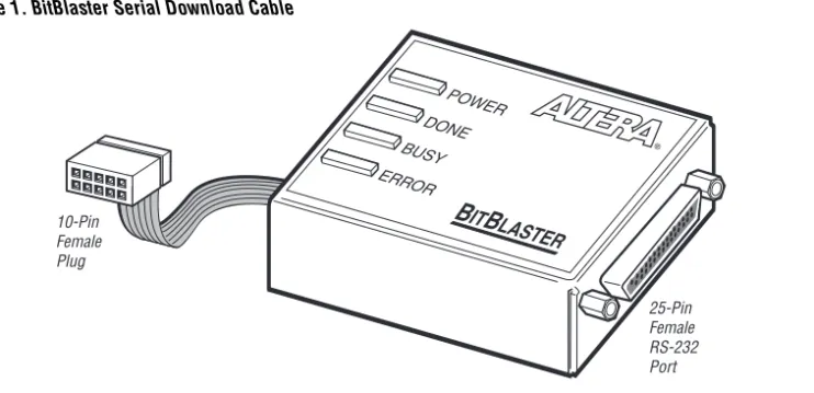
The BitBlaster™ serial download cable (ordering code: PL-BITBLASTER) is a hardware interface to a standard RS-232 port (called a “COM port” on PCs and either a “ttya port” or “ttyb port” on UNIX workstations). This cable channels configuration data to FLEX 10K, FLEX 8000, and
FLEX 6000 devices, as well as programming data to MAX 9000 (including MAX 9000A), MAX 7000S, MAX 7000A, and MAX 3000A devices. Because design changes are downloaded directly to the device, prototyping is easy, and multiple design iterations can be accomplished in quick succession. See Figure 1.
Figure 1. BitBlaster Serial Download Cable
Data Download Modes
The BitBlaster cable provides two data download modes:
■ Passive serial (PS) mode—Used for configuring FLEX 10K, FLEX 8000, and FLEX 6000 devices
■ JTAG mode—Industry-standard JTAG boundary-scan test (BST) circuitry (compliant with IEEE Std. 1149.1-1990) implemented for programming or configuring FLEX 10K, MAX 9000, MAX 7000S, MAX 7000A, and MAX 3000A devices.
BitBlaster Connections
Data is downloaded from the computer’s RS-232 port through the BitBlaster cable to the circuit board via the connections described in this section.
1 To configure/program 3.3-V devices (e.g., FLEX 10KA, FLEX 10KB, FLEX 10KE, MAX 7000A, and MAX 3000A devices) using the BitBlaster cable, connect the cable’s VCC pin to a 5.0-V power supply and the device to a 3.3-V power supply. 3.3-V Altera devices have 5.0-V tolerant inputs, so the BitBlaster cable’s 5.0-V output will not harm these 3.0-V devices. The pull-up resistors should be connected to the 5.0-V power supply.
POWER DONE BUSY ERROR
B
IT
B
LASTER
25-Pin Female RS-232 Port 10-Pin
Female Plug
D
e
ve
lopm
e
n
t
13
To
ol
s
BitBlaster Female Port & Plug Connections
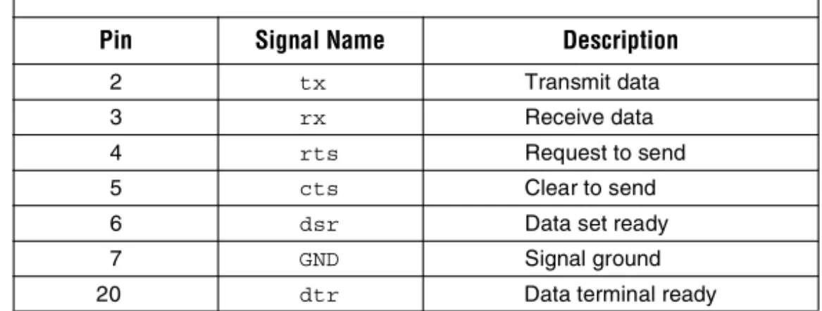
The 25-pin female port connects to an RS-232 port with a standard serial cable. See Table 1.
The 10-pin female plug connects to a 10-pin male header on the circuit board containing the target device(s). Figure 2 shows the dimensions for the 10-pin female plug.
Table 1. BitBlaster 25-Pin Serial Port Pin-Outs
Pin Signal Name Description
2 tx Transmit data
3 rx Receive data
4 rts Request to send
5 cts Clear to send
6 dsr Data set ready
7 GND Signal ground
Figure 2. BitBlaster 10-Pin Female Plug Dimensions
Dimensions are shown in inches. The spacing between pin centers is 0.1 inch.
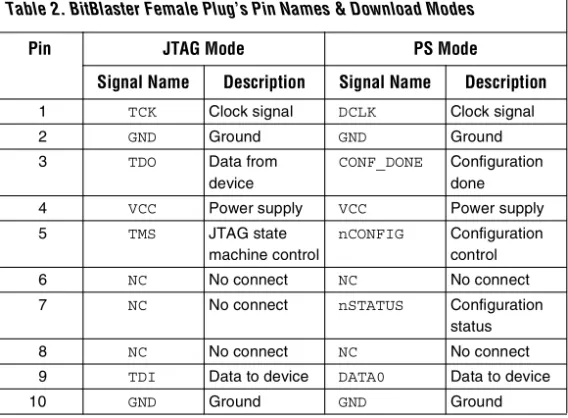
Table 2 identifies the 10-pin female plug’s pin names for the corresponding download mode.
0.250 Typ.
0.700 Typ. 0.425 Typ.
0.100 Sq. 1
2 3
4 5
6 7
8 9
10
0.025 Sq.
Color Strip
Table 2. BitBlaster Female Plug’s Pin Names & Download Modes
Pin JTAG Mode PS Mode
Signal Name Description Signal Name Description
1 TCK Clock signal DCLK Clock signal
2 GND Ground GND Ground
3 TDO Data from
device
CONF_DONE Configuration done
4 VCC Power supply VCC Power supply
5 TMS JTAG state
machine control
nCONFIG Configuration control
6 NC No connect NC No connect
7 NC No connect nSTATUS Configuration
status
8 NC No connect NC No connect
9 TDI Data to device DATA0 Data to device
D
e
ve
lopm
e
n
t
13
To
ol
s
Circuit Board Header Connection
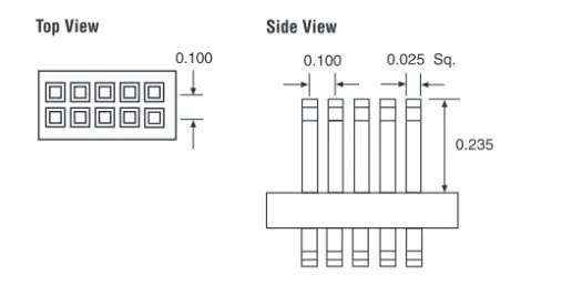
The BitBlaster 10-pin female plug connects to a 10-pin male header on the circuit board. The 10-pin male header has two rows of five pins connecting the circuit board to the device’s programming or configuration pins. The BitBlaster cable receives power and downloads data via the male header. Figure 3 shows the dimensions of a typical 10-pin male header.
Figure 3. 10-Pin Male Header Dimensions
Dimensions are shown in inches.
1 The circuit board must supply VCC and ground to the BitBlaster cable.
BitBlaster Status Lights
The BitBlaster status lights indicate the state of the device configuration or programming. See Table 3.
0.025 Sq.
0.235 0.100
Side View 0.100
Top View
Table 3. BitBlaster Status Lights
Status Light Description
POWER Indicates a connection to the target system’s power supply. DONE Indicates that device configuration or programming is complete. BUSY Indicates that device configuration or programming is in progress. ERROR Indicates error detection during configuration or programming.
Data Transfer Rate
Control &
Operating
Conditions
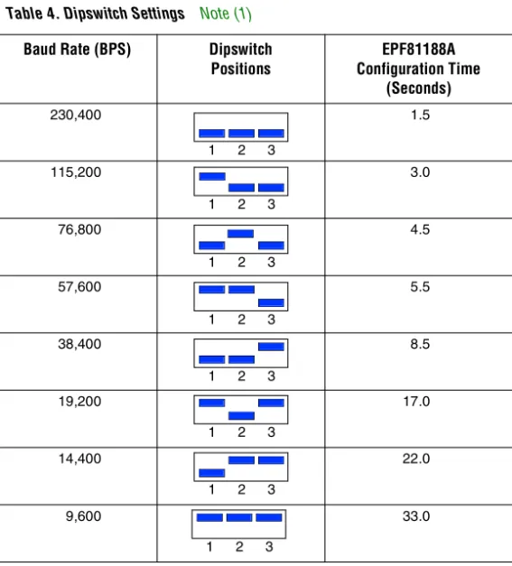
Three dipswitches on the side panel of the BitBlaster cable control the baud rate of the serial data. Table 4 shows the on/off dipswitch settings, which can be used to specify transfer rates ranging from 9,600 to 230,400 baud. The configuration time for an EPF81188A device, which uses 193,000 bits of configuration data, is also provided for reference.
Note:
(1) The supported baud rates vary depending on the computer system. Refer to
the computer system’s serial port hardware documentation to verify the available baud rates.
f
Search for “Hardware Setup command” in MAX+PLUS II Help for more information.Table 4. Dipswitch Settings Note (1)
Baud Rate (BPS) Dipswitch
Positions
EPF81188A Configuration Time
(Seconds)
230,400 1.5
115,200 3.0
76,800 4.5
57,600 5.5
38,400 8.5
19,200 17.0
14,400 22.0
9,600 33.0
1 2 3
1 2 3
1 2 3
1 2 3
1 2 3
1 2 3
1 2 3
D
e
ve
lopm
e
n
t
13
To
ol
s
Operating
Conditions
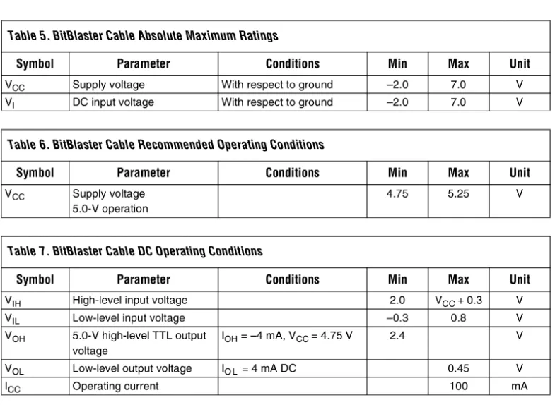
The Tables 5 through 7 summarize the absolute maximum ratings, recommended operating conditions, and DC operating conditions for the BitBlaster cable.
Table 5. BitBlaster Cable Absolute Maximum Ratings
Symbol Parameter Conditions Min Max Unit
VCC Supply voltage With respect to ground –2.0 7.0 V
VI DC input voltage With respect to ground –2.0 7.0 V
Table 6. BitBlaster Cable Recommended Operating Conditions
Symbol Parameter Conditions Min Max Unit
VCC Supply voltage 5.0-V operation
4.75 5.25 V
Table 7. BitBlaster Cable DC Operating Conditions
Symbol Parameter Conditions Min Max Unit
VIH High-level input voltage 2.0 VCC +0.3 V
VIL Low-level input voltage –0.3 0.8 V
VOH 5.0-V high-level TTL output voltage
IOH = –4 mA, VCC = 4.75 V 2.4 V
VOL Low-level output voltage IO L = 4 mA DC 0.45 V
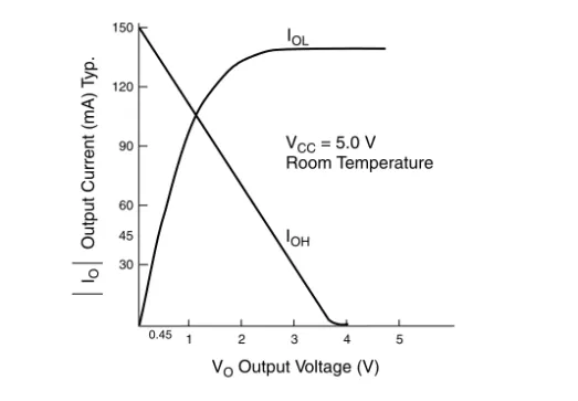
Figure 4 shows the typical 5.0-V output drive characteristics of the BitBlaster cable.
Figure 4. BitBlaster Output Drive Characteristics
Software
Instructions
The MAX+PLUS II Programmer downloads configuration or programming data. For FLEX 10K, FLEX 8000, and FLEX 6000 devices, configuration data can also be downloaded by copying the SBF to the RS-232 port from the system prompt.
Downloading Configuration or Programming Data from the
MAX+PLUS II Programmer
To configure or program one or more devices with the BitBlaster cable and the MAX+PLUS II Programmer, follow these steps: 1. Compile a project. The MAX+PLUS II Compiler automatically
generates an SOF for FLEX 10K, FLEX 8000, and FLEX 6000 device configuration, or a POF for MAX 9000, MAX 7000S, MAX 7000A, or MAX 3000A device programming.
2. Attach the BitBlaster cable to an RS-232 port on a PC or UNIX workstation and plug the 10-pin female header into the system containing the target device. Ensure that the POWER status light is on. The board must supply power to the BitBlaster cable.
VO Output Voltage (V)
1 2 3 4 5
30 60 90 150
120
0.45
VCC = 5.0 V
IOL
IOH
Room Temperature
IO
Output Current (mA)
T
yp.
D
e
ve
lopm
e
n
t
13
To
ol
s
3. If necessary, change the BitBlaster cable’s baud rate using the dipswitches on its side panel. Dipswitch settings are listed in Table 4 on page 6.
4. Open the MAX+PLUS II Programmer. Choose the Hardware Setup command (Options menu) to specify the BitBlaster cable and the appropriate RS-232 port. See “Changing the Hardware Setup” in MAX+PLUS II Help for more information.
1 When you first open the Programmer, the MAX+PLUS II software automatically loads the programming file for the current project (either a POF or SOF), or the first
programming file for a multi-device project. To specify another programming file, choose Select Programming File (File menu) and specify the correct file type. For a FLEX 10K, FLEX 8000, or FLEX 6000 device, select an SOF; for a MAX 9000, MAX 7000S, MAX 7000A, or MAX 3000A device, select a POF.
5. For JTAG or FLEX-chain programming or configuration, perform the following:
v To program or configure devices in a JTAG chain (multi- or single-device chain), turn on Multi-Device JTAG-Chain (JTAG menu) and choose Multi-Device JTAG Chain Setup to set up the multi-device JTAG chain. See “Setting up Multi-Device JTAG Chains” in MAX+PLUS II Help for more information.
1 If the JTAG chain includes either FLEX or MAX devices exclusively, set up and create just one JTAG Chain File (.jcf). If the JTAG chain includes a mixture of FLEX and MAX devices, set up and create two separate JCFs.
v To configure multiple devices in a FLEX chain, turn on Multi-Device FLEX Chain (FLEX menu) and choose Multi-Device FLEX Chain Setup to setup the multi-device FLEX chain. See “Setting Up Multi-Device FLEX Chains” in MAX+PLUS II Help for more information.
6. Choose the Program or Configure button to program or configure the device(s). The BUSY status light on the BitBlaster cable turns on.
The BitBlaster cable downloads the data from the SOFs or POFs into the device(s). When configuration or programming is complete, the BUSY status light turns off, and the DONE status light turns on. After the DONE status light turns on, the BitBlaster can be disconnected.
Downloading Configuration Data from a System Prompt
(FLEX Devices Only)
To configure one or more FLEX 10K, FLEX 8000, or FLEX 6000 devices with the BitBlaster cable from a system prompt, follow these steps:
1. Compile the project(s) with the MAX+PLUS II Compiler. The Compiler automatically generates an SOF for device
configuration.
2. Open the MAX+PLUS II Programmer or Compiler and choose the Convert SRAM Object Files command (File menu). 3. Specify the SOF name by selecting it in the Files box or by
typing its name in the File Name box. Choose Add to add the file to the Selected Files box.
4. Specify the serial bitstream file format by selecting .sbf (Sequential) in the File Format drop-down list box. Choose OK. 5. Attach the BitBlaster cable to an RS-232 port on your PC or
UNIX workstation, and plug the 10-pin female header into the prototype system that contains the target FLEX 10K, FLEX 8000, or FLEX 6000 device(s). Ensure that the POWER status light is on. The board must supply power to the BitBlaster cable. 6. If necessary, change the baud rate of the BitBlaster cable using
the dipswitches on its side panel. Dipswitch settings are listed in Table 4 on page 6.
7. Specify the baud rate of the target RS-232 (serial) port.
v On a PC, type the following command at the system prompt:
D
e
ve
lopm
e
n
t
13
To
ol
s
1 Older versions of DOS may not support rates greater than 9,600 baud. Altera provides a
slikmode.exe utility that sets higher rates for these older operating systems. The
slikmode.exe utility is available from the
/pub/misc directory of the Altera FTP site (ftp.altera.com) as a self-extracting executable, bitmode.exe. To use the
slikmode.exe utility, type the following command at the system prompt:
slikmode/b<baud rate>/c<serial port
number>
For instructions on using the slikmode.exe
utility, type slikmode at the system prompt.
v Because commands on UNIX workstations differ depending on the operating system, the following command is provided only as an example. On a UNIX workstation, type the following command from the system prompt:
stty <baud rate> /dev/<serial port id>
Check the workstation specifications to determine the maximum baud rate allowed by the hardware.
8. Configure the FLEX 10K, FLEX 8000, or FLEX 6000 device by copying the SBF to the serial port to which the BitBlaster cable is attached.
v On a PC, type the following command from the system prompt:
copy <filename>.sbf com<serial port number>:
v Because commands on UNIX workstations differ depending on the operating system, the following command is provided only as an example. On a UNIX workstation, type the following command from the system prompt:
Conclusion
Downloading configuration and programming data directly to the device via the BitBlaster cable allows designers to verify multiple design iterations in quick succession, thereby speeding the design cycle.References
For more information on configuration and in-system programmablility (ISP), see the following sources:■ Application Note 116 (Configuring APEX 20K, FLEX 10K & FLEX 6000 Devices)
■ Application Note 33 (Configuring FLEX 8000 Devices)
■ Application Note 38 (Configuring Multiple FLEX 8000 Devices)
■ Application Note 39 (IEEE 1149.1 (JTAG) Boundary-Scan Testing in Altera Devices)
■ Application Note 95 (In-System Programmability in MAX Devices)
■ Search for “Configuring a Single Device with the BitBlaster, ByteBlaster, or FLEX Download Cable,” “Setting Up Multi-Device JTAG Chains,” ”Configuring Multiple Multi-Devices in a JTAG Chain with the BitBlaster or ByteBlaster,” and “Programming a Single Device with BitBlaster or ByteBlaster” in MAX+PLUS II Help.
Revision History
The information contained in the BitBlaster Serial Download Cable Data Sheet version 4.3 supersedes information published in previous versions.Version 4.3 Changes
The BitBlaster Serial Download Cable Data Sheet version 4.3 contains the following changes: updated procedures in “Downloading Configuration Data from a System Prompt (FLEX Devices Only)” on page 10.
D
e
ve
lopm
e
n
t
13
To
ol
s
Version 4.02 Changes
The BitBlaster Serial Download Cable Data Sheet version 4.02 contains the following changes:
■ Information on MAX 3000A devices was added throughout the document.
■ The “Passive Serial Mode” section was removed. This information is found in Application Note 116 (Configuring APEX 20K, FLEX 10K & FLEX 6000 Devices).
■ The “JTAG Mode” section was removed. This information is found in Application Note 39 (IEEE 1149.1 (JTAG) Boundary-Scan Testing in Altera Devices) and Application Note 95 (In-System Programmability in MAX Devices).
■ The “References” section was added, which provides sources for additional information on the BitBlaster download cable.
■ Minor textual, illustration, and style changes were made to the data sheet.
Version 4.01 Changes
The BitBlaster Serial Download Cable Data Sheet version 4.01 contains the following changes:
■ References to MAX 9000A devices were added as needed.
■ References to FLEX 10KB and FLEX 10KE devices were added to the configuring/programming 3.3-V devices paragraph in the “BitBlaster Connections” section.
■ Minor textual, illustration, and style changes were made to the data sheet.
Copyright © 2002 Altera Corporation. All rights reserved. Altera, The Programmable Solutions Company, the stylized Altera logo, specific device designations, and all other words and logos that are identified as trademarks and/or service marks are, unless noted otherwise, the trademarks and service marks of Altera Corporation in the U.S. and other countries. All other product or service names are the property of their respective holders. Altera products are protected under numerous U.S. and foreign patents and pending applications, mask work rights, and copyrights. Altera warrants performance of its semiconductor products to current specifications in accordance with Altera's standard warranty, but reserves the
right to make changes to any products and services at any time without notice. Altera assumes no responsibility or liability arising out of the application or use of any information, product, or service described herein except as expressly agreed to in writing by Altera Corporation. Altera customers are advised to obtain the latest version of device
101 Innovation Drive San Jose, CA 95134 (408) 544-7000 http://www.altera.com
Applications Hotline: