Data Integrator Guide
Operations Center 5.0
Legal Notices
THIS DOCUMENT AND THE SOFTWARE DESCRIBED IN THIS DOCUMENT ARE FURNISHED UNDER AND ARE SUBJECT TO THE TERMS OF A LICENSE AGREEMENT OR A NON‐DISCLOSURE AGREEMENT. EXCEPT AS EXPRESSLY SET FORTH IN SUCH LICENSE AGREEMENT OR NON‐DISCLOSURE AGREEMENT, NETIQ CORPORATION PROVIDES THIS DOCUMENT AND THE SOFTWARE DESCRIBED IN THIS DOCUMENT ʺAS ISʺ WITHOUT WARRANTY OF ANY KIND, EITHER EXPRESS OR IMPLIED, INCLUDING, BUT NOT LIMITED TO, THE IMPLIED WARRANTIES OF MERCHANTABILITY OR FITNESS FOR A PARTICULAR PURPOSE. SOME STATES DO NOT ALLOW DISCLAIMERS OF EXPRESS OR IMPLIED WARRANTIES IN CERTAIN TRANSACTIONS; THEREFORE, THIS STATEMENT MAY NOT APPLY TO YOU.
For purposes of clarity, any module, adapter or other similar material (ʺModuleʺ) is licensed under the terms and conditions of the End User License Agreement for the applicable version of the NetIQ product or software to which it relates or
interoperates with, and by accessing, copying or using a Module you agree to be bound by such terms. If you do not agree to the terms of the End User License Agreement you are not authorized to use, access or copy a Module and you must destroy all copies of the Module and contact NetIQ for further instructions.
This document and the software described in this document may not be lent, sold, or given away without the prior written permission of NetIQ Corporation, except as otherwise permitted by law. Except as expressly set forth in such license agreement or non‐disclosure agreement, no part of this document or the software described in this document may be reproduced, stored in a retrieval system, or transmitted in any form or by any means, electronic, mechanical, or otherwise, without the prior written consent of NetIQ Corporation. Some companies, names, and data in this document are used for illustration purposes and may not represent real companies, individuals, or data.
This document could include technical inaccuracies or typographical errors. Changes are periodically made to the information herein. These changes may be incorporated in new editions of this document. NetIQ Corporation may make improvements in or changes to the software described in this document at any time.
U.S. Government Restricted Rights: If the software and documentation are being acquired by or on behalf of the U.S. Government or by a U.S. Government prime contractor or subcontractor (at any tier), in accordance with 48 C.F.R. 227.7202‐4 (for Department of Defense (DOD) acquisitions) and 48 C.F.R. 2.101 and 12.212 (for non‐DOD acquisitions), the government’s rights in the software and documentation, including its rights to use, modify, reproduce, release, perform, display or disclose the software or documentation, will be subject in all respects to the commercial license rights and restrictions provided in the license agreement.
© 2014 NetIQ Corporation. All Rights Reserved.
For information about NetIQ trademarks, see https://www.netiq.com/company/legal/ (https://www.netiq.com/company/legal/ ).
Contents
About This Guide 7
1 Data Integrator Overview 9
1.1 Overview . . . 9
1.1.1 Secure Access to Relevant Data . . . 10
1.1.2 Point-and-Click Interface . . . 10
1.1.3 Share Adapter Definitions . . . 10
1.2 How does Data Integrator Work? . . . 11
1.2.1 Step 1. Define the Adapter Definition . . . 11
1.2.2 Step 2. Deploy the Adapter Definition . . . 11
1.2.3 Step 3. Create the Adapters . . . 12
1.3 Development and Run Time Database Connections . . . 12
2 Managing Adapter Definitions 13 2.1 Understanding Adapters in Data Integrator . . . 13
2.2 Creating Adapter Definitions . . . 15
2.2.1 Notes on Connecting to MySQL . . . 19
2.2.2 Notes on Connecting to Oracle RAC . . . 19
2.2.3 Notes on Connecting to JDBC . . . 20
2.2.4 Signing a JDBC Driver . . . 21
2.2.5 Using a Different Database Driver for a Data Source . . . 21
2.2.6 Configuring the Server for Windows Authentication . . . 21
2.3 Validating an Adapter Definition . . . 22
2.4 Renaming an Adapter Definition . . . 23
2.5 Duplicating an Adapter Definition . . . 24
2.6 Editing an Adapter Definition . . . 24
2.7 Deleting an Adapter Definition . . . 25
3 The Data Integrator Definition Editor 27 3.1 Understanding the Data Integrator Definition Editor . . . 27
3.2 Opening the Definition Editor . . . 28
3.3 Configuring User Preferences . . . 29
3.3.1 Setting an Auto Save Frequency . . . 29
3.3.2 Setting the Maximum Number of Table Rows Per Query . . . 29
3.3.3 Setting the Maximum Time Allowed Per Query . . . 30
3.3.4 Viewing Informational Messages When Using the Definition Editor . . . 30
3.3.5 Deleting a Database Connection . . . 30
3.4 Database Connections . . . 30
3.4.1 Viewing a Database Schema. . . 31
3.4.2 Running a Sample Query . . . 31
3.4.3 Changing the Development Data Source . . . 32
4 Operations Center 5.0 Data Integrator Guide
4.3 Assigning an Adapter Icon . . . 37
4.4 Specifying Run-Time Adapter Properties . . . 38
4.5 Defining Script Triggers . . . 40
4.6 Setting a Run-Time Database Connection. . . 41
5 Defining Groups, Elements and Alarms 43 5.1 Understanding Groups, Elements and Alarms . . . 44
5.2 Defining Groups . . . 45
5.2.1 Creating a Group . . . 45
5.2.2 Specifying Basic Properties for a Group . . . 46
5.2.3 Specifying a Default Algorithm. . . 47
5.3 Defining Dynamic Groups (Generator Elements). . . 47
5.3.1 Creating a Generator . . . 47
5.3.2 Specifying Basic Properties for a Generator Element . . . 48
5.3.3 Specifying a Default Algorithm. . . 49
5.4 Defining Elements from Database Information . . . 49
5.4.1 Understanding Element Organization . . . 49
5.4.2 Creating an Element for Incoming Database Information . . . 50
5.4.3 Specifying Basic Properties . . . . 50
5.4.4 Specifying a Default Algorithm. . . 51
5.4.5 Implementing the Definition . . . . 51
5.4.6 Ensuring Adapter Element State Propagation . . . 52
5.5 Creating Alarms . . . 52
5.5.1 Understanding Alarm Requirements Organization . . . 53
5.5.2 Creating an Alarm Definition . . . . 53
5.5.3 Specifying Basic Properties . . . . 54
5.5.4 Next Actions to Perform . . . 54
5.6 Creating Relationships . . . 54
5.6.1 Understanding Relationships Requirements Organization . . . 55
5.6.2 Creating a Relationship Definition . . . 55
5.6.3 Specifying Basic Properties . . . . 55
5.6.4 Next Actions to Perform . . . 56
5.7 Assigning Icons to Groups, Dynamic Groups, and Database Elements . . . 56
5.8 Working with Groups, Elements, and Alarms. . . . 57
5.9 Defining Custom Property Pages . . . 57
5.9.1 Defining a Custom Property Page . . . 57
5.9.2 Renaming a Property Page . . . 58
5.9.3 Adding Properties to the Page . . . 58
5.9.4 Reordering the Properties . . . 59
5.9.5 Deleting a Property . . . 59
5.9.6 Deleting a Property Page. . . 59
6 Defining Queries and Properties 61 6.1 Defining a Query . . . 61
6.2 Defining Element or Alarm Properties . . . 63
6.2.1 Understanding the Key Property . . . 63
6.2.2 Mapping Element or Alarm Properties . . . 64
6.2.3 Understanding Computed Properties . . . 66
6.2.4 Understanding Alarm Severity and Element Condition Property Data Types . . . 67
6.2.5 Using the HierarchyKey Property to Simplify Element Naming . . . 68
6.2.6 Deleting a Property . . . 69
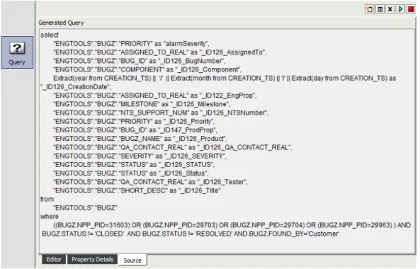
6.3 Understanding the Source View. . . 70
6.4 Understanding Property Text Substitution . . . 70
6.5 Setting up a Query using a Stored Procedure . . . . 71
6.6.1 Defining a Delta Query . . . 72
6.6.2 Defining a Custom Query . . . 72
6.7 Using Macro Expression Query Preprocessing . . . 72
6.7.1 Enabling Macro Expression . . . 74
6.7.2 Understanding Macro Expression Variables . . . 74
6.7.3 Defining Default Macro Expression Adapter Values . . . 75
6.7.4 Filtering Data Based on Date. . . 76
6.8 Clearing Queries . . . 77
6.9 Testing Queries . . . 77
6.10 Scheduling Queries . . . 77
6.10.1 Scheduling a Query . . . 78
6.10.2 Creating a Schedule . . . 79
6.10.3 Editing a Schedule . . . 80
6.10.4 Disabling a Schedule . . . 80
6.10.5 Clearing a Schedule . . . 80
6.10.6 Deleting a Schedule. . . 81
6.10.7 Triggering Schedules through Scripted Events . . . 81
6.10.8 Scheduling Queries at Adapter Startup and On Demand . . . 82
7 Importing and Exporting Adapter Definitions 83 7.1 Exporting Adapter Definitions. . . 83
7.1.1 Exporting an Adapter Definition . . . 83
7.1.2 Exporting an Adapter Definition for a Server without a Design-Time License . . . 84
7.2 Importing an Adapter Definition . . . 84
8 Deploying and Revoking Adapters 85 8.1 Deploying an Adapter Definition. . . 85
8.2 Undeploying Adapters . . . 85
8.3 Redeploying Adapters . . . 86
9 Customizing Deployed Adapters 87 9.1 Manually Configuring Alarm Column Names . . . 87
9.2 Using the Adapter’s Hierarchy File to Mine and Visualize Relationships . . . 88
9.3 Example: Mining and Visualizing Relationships . . . . 89
A Data Integrator Demo Definition 91 A.1 Configuring the Adapter Definition Demo. . . 91
A.1.1 Importing the Sample Adapter Definition . . . 91
A.1.2 Defining the Database Connection for the Sample Definition . . . 92
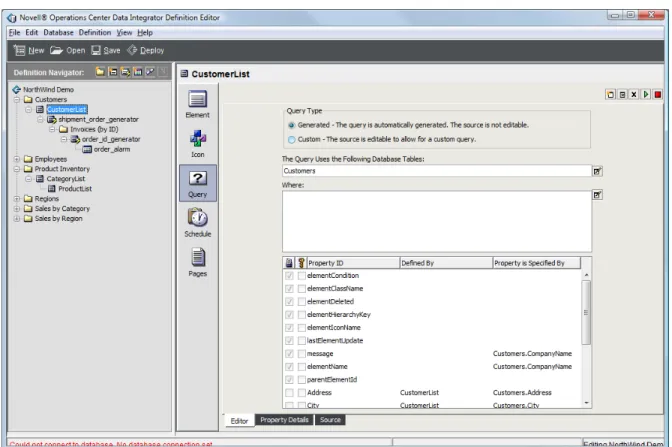
A.2 Examining the Adapter Definition Demo . . . 93
A.2.1 Looking at Basic Adapter Information . . . 94
A.2.2 Looking at Element Groups . . . 96
A.2.3 Looking at Database Elements . . . 97
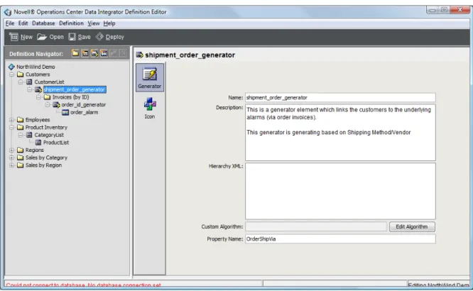
A.2.4 Looking at Generated Elements . . . 98
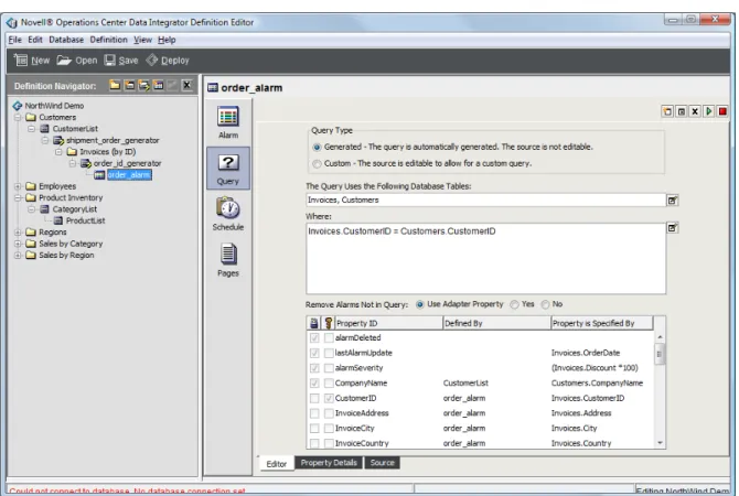
A.2.5 Looking at Alarm Definitions . . . . 99
6 Operations Center 5.0 Data Integrator Guide
B.5 December 2012 Patch Release . . . 102 B.6 June 2012 Patch Release . . . 102 B.7 February 2012 Patch Release . . . 102
About This Guide
The Data Integrator Guide provides instructions for administering the Data Integrator adapters.
Chapter 1, “Data Integrator Overview,” on page 9
Chapter 2, “Managing Adapter Definitions,” on page 13
Chapter 3, “The Data Integrator Definition Editor,” on page 27
Chapter 4, “Specifying Adapter Definition Properties,” on page 35
Chapter 5, “Defining Groups, Elements and Alarms,” on page 43
Chapter 6, “Defining Queries and Properties,” on page 61
Chapter 7, “Importing and Exporting Adapter Definitions,” on page 83
Chapter 8, “Deploying and Revoking Adapters,” on page 85
Chapter 9, “Customizing Deployed Adapters,” on page 87
Appendix A, “Data Integrator Demo Definition,” on page 91
Appendix B, “Documentation Updates,” on page 101
Audience
This guide is intended for system administrators who are responsible for setting up and
administering Data Integrator adapters within the Operations Center environment. It is assumed that
administrators are familiar with Operations Center and its user interface.
Feedback
We want to hear your comments and suggestions about this manual and the other documentation
included with this product. Please use the User Comments feature at the bottom of each page of the
online documentation.
Additional Documentation & Documentation Updates
This guide is part of the Operations Center documentation set. For the most recent version of the Data
Integrator Guide and a complete list of publications supporting Operations Center, visit our Online
Documentation Web Site at Operations Center 5.0 online documentation.
The Operations Center documentation set is also available as PDF files on the installation CD or ISO;
and is delivered as part of the online help accessible from multiple locations in Operations Center
depending on the product component.
Additional Resources
8 Operations Center 5.0 Data Integrator Guide
NetIQ Support Knowledgebase (https://www.netiq.com/support/kb/
product.php?id=SG_XOPERATIONSCENTER_1_2): A collection of in‐depth technical articles.
NetIQ Support Forums (https://forums.netiq.com/forumdisplay.php?26‐Operations‐Center): A
Web location where product users can discuss NetIQ product functionality and advice with
other product users.
Technical Support
You can learn more about the policies and procedures of NetIQ Technical Support by accessing its
Technical Support Guide (https://www.netiq.com/Support/
process.asp#_Maintenance_Programs_and).
Use these resources for support specific to Operations Center: Telephone in Canada and the United States: 1‐800‐858‐4000 Telephone outside the United States: 1‐801‐861‐4000 E‐mail: [email protected] ([email protected])
Submit a Service Request: http://support.novell.com/contact/ (http://support.novell.com/contact/ )
Documentation Conventions
In Novell documentation, a greater‐than symbol (>) is used to separate actions within a step and
items in a cross‐reference path. The > symbol is also used to connect consecutive links in an element
tree structure where you can either click a plus symbol (+) or double‐click each element to expand
them.
A trademark symbol (®, ™, etc.) denotes a Novell trademark. An asterisk (*) denotes a third‐party
trademark.
When a single pathname can be written with a backslash for some platforms or a forward slash for
other platforms, the pathname is presented with a forward slash to preserve case considerations in
1
1Data Integrator Overview
The Data Integrator is an optional component of the Operations Center platform and is licensed as a
separate product. Use the Data Integrator to leverage business metrics from databases, including
sales totals and help desk tickets, or analytics from business intelligence tools.
This guide explains how to define, configure, and deploy adapters using the Data Integrator. Use the
Data Integrator environment to leverage and analyze database information within Operations
Center. The Data Integrator adapter extracts data from specified sources and displays it in the
Operations Center console.
Section 1.1, “Overview,” on page 9
Section 1.2, “How does Data Integrator Work?,” on page 11
Section 1.3, “Development and Run Time Database Connections,” on page 12
1.1
Overview
Figure 1-1 Data Integrator Architecture Novell Operations Center
Integration Platform
Data Integrator
Data Integrator Adapter Data Integrator
Adapter
Data Integrator Adapter
10 Operations Center 5.0 Data Integrator Guide
Operations Center offers rich integrations with virtually any source of technology data. The Data
Integrator, which is an optional component of the Operations Center platform, extracts business
metrics from databases, including sales totals and help desk tickets, and also extracts analytics from
business intelligence tools.
The data extracted by a Data Integrator adapter is forwarded to the Operations Center platform for
correlation, analysis and visualization, and can be further leveraged through Service Views and the
dashboard.
Metrics from your data store can surface key performance indicators used by lines of business to
measure their success. Using Operations Center to correlate these metrics, such as cross‐referencing
daily sales and help desk tickets, can provide additional information. This information can then
populate real‐time executive dashboards that identify the service performance of applications. This is a true way of correlating business metrics with technology performance and availability. An
increase in calls to a call center or a drop in revenue can be significant warnings of technology
problems. Tying technology problems to their real business impact—such as the number of
customers who complain—provides an accurate way to prioritize.
Analyzing this information over time can even help identify trends, such as a drop in sales totals
when response time dips below a certain threshold. It can also assist in setting cost‐effective
performance thresholds for different geographies, customer groups and time periods.
Section 1.1.1, “Secure Access to Relevant Data,” on page 10
Section 1.1.2, “Point‐and‐Click Interface,” on page 10
Section 1.1.3, “Share Adapter Definitions,” on page 10
1.1.1
Secure Access to Relevant Data
Instead of wading through large volumes of data, the Data Integrator extracts only the data needed to
determine how technology is supporting the business. Also, the tool adheres to a database
environment’s security settings, so users cannot extract data, unless they have permission to do so.
1.1.2
Point-and-Click Interface
A point‐and‐click interface enables quick access to database information. Data Integrator
automatically discovers the available schemas in any relational SQL database, including DB2, Oracle,
SQL Server, and Sybase. Just point and click to select fields or values for integration, then specify the
time interval for capturing data, and how Operations Center should determine element or alarm
severity.
1.1.3
Share Adapter Definitions
The Data Integrator has a central management facility. Defined integrations can be stored and reused,
which is valuable to organizations with many instances of the same database distributed throughout
1.2
How does Data Integrator Work?
Data Integrator is an optional component of the Operations Center platform and requires a license
key.
The Data Integrator provides a development environment to define custom adapters that leverage
information from strategic and business databases.
Section 1.2.1, “Step 1. Define the Adapter Definition,” on page 11
Section 1.2.2, “Step 2. Deploy the Adapter Definition,” on page 11
Section 1.2.3, “Step 3. Create the Adapters,” on page 12
1.2.1
Step 1. Define the Adapter Definition
The first step is to create an adapter definition. Define everything about the adapter type—the
database it uses, the elements that are created, including their properties and icons, and which alarm
information is available.
The Data Integrator Definition Editor enables pointing and clicking through the process of defining
all aspects of the adapter definition. It reads the database schema and allows dragging and dropping
table names and table columns directly from the database schema in order to construct the adapter
definition.
Adapter definitions can be reused across organizations that have many instances of the same
database distributed throughout their environment.
1.2.2
Step 2. Deploy the Adapter Definition
The next step is deploying the adapter. Operations Center makes this new adapter definition
available as a run‐time adapter. When a user deploys an adapter, the deployed definition is included
in the Adapter Type drop‐down list.
1. Define
2. Deploy
12 Operations Center 5.0 Data Integrator Guide
1.2.3
Step 3. Create the Adapters
To leverage the new adapter, Admin users create adapter instances just as they create any other
Operations Center adapter. When started, the new adapter automatically leverages data from the
defined database and builds out all the elements, properties, and alarms. Everything is available in
the Elements hierarchy in the Operations Center console.
A deployed adapter definition can be edited and maintained based on changing needs or database
changes. However, changes do not take effect until the adapter definition is redeployed, thereby
protecting users against intermediate changes.
1.3
Development and Run Time Database Connections
The Data Integrator allows utilizing one database for development and another for adapter run time.
The following sections provide more information on specifying development and run‐time
databases:
Section 3.4, “Database Connections,” on page 30
Section 4.6, “Setting a Run‐Time Database Connection,” on page 41
Data Integrator is read‐only when interacting with a database. It does not write to the database. The Data Integrator supports JBDC drivers in general. Connection templates are provided for
commonly used databases. For more information about supported database connections, see “JDBC
Support in Data Integrator” in the Operations Center 5.0 Getting Started Guide.
To deploy JDBC drivers for other databases, contact Support (https://www.netiq.com/support/) to
have it signed, then save it to the /OperationsCenter_install_path/html/client/deploy
2
2Managing Adapter Definitions
The Data Integrator utilizes adapter definitions that instruct Operations Center how to create and
populate an adapter based on data stored in a relational database.
Section 2.1, “Understanding Adapters in Data Integrator,” on page 13
Section 2.2, “Creating Adapter Definitions,” on page 15
Section 2.3, “Validating an Adapter Definition,” on page 22
Section 2.4, “Renaming an Adapter Definition,” on page 23
Section 2.5, “Duplicating an Adapter Definition,” on page 24
Section 2.6, “Editing an Adapter Definition,” on page 24
Section 2.7, “Deleting an Adapter Definition,” on page 25
2.1
Understanding Adapters in Data Integrator
After deploying the adapter definition, you can create and start an adapter instance. A new branch of
the Elements hierarchy displays, representing the data from the relational database. This new
hierarchy consists of folders, elements, and alarm data.
Adapter definitions display in the Explorer pane under Administration > Adapters > Data Integrator.
They are not available as Operations Center adapters until they are deployed.
Figure 2‐1 illustrates adapter definitions displaying under the Data Integrator element:
14 Operations Center 5.0 Data Integrator Guide
The condition of an adapter definition alerts you to adverse changes. Table 2‐1 identifies the possible
conditions of an adapter definition: Table 2-1 Adapter Definition Conditions
The title bar also displays basic information about a selected adapter definition, including: Whether an edit session is open for the definition and the name of the user who is editing it Whether the definition is deployed as an adapter
The number of additional users viewing the definition in a read‐only state For example, in Figure 2‐2 an Admin user is editing the Support Issues definition: Figure 2-2 Explorer Pane and View Title Bar
No additional users are viewing the definition and there are no current deployments.
You can select an adapter definition element in the Explorer pane to view information in the title bar. Status Description
CRITICAL The adapter definition is orphaned. The edit session abruptly ended without a proper save performed.
MINOR The adapter definition is currently deployed.
INFO The adapter definition is currently being edited by a user.
2.2
Creating Adapter Definitions
The first step in creating a new adapter definition is to set up basic information about the adapter and
the database connection. The Create Adapter Definition wizard steps through these initial steps. To create an adapter definition:
1 In the Explorer pane, expand the Administration root element > Adapters.
2 Right‐click Data Integrator, then select Create Definition to open the Create Adapter Definition
dialog box:
3 In the Create Adapter Definition dialog box, specify an Adapter Name and Description:
Adapter Name: The name of the new adapter that is created when the definition is deployed.
When deployed, this is the name that the user selects from the Adapter Type drop‐down list in the
Create Adapter dialog box to create an adapter instance.
Description: Provides additional information about the definition. This description displays
when the mouse cursor is hovered over the adapter definition name under the Adapters
hierarchy.
16 Operations Center 5.0 Data Integrator Guide
5 Select the associated radio button to define a new connection, use an existing connection, or
define a new connection from an existing connection:
Define a new connection: Define a database connection that has not been used before with Data
Integrator. Continue to step 5.
Use an existing connection: Select an existing connection to use. Skip ahead to step 6.
Define a new connection from an existing connection: Define a new database connection by
modifying the properties of a current connection. Skip ahead to step 7. 6 Click Forward to continue.
7 Do one of the following:
If defining a new connection, specify a name for the database connection. Click Forward. If using an existing connection, select the connection you wish to use from the Database
drop‐down list. Click Forward and skip to step 9.
If defining a new connection from an existing connection, do the following:
1. Select the desired connection you wish to use from the Existing Connection drop‐down
list.
2. In the New Connection Name field, specify the name of the new connection. 3. Click Forward to continue.
8 If using an existing connection or creating a new connection from an existing connection, modify
the properties as required for connection.
Hostname: The database server name. Applies to all connection types except JDBC.
Port: The port number where the database listens for communications. Applies to all connection
types except JDBC.
18 Operations Center 5.0 Data Integrator Guide
JDBC Driver: The name of the class used to initiate a JDBC driver. Typically, the class name is in
a format similar to com.product.Driver. You can later hide this setting by not publishing the
value as an adapter property or allow the driver to be overwritten at deployment time. Applies
only to JDBC connections.
JDBC URL: Specifies how the driver connects to a JDBC database. Applies only to JDBC
Connections.
Time Stamp Query: At runtime, Data Integrator periodically queries the JDBC database for
availability. This query setting specifies how the database is queried to ensure it is available and
servicing requests. Applies only to JDBC Connections.
User Name: The name of the user account.
Password: The password associated with the user name.
Windows Domain: The name of the Windows domain to use for Windows native
authentication. Applies to JTDS and SQL Server connections.
For information about configuring the server for Windows Authentication, see Section 2.2.6,
“Configuring the Server for Windows Authentication,” on page 21.
Database Type: This value (Oracle, SQL Server, Sybase, DB2, and so on) is prefilled, based on
the selected database tab. For information about using a nondefault database driver, see
Section 2.2.5, “Using a Different Database Driver for a Data Source,” on page 21.
If you are creating or modifying a mySQL connection, see Section 2.2.1, “Notes on Connecting to
MySQL,” on page 19 and Section 2.2.4, “Signing a JDBC Driver,” on page 21.
If you are creating or modifying a JDBC connection, see Section 2.2.3, “Notes on Connecting to
JDBC,” on page 20 and Section 2.2.4, “Signing a JDBC Driver,” on page 21.
If you are creating or modifying an Oracle RAC connection, see Section 2.2.2, “Notes on
Connecting to Oracle RAC,” on page 19 and Section 2.2.4, “Signing a JDBC Driver,” on page 21.
9 Click Finish to complete the process and automatically open the Data Integrator Definition
Editor.
A new adapter definition displays in the Explorer pane under Administration > Adapters > Data
Integrator.
For basic information regarding using the Definition Editor and user preferences, see Chapter 3,
“The Data Integrator Definition Editor,” on page 27. This section also contains information
about changing development data source settings.
For information regarding Groups, see Section 5.2, “Defining Groups,” on page 45. For information regarding Database Elements, see Section 5.4, “Defining Elements from
Database Information,” on page 49.
For information regarding Generators, see Section 5.3, “Defining Dynamic Groups (Generator
Elements),” on page 47.
For information regarding alarms, see Section 5.5, “Creating Alarms,” on page 52.
The following sections are referenced for additional information from some of the preceding steps:
Section 2.2.1, “Notes on Connecting to MySQL,” on page 19
Section 2.2.2, “Notes on Connecting to Oracle RAC,” on page 19
Section 2.2.3, “Notes on Connecting to JDBC,” on page 20
Section 2.2.4, “Signing a JDBC Driver,” on page 21
Section 2.2.5, “Using a Different Database Driver for a Data Source,” on page 21
2.2.1
Notes on Connecting to MySQL
The MySQL JDBC driver is Open Source GPL (General Public License). To use this driver, download
it from http://dev.mysql.com/downloads/connector/j/3.1.html (http://dev.mysql.com/downloads/
connector/j/3.1.html). The driver must be placed in the following two locations, and one copy of the
driver must be signed for use in the Data Integrator:
The Operations Center server directory: /OperationsCenter_install_path/classes/ext.
Place the distributed driver as unsigned (unmodified).
The Operations Center console deployment directory: /OperationsCenter_install_path/ html/client/extensions. This copy must be signed. For more information, see Section 2.2.4,
“Signing a JDBC Driver,” on page 21.
2.2.2
Notes on Connecting to Oracle RAC
The following procedures describe various configuration information required to use Oracle RAC for
either the design‐time database or the adapter run‐time database. While the use of the JDBC OCI
provider is not required for the design‐time connection, it is required for the run‐time adapter. To specify an Oracle RAC database to use while creating (design‐time) the adapter definition:
1 Perform configuration steps as required for Oracle RAC on the Operations Center server. While it is not necessary to have the OCI package installed, all connections require the
ojdbc6.jar file to be manually deployed to the Operations Center server.
For instructions, see “Oracle RAC” in the Operations Center 5.0 Server Configuration Guide. 2 Define the database using the Generic JDBC Driver tab, and do the following:
2a Specify the following value for the JDBC Driver:
oracle.jdbc.driver.OracleDriver
2b Do one of the following to specify the JDBC URL:
To use the JDBC thin driver to connect to the Oracle RAC server, specify:
jdbc:oracle:thin:@(DESCRIPTION=(ADDRESS=(PROTOCOL=TCP)
(HOST=host1_ipaddress)(PORT=host1_portnumber)) (ADDRESS=(PROTOCOL=TCP) (HOST=host2_ipaddress)(PORT=host2_portnumber)) (LOAD_BALANCE=yes) (CONNECT_DATA=(SERVER=DEDICATED) (SERVICE_NAME=service_domain_name) (FAILOVER_MODE=(TYPE=SELECT)(METHOD=BASIC) (RETRIES=180)(DELAY=5))))
If the OCI package is installed on the client machine, do one of the following:
To use the JDBC OCI connection (supports FCF and Transparent Application Failover
(TAF), specify:
jdbc:oracle:oci:@racdb_configuration_name
or, if the connection is not defined in the tsnnames.ora file, specify:
jdbc:oracle:oci:@(DESCRIPTION=(ADDRESS=(PROTOCOL=TCP)
(HOST=host1_ipaddress)(PORT=host1_portnumber)) (ADDRESS=(PROTOCOL=TCP) (HOST=host2_ipaddress)(PORT=host2_portnumber))
(LOAD_BALANCE=yes)(CONNECT_DATA=(SERVER=DEDICATED)
20 Operations Center 5.0 Data Integrator Guide
To specify an Oracle RAC database to use for the run‐time adapter definition:
1 Perform configuration steps as required for Oracle RAC on the Operations Center server. The default database properties of the run‐time adapter must use the JDBC OCI provider. For instructions, see “Oracle RAC” in the Operations Center 5.0 Server Configuration Guide. 2 Define the database using the Generic JDBC Driver tab, and do the following:
2a Specify the following value for the JDBC Driver:
oracle.jdbc.driver.OracleDriver
2b Do one of the following to specify the JDBC URL:
If the service definition for the RAC connection is defined in the tsnnames.ora file,
specify:
jdbc:oracle:oci:@racdb_configuration_name
or, if the service definition for the RAC connection is not defined in the tsnnames.ora
file, specify:
jdbc:oracle:oci:@(DESCRIPTION=(ADDRESS=(PROTOCOL=TCP)(HOST=host1_ipadd ress)(PORT=host1_portnumber))(ADDRESS=(PROTOCOL=TCP)
(HOST=host2_ipaddress)(PORT=host2_portnumber))(LOAD_BALANCE=yes)(CONNE CT_DATA=(SERVER=DEDICATED)(SERVICE_NAME=service_domain_name)
(FAILOVER_MODE=(TYPE=SELECT)(METHOD=BASIC)(RETRIES=180)(DELAY=5))))
2c Specify the following query command for the Time Stamp Query:
select systimestamp from dual
2.2.3
Notes on Connecting to JDBC
To install the generic JDBC driver, locate the appropriate driver on a product distribution disk or
download it. The driver must be placed in the following two locations, and one copy of the driver
must be signed for use in the Data Integrator:
The Operations Center server directory: /OperationsCenter_install_path/classes/ext.
Place the distributed driver as unsigned (unmodified).
The Operations Center console deployment directory: /OperationsCenter_install_path/ html/client/extensions. This copy must be signed. For more information, see Section 2.2.4,
2.2.4
Signing a JDBC Driver
This information in this section is also available in the /OperationsCenter_install_path/html/ client/Readme.txt file. This Readme file describes the subdirectories in the /
OperationsCenter_install_path/html/client directory.
In the deploy directory, place patches or other .jar components that have been signed by
Operations Center. This directory is not be renamed when upgrading Operations Center versions, so
that its contents remain the same after upgrading.
Because of the tightened security model introduced by Oracle Java 7 Update 45, all .jar components,
including those from third‐parties, must be signed by Operations Center. Contact Support (https://
www.netiq.com/support/) to have the content signed.
2.2.5
Using a Different Database Driver for a Data Source
If there are multiple database drivers available on a machine and you want to use a specific database
driver, you can specify the exact driver to use in the Database Type connection parameter. However, if
the database driver should be used in the run‐time database connection, there is an additional step
that must be completed.
To change the default database driver:
1 When defining or editing a database connection, in the Database Type field, replace the value
with:
driver|url|timequery
where:
driver is the driver’s class name url is the JDBC URL string
timequery (for Oracle) is select sysdate from dual The pipe (|) characters are required.
2 If the driver is to be used for the run‐time database setting, in the database tab for top‐level
settings, insert the same string into the Database Type field.
If the Add to Adapter Page check box is selected for the Database Type, the setting is seen as the
default property value when using an instance of the adapter.
For more information about the database properties and run‐time database settings, see
Section 4.6, “Setting a Run‐Time Database Connection,” on page 41.
2.2.6
Configuring the Server for Windows Authentication
If you are using a JTDS or SQL Server connection with Windows Authentication, you must configure
the server for Windows Authentication.
To configure the server for Windows Authentication:
22 Operations Center 5.0 Data Integrator Guide
Add an associated domain user with appropriate permissions.
If MSSQL is setup to use an instance name, you must turn on the SQL Server Browser
Service. Then add the user to the instanceʹs security group.
2 To configure Operations Center for Windows Single Sign‐On (SSO), do the following: 2a Do one of the following to configure the Operations Center server:
On Unix: No native libraries required, but you must provide user, password. On Windows:
Native libraries are optional. If you donʹt use the native library, you must provide
user, password.
The domain user must be a member of the Windows Administrators group. 2b If running Operations Center as a service, the service must use the same domain user
account as the database.
If you are receiving an NT AUTHORITY\ANONYMOUS LOGON exception, verify that the account
used by the service and the database are the same.
2c Leave the User and Password properties blank (empty) for Data Integrator.
2d Leave the User, Password, and Domain adapter properties blank (empty).
2e Copy the /OperationsCenter_install_path/html/classes/win32/ntlmauth32.jar or
/OperationsCenter_install_path/html/classes/win64/ntlmauth64.jar file into the
/OperationsCenter_install_path/classes/ext directory. 2f Restart the Operations Center server.
2.3
Validating an Adapter Definition
At any time, obtain a validation report about an adapter definition which reports on information
about elements generated by the definition, identifies any problems with the definition, and statistics,
such as the number of error messages associated with the definition and the number of elements and
alarms defined.
To run a validation report on the adapter definition:
The validation report displays:
2.4
Renaming an Adapter Definition
All adapter definitions are located under Administration > Adapters > Data Integrator. It is possible to
rename a definition.
Definitions that are deployed or are currently edited cannot be renamed. Close all editors and
undeploy definitions before renaming an adapter definition. To rename an adapter definition:
1 In the Explorer pane, expand the Administration root element > Adapters > Data Integrator. 2 Right‐click a definition, then select Rename Definition to open the Rename Definition dialog box:
24 Operations Center 5.0 Data Integrator Guide
3 Enter a new name for the definition.
4 Click OK to apply the new name to the definition.
The definition is renamed (and resorted, if necessary) in the Explorer pane hierarchy.
2.5
Duplicating an Adapter Definition
All adapter definitions are found under Administration > Adapters > Data Integrator. Copy a definition
to create a definition with similar requirements. To duplicate an adapter definition:
1 In the Explorer pane, expand the Administration root element > Adapters > Data Integrator. 2 Right‐click a definition, then select Duplicate Definition:
A new copy of the selected definition is created under Administration > Adapters > Data Integrator
and is ready to be renamed and modified.
2.6
Editing an Adapter Definition
All adapter definitions are found under the Administration root element > Adapters > Data Integrator. The first concurrent edit session has read/write access to a definition. Subsequent concurrent edit
sessions have read‐only access to the definition. Changes made to a definition from a read‐only edit
session are not saved. To edit an adapter definition:
1 In the Explorer pane, expand the Administration root element > Adapters > Data Integrator. 2 Right‐click a definition, then select Edit Definition.
3 The Data Integrator Definition Editor opens.
For basic information regarding using the Definition Editor and user preferences and updating
the development data source, see Chapter 3, “The Data Integrator Definition Editor,” on
page 27.
For information regarding Groups, see Section 5.2, “Defining Groups,” on page 45. For information regarding Database Elements, see Section 5.4, “Defining Elements from
Database Information,” on page 49.
For information regarding Dynamic Groups, see Section 5.3, “Defining Dynamic Groups
(Generator Elements),” on page 47.
2.7
Deleting an Adapter Definition
All adapter definitions are found under the Administration > Adapters > Data Integrator tree. An
adapter definition must be undeployed in order to delete it. To delete an adapter definition:
1 In the Explorer pane, expand the Administration root element > Adapters > Data Integrator. 2 Right‐click a definition, then select Delete Definition.
3 Click Yes to confirm and delete the definition.
The definition is removed from the Administration > Adapters > Data Integrator hierarchy. 4 Close all editors and undeploy the definitions before trying to delete them.
3
3The Data Integrator Definition Editor
The Data Integrator Definition Editor is used to create and edit adapter definitions, as well as toquery and extract information from database tables and create elements and alarms in Operations
Center.
Section 3.1, “Understanding the Data Integrator Definition Editor,” on page 27
Section 3.2, “Opening the Definition Editor,” on page 28
Section 3.3, “Configuring User Preferences,” on page 29
Section 3.4, “Database Connections,” on page 30
3.1
Understanding the Data Integrator Definition Editor
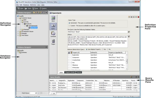
Figure 3‐1 shows the Data Integrator Definition Editor and its four panes:
28 Operations Center 5.0 Data Integrator Guide
The Definition Editor is comprised of these panes:
Definition Navigator: Use to create new groups, elements, generators, or alarm definitions. It
provides a hierarchical view of elements.
Database Navigator: The database schema is automatically read into the Data Integrator Editor,
and the Database Navigator pane provides a hierarchical list of views, database tables and
columns for the development database. Use the drag and drop feature to drag a table or column
to the Definition Properties pane to define new queries or properties assignments.
Definition Properties: Use to specify basic information about an adapter definition, including
adapter icons, run‐time adapter database connections and properties, and scripts that run based
on adapter activity.
Query Results: The adapter definition uses database queries to create elements and issue
alarms. The Query Results pane displays the output or an executed query.
You can use the buttons at the top of the Definition Editor dialog box to perform the following
functions:
New: Creates a new adapter definition.
Open: Opens a specified adapter definition in the Editor.
Save: Saves changes made to the definition. The Definition Editor has an auto‐save feature,
however you can click Save at any time.
Deploy: To implement changes made in the Definition Editor, click Deploy. The adapter is
restarted with the definition changes.
3.2
Opening the Definition Editor
1 In the Explorer pane, expand the Administration root element > Adapters > Data Integrator. 2 Right‐click an adapter definition, then select Edit Definition to open the Definition Editor.
The Definition Editor attempts to connect to the database. You can view the connection status in
3.3
Configuring User Preferences
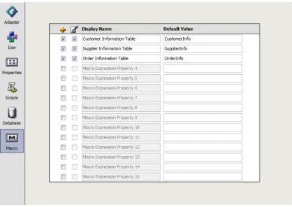
The Data Integrator User Preferences dialog box enables selecting various settings, including an auto‐
save feature and default maximum settings for queries. Figure 3-2 Data Integrator User Preferences Dialog
User preferences set auto‐save frequency and query defaults and maintain database connections. Set the following preferences for the Data Integrator Definition Editor:
Section 3.3.1, “Setting an Auto Save Frequency,” on page 29
Section 3.3.2, “Setting the Maximum Number of Table Rows Per Query,” on page 29
Section 3.3.3, “Setting the Maximum Time Allowed Per Query,” on page 30
Section 3.3.4, “Viewing Informational Messages When Using the Definition Editor,” on page 30
Section 3.3.5, “Deleting a Database Connection,” on page 30
3.3.1
Setting an Auto Save Frequency
1 In the Definition Editor, click Edit > User Preferences.
2 Use the Autosave Frequency spinner buttons to select the interval in minutes for the automatic
save feature to run.
3.3.2
Setting the Maximum Number of Table Rows Per Query
1 In the Definition Editor, click Edit > User Preferences.
2 Use the Maximum Rows Per Query spinner buttons to select the number of rows that are allowed
per query.
30 Operations Center 5.0 Data Integrator Guide
3.3.3
Setting the Maximum Time Allowed Per Query
1 In the Definition Editor, click Edit > User Preferences.
2 Use the Max Time Per Query spinner buttons to select the time in seconds that are allowed to
elapse per query.
Enter ‐1 to allow an unlimited amount of time.
3.3.4
Viewing Informational Messages When Using the Definition Editor
1 In the Definition Editor, click Edit > User Preferences.2 Select the Show Informational Messages check box to display alerts in specific cases.
For example, an informational message might be displayed in certain instances, such as when
trying to edit a definition that is read‐only or when a database connection must be defined. 3 (Optional) Deselect the Show Informational Messages check box to disable the message feature.
3.3.5
Deleting a Database Connection
1 In the Definition Editor, click Edit > User Preferences.
All database connection profiles are listed in the Database Connections list. 2 Select a database connection.
3 Click Delete to delete the database connection.
3.4
Database Connections
The adapter definition requires defining a database connection to access the database schema.
Because the Data Integrator is a tool for the development environment, the development database
connection could differ from the production database accessed at run‐time. You can define two
different database connections. For more information, see Section 4.6, “Setting a Run‐Time Database
Connection,” on page 41.
If you do not create and assign a schedule to the database element or alarm definition, the
If the current database connection is deleted for a definition currently being edited, then the current
connection remains in effect. The next time the definition is edited, a new database connection must
be defined.
Figure 3-3 Database Navigator Pane
View and use database schema to create queries for extracting element and alarm information into
Operations Center.
The following sections cover defining and testing a development database:
Section 3.4.1, “Viewing a Database Schema,” on page 31
Section 3.4.2, “Running a Sample Query,” on page 31
Section 3.4.3, “Changing the Development Data Source,” on page 32
Section 3.4.4, “Testing the Development Database Connection,” on page 34
3.4.1
Viewing a Database Schema
During the adapter definition creation process, a development database is defined as you specify
basic details in the Create Adapter Definition wizard. Data Integrator automatically discovers and
displays the database schema in the Database Navigator pane.
Click the plus (+) signs next to the database elements to open and explore the tables and columns of
the database schema.
3.4.2
Running a Sample Query
The Database Navigator pane provides a quick way to view sample data. Click a table, then click Run
32 Operations Center 5.0 Data Integrator Guide
3.4.3
Changing the Development Data Source
The development data source is specified as a step in the Create Adapter Definition wizard
(Section 2.2, “Creating Adapter Definitions,” on page 15).
After you have started to define and build out all the necessary element definitions for an adapter
definition, then changing databases is restricted to the same database type. For example, if an adapter
definition relies on an Oracle database, you can modify the adapter definition to use a different
Oracle database with the same table names, and so on. However, you cannot change to a different
database type, such as Sybase.
WARNING: If it is necessary to change the database type, close all Data Integrator Editor dialog
boxes and undeploy the definition before trying to change the database type. To change the development data source, do one the following:
“Changing the Development Data Source Using a New Database Connection” on page 32
“Changing the Development Data Source Using an Existing Database Connection” on page 33
“Changing the Development Data Source Using a New Connection Created from an Existing
One” on page 33
“Changing Settings for the Development Data Source” on page 33
“Refreshing the Connection to the Development Data Source” on page 33
Changing the Development Data Source Using a New Database Connection
1 In the Definition Editor, click Database > Open Connection to open the Update Business DataIntegration wizard.
2 Select the Define a New Connection radio button, then click Forward.
3 Specify the new name in the Database Name field, then click Forward to continue. 4 Specify the database parameters using the appropriate database tab:
Hostname: The database server name. Applies to all connection types except JDBC.
Port: The port number where the database listens for communications. Applies to all connection
types except JDBC.
Database: The database name (when defining a SQL Server, Sybase, or DB2 database
connection). Applies to all connection types except JDBC.
Server ID: The database name (when defining an Oracle database connection). Applies to all
connection types except JDBC.
JDBC Driver: The name of the class used to initiate a JDBC driver. Typically, the class name is in
a format similar to com.product.Driver. You can hide this setting by not publishing the value
as an adapter property or allow the driver to be overwritten at deployment time. Applies only to
JDBC connections.
JDBC URL: Specifies how the driver connects to a JDBC database. Applies only to JDBC
Connections.
Time Stamp Query: At runtime, Data Integrator periodically queries the JDBC database for
availability. This query setting specifies how the database is queried to ensure it is available and
servicing requests. Applies only to JDBC Connections.
Password: The password associated with the user name.
Windows Domain: The name of the Windows domain to use for Windows native
authentication. Applies to JTDS and SQL Server connections.
For information about configuring the server for Windows Authentication, see Section 2.2.6,
“Configuring the Server for Windows Authentication,” on page 21.
Database Type: This value (Oracle, SQL Server, Sybase, DB2, and so on) is prefilled based on
the selected database tab. For information about using a nondefault database driver, see
Section 2.2.5, “Using a Different Database Driver for a Data Source,” on page 21.
Changing the Development Data Source Using an Existing Database Connection
1 In the Definition Editor, click Database > Open Connection to open the Update Business DataIntegration wizard.
2 Select the Use an Existing Connection radio button, then click Forward.
3 Click the Connection drop‐down list, then select an existing database connection. 4 Click Forward to review or edit database settings.
Changing the Development Data Source Using a New Connection Created from
an Existing One
1 In the Definition Editor, click Database > Open Connection to open the Update Business Data
Integration wizard.
2 Select the Use a New Connection from an Existing Connection radio button, then click Forward. 3 Click the Existing Connection drop‐down list, then select an existing connection.
4 Enter the name for the new connection in the New Connection Name field, then click Forward. 5 Edit the prefilled parameters to customize the new connection.
6 Click Finish to save the new settings and use the new database.
Changing Settings for the Development Data Source
1 In the Definition Editor, click Database > Open Connection to open the Update Business Data
Integration wizard.
2 Click the Use an Existing Connection radio button, then click Forward.
3 Click the Connection drop‐down list, then select the current database connection. 4 Click Forward to review or edit database settings.
5 Click Finish to save the new settings and use the new database.
Refreshing the Connection to the Development Data Source
1 In the Definition Editor, click Database > Refresh Connection.34 Operations Center 5.0 Data Integrator Guide
3.4.4
Testing the Development Database Connection
1 In the Definition Editor, click Database > Test Connection. A confirmation message displays when the test is complete. 2 Click OK to close the message box.
4
4Specifying Adapter Definition Properties
For each adapter definition, there are basic properties and run‐time database information that mustbe defined. This includes specifying user‐defined adapter properties.
Section 4.1, “Specifying Adapter Definition Properties,” on page 35
Section 4.2, “Adapter Definition Properties,” on page 36
Section 4.3, “Assigning an Adapter Icon,” on page 37
Section 4.4, “Specifying Run‐Time Adapter Properties,” on page 38
Section 4.5, “Defining Script Triggers,” on page 40
Section 4.6, “Setting a Run‐Time Database Connection,” on page 41
4.1
Specifying Adapter Definition Properties
When setting up basic and necessary information for the adapter definition, the requirements are
organized in five main tabs:
Adapter: Specify basic descriptive information for the adapter. For more information, see
Section 4.2, “Adapter Definition Properties,” on page 36.
Icon: Specify an icon for the adapter from the Operations Center icon library or select a custom
icon. For more information, see Section 4.3, “Assigning an Adapter Icon,” on page 37.
Properties: Specify defaults for the run‐time adapter properties, including the alarm columns
displayed in the Operations Center console, and the adapter hierarchy file and stylesheet file.
For more information, see Section 4.4, “Specifying Run‐Time Adapter Properties,” on page 38. Scripts: Set up defaults for scripts that should run based on adapter activity. For more
information, see Section 4.5, “Defining Script Triggers,” on page 40.
Database: Specify the database connection that is used by the adapter at run‐time. For more
information, see Section 4.6, “Setting a Run‐Time Database Connection,” on page 41.
If you change adapter properties after deploying an adapter, it is necessary to stop and delete the
36 Operations Center 5.0 Data Integrator Guide
4.2
Adapter Definition Properties
Systems integrators or OEMs can use Data Integrator to create customized adapters for deployment
to multiple clients. Information in the adapter properties can describe the deployable product. For
internal use, the adapter properties could be used as part of an organization’s change control
mechanism.
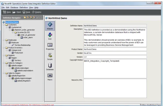
To specify basic properties for the adapter definition:
1 Select the adapter definition root element in the Definition Navigator pane.
2 The Adapter icon is selected by default and the Definition Properties pane shows basic properties
for the adapter definition.
3 Fill in the fields:
Definition Name: The name of the deployed adapter.
Description: A brief text description of the adapter definition.
Product Name: The name of the related product used to gather the data that is access by the
adapter.
Vendor: The vendor name of the specified product.
Version: The version number of the specified product.
4 Enter XML in the Hierarchy XML field.
The Hierarchy XML text area provides support for MODL (Managed Objects Definition
Language) <param> tags, custom properties, and other tags that are valid with a MODL
<generator> tag. You should know the XML syntax for what you want to accomplish.
MODL is an XML‐based markup language used to create HierarchyFiles for Operations Center.
The HierarchyFile reflects both the nature of information received from a management system
and the processing logic of the Operations Center system.
For more information about MODL and the HierarchyFile, see “Using the HierarchyFile” in the Operations Center 5.0 Adapter and Integration Guide.
4.3
Assigning an Adapter Icon
The icon specified at the adapter definition level is associated with the adapter element displayed
under Adapters in the Operations Center console. Select an adapter‐related icon from the Operations
Center Metamodel icon class browser. To specify an icon for an adapter:
1 Select the root element in the Definition Navigator pane. If you have just created the adapter, it is already selected. 2 In the right pane, click Icon to define icon properties:
3 Select a radio button:
Assign icon class from the Operations Center Metamodel: Uses an icon class from the
Operations Center Metamodel browser.
Next step: Click Browse Class, then select an icon class.
Define icon using custom graphics: Enables specifying custom small and large icon graphics. Next step: Click Choose or Import to select the graphic file for Small Icon and Large Icon. Imported
38 Operations Center 5.0 Data Integrator Guide
4.4
Specifying Run-Time Adapter Properties
Set default adapter property values through the adapter definition. You can also activate and display/ hide specific properties.
IMPORTANT: Do not manually edit the hierarchy for Data Integrator definitions. Always use the
Data Integrator Editor. Assume a defined Data Integrator adapter has a custom Hierarchy.XML file
specified in the adapter properties. If changes are made to the Data Integrator definition and the
definition is redeployed, Data Integrator overwrites the existing hierarchy file. To define run‐time adapter properties:
1 Select the adapter definition element in the Definition Navigator pane.
2 In the right pane, click the Properties icon to define run‐time adapter properties:
3 Select the (Activate Property) check box to enable the property for the adapter.
4 Select the (Add Property) check box to display the property in the run‐time adapter properties.
Leave it deselected to hide the property.
5 Enter default values for the properties where applicable:
Alarm Columns: The default alarm columns displayed in the Alarms view. Specify using the
Data Integrator property names or labels. To customize the Alarm Column name used in
Operations Center when deployed, specify as aliasname=propertyName.
Hierarchy File: A file in the /OperationsCenter_install_path/database directory that
contains an XML description of the element hierarchy to build below the adapter element.
Stylesheet File: The file in the /OperationsCenter_install_path/database directory that
applies to the HierarchyFile as a style markup to produce the final output.
Max Alarms: The maximum number of alarms allowed for the adapter. After reaching the
maximum number, the adapter ages out the oldest alarms based on the values set. Enter ‐1 to