Galaxy
3-48C, 3-144, 3-144C, 3-520, 3-520C
Installation Manual
Galaxy 3 Series Installation Manual
Table of Contents
Contents
Introduction ... 1-1
Variants ... 1-1
Section 1: Quick Setup ... 1-3
Section 2: System Architecture ... 2-1
PCB Layout ... 2-4
RS485 Expansion Module (G3-520 only) ... 2-5
System Installation and Wiring ... 2-6
Connecting the Galaxy 3 Series to the PSTN ... 2-7
Connecting Additional Telecom Apparatus... 2-8
Line Monitoring ... 2-8
Stand-by Battery ... 2-9
Battery Start-up ... 2-9
On-Board Power Supply Unit... 2-9
Memory ... 2-10
RS485 Data Communication Bus (AB Lines) ... 2-10
RS485 Wiring Configurations ... 2-10
RS485 Wiring Recommendations ... 2-11
Zones ... 2-13
Zone Addresses ... 2-13
Zone Addressing with Onboard RIO Switch ... 2-14
Wiring Zones ... 2-14
Preset 7 - 1k Fault Double-balanced (default) ... 2-15 Preset 8 - 1k Fault End-Of-Line ... 2-16
Wiring Keyswitches ... 2-16
Wiring Multiple Detectors ... 2-16
Wiring Terminator Buttons ... 2-17
Outputs ... 2-17
Output Applications ... 2-18
SPI Header ... 2-18
Section 3: Optional Modules and Facilities ... 3-1
Remote Input Output (RIO) Modules – C072... 3-1
Addressing ... 3-1
Connecting the RIO... 3-2
Galaxy 3 Series Installation Manual
Table of Contents
Configuring the RIO ... 3-2
Outputs ... 3-3
Entry/Exit RIO ... 3-3
Entry/Exit RIO Zone Programming ...3-4 Entry/Exit RIO Zone Operation ...3-4 Slave RIO ...3-4
RF RIO – C076 ... 3-5
Connecting the RF RIO ... 3-5
Addressing the RF RIO ... 3-6
Address Ranges ...3-6
RF RIO Programming ... 3-7
Configuring the RF RIO ... 3-7
Power Supply Unit ... 3-8
Configuration ... 3-8
Installation Instructions ... 3-9
Battery ... 3-10
Battery Test ... 3-10
Specifications ... 3-10
EN50131 Compliance... 3-10
Printer Interface Module-A134/A161 ... 3-11
Telecom Module – E062 ... 3-12
Connection to the PSTN ... 3-12
Programming the Telecom Module ... 3-12
RS232 Interface Module - E054 ... 3-13
Interface with a PC... 3-13
Serial Printer Interface ... 3-14
ISDN Module – E077 ... 3-15
Programming the ISDN Module ... 3-15
Ethernet Module - E080... 3-16
Configuring the Ethernet Module ...3-16
Ethernet Communication ... 3-16
Remote Servicing Suite... 3-17
Event Monitoring ... 3-17
Galaxy Gold... 3-17
User Management Suite ... 3-17
Section 4: The Galaxy Mk7 Keypad/KeyProx ... 4-1
General... 4-1
Power Consumption ... 4-1
Wiring the Keypad/KeyProx... 4-2
Addressing ... 4-2
Keypad/KeyProx Installation Procedure... 4-2
Galaxy 3 Series Installation Manual
Table of Contents
Volume Control ... 4-4
Adding a Keypad/KeyProx to the System... 4-4
Removing a Keypad/KeyProx from the System ... 4-4
Self Diagnostics ... 4-5
Keypad/KeyProx Operation ... 4-5
Number Keys ...4-5 View Keys ...4-5 Enter Key ...4-5 Escape Key... 4-6 Hash Key ...4-6 Star Key ... 4-6 Power LED ... 4-7 Display ...4-7The Galaxy KeyProx ... 4-8
General ... 4-8
Addressing ... 4-8
Operation... 4-8
Card Types ... 4-8
Section 5: Door Control Module - MAX3... 5-1
Introduction... 5-1
Standalone ... 5-1
On-line ... 5-1
Installing the MAX3 ... 5-1
MAX3 Pack ... 5-1
Mounting the MAX3... 5-1
Wiring the MAX3 ... 5-2
Configuring a MAX3 Reader into the System ... 5-3
Configuring as On-Line MAX3 ... 5-3
Configuring as a Stand-Alone MAX3 ... 5-4
Removing a MAX3 Reader from the System... 5-5
On-Line Mode...5-5
Operating Instructions ... 5-5
Card-Held Function ... 5-5 Card-Held System Setting ...5-5
MAX3 Log ... 5-6
Downloading the MAX3 Log ... 5-6
Dual Access Cards ... 5-7
Dual Focus (Card Held) ... 5-7
Timed Anti-Passback ... 5-7
Galaxy 3 Series Installation Manual
Table of Contents
Appendix A : Door Control - MAX (MX01) ... A-1
Installation Instructions ... A-1
Wiring the MAX ... A-1
Mounting the MAX ... A-2
Surface Mounting the MAX ... A-2 Flush Mounting the MAX ... A-2
Configuring a MAX Reader into the System ... A-3
Configuring as a Stand-Alone MAX ... A-3
Configuring as On-Line MAX ... A-4
Removing a MAX Reader from the System ... A-5
Stand Alone Mode ... A-5 On-Line Mode... A-5
Programming Instructions for On-Line Readers ... A-5
Operating Instructions (On-Line Modes) ... A-6
Gaining Access ... A-6 Card-Held Function ... A-6
Max Log ... A-7
Max Events Print-Out ... A-7
Appendix B: 3 Ampere Smart PSU - P015 ... B-1
Grounding ... B-1
Appendix C: Panel Comparisons ... C-1
Appendix D: Declaration of Conformity ... D-1
Compliance and Approvals ... D-1
EN50131 Compliance... D-2
PD6662 Compliance... D-2
Public Switched Telephone Network (PSTN) approval... D-2
Appendix E: Specifications ...E-1
Panel Specifications...E-1
Appendix F: Parts List Index ...F-1
Index ... 1
Galaxy 3 Series Installation Manual
Introduction
This manual gives full instructions required to install a Galaxy 3 Series control panel and associated peripherals.
Throughout this Installation Manual, references to menu options, unless otherwise indicated, are found in the Galaxy 3 Series Programming Manual, part number IP1-0053.
Variants
The Galaxy 3 Series is available in five variants: 3-48C; 3-144; 3-144C; 3-520; 3-520C. The differences between each variant are shown in the following table:
Introduction
Table 1-1. Galaxy 3 Series Variants
NOTE: The RS485 Expansion module gives two extra lines (lines 3 and 4) on the 3-520 only.
VARIANT ON-BOARDCOMMS RS485 EXPANSIONMODULE RS485 LINES
3-48C YES NO 1
3-144 NO NO 2
3-144C YES NO 2
3-520 NO YES 4
Galaxy 3 Series Installation Manual
Section 1: Quick Setup
To quickly set up a Galaxy 3 Series control panel for programming follow these simple steps:
1. Connect a 1k Ω (1%) resistor across each of the zones on the panel and any RIO’s (if connected). 2. Ensure that the tamper return loop — the terminal marked as AUX TAMP on the PCB — is a complete
loop.
NOTE: This is factory set as a completed loop with a 0 V return. 3. Connect a keypad to the AB LINE terminals on the control panel.
Table 1-2. Terminal Connections
4. Connect a 680 Ω End Of Line (EOL) resistor across the A and B terminals of the keypad. 5. Ensure that the keypad is fitted to the wall (see Keypad Installation Procedure, Section 4). 6. Connect the battery before replacing the control panel lid.
7. Connect the mains wiring to the control panel. Do not switch the mains ON. 8. Replace the control panel lid and secure the fastening screws.
9. Switch on the mains voltage (230 Va.c. / 50 Hz). 10.The following sequence of events occur:
• the keypad buzzer and control panel horn (if fitted) activate for 10 - 20 seconds,
• flashing is displayed on the keypad,
• the sounders stop and the keypad displays become blank,
• the green power LED lights and the following displays on the keypad
• the default banner is then displayed on the keypad.
where: XXX is the panel type
Y.YY is the panel software revision
11. The system is now ready to be programmed. Refer to Galaxy 3 Series Programming Manual: IP1-0053 for programming details.
Quick Setup
l e n a P l o r t n o C ) 1 e n i L ( Keypad 1 B B 1 A A - -+ + Configuring ConfiguringConfiguring ConfiguringConfiguring Please WaitPlease WaitPlease Wait
Please WaitPlease Wait
GALAXY <XXX> <VY.YY> GALAXY <XXX> <VY.YY>GALAXY <XXX> <VY.YY> GALAXY <XXX> <VY.YY> GALAXY <XXX> <VY.YY> 01:01
01:0101:01 01:01
Galaxy 3 Series Installation Manual
Section 2: System Architecture
G3-48 Configuration
Figure 2-1. Galaxy 3-48 System Configuration
On-board RIOs/ Smart PSUs/EN51 PSU Keypads Keyprox MAX
Galaxy Panel Zones Outputs Poss. Address Zones Outputs Poss. Address Poss. Address Poss. 3-48 (line 1) 16 8 4 2 - 5 32 16 8 0, 1 & 2, B, C, D, E, F 3 0, 1 & 2 4 16 zones on board Galaxy 3-48 Line 1 Keypads (8) CP027/ Keyprox (3) CP028 8 zones 4 outputs RIO (4) C072 8 zones 4 outputs OR NOTE:
The Telecom, Printer Interface, RS232, Ethernet and ISDN modules can only be connected to line 1.
If a Telecom module is attached, keypad address E cannot be connected to line 1(address E is shown as 18 on the system). If an RS232 module is attached, keypad address D cannot be connected to line 1 (address D is shown as 17 on the system). If an Ethernet module is attached, keypad address B cannot be connected to line 1 (address B is shown as 15 on the system). If an ISDN module is attached, keypad address C cannot be connected to line 1 (address C is shown as 16 on the system).
Cable run 1 km (max)
Certain keypad and max addresses can be replaced by a combined keyprox unit.
* *
*
NOTE:
Valid addresses for the keyprox are: Line 1 (0, 1 & 2).
This sets the address for both the keypad and card reader parts of the keyprox.
8 outputs on board on board telecom area Max (4) MX03 OR OR NOTE:
RIOs, RF RIO's and PSU's can be mixed on the lines. The maximum number of combined modules is given in the table below. * PSTN (comm 1) Smart PSU (4) P015 8 zones 4 outputs RF RIO Module (4) C076 Power Unit (4) P025 or Power RIO (4) P026 Printer Interface (1) A134/A161 Twisted Pair Screened Cable W002 ISDN Module (1) E077 (comm 3) RS232 Module (1) E054 (comm 2) Telecom Module (1) E062 (comm 5) Ethernet Module (1) E080 (comm 4) RS232 Serial Port (comm 6)
Galaxy 3 Series Installation Manual
On-board RIOs/ Smart PSUs/EN51 PSU Keypads Keyprox MAX
Galaxy Panel Zones Outputs Poss. Address Zones Outputs Poss. Address Poss. Address Poss.
144 (line 1) (line 2) 16 8 8 8 1 - 8 0 - 7 64 64 32 32 8 8 0 - 2, B, C, D, E, F 0 - 6, F 3 4 0-2 0-3 4 4
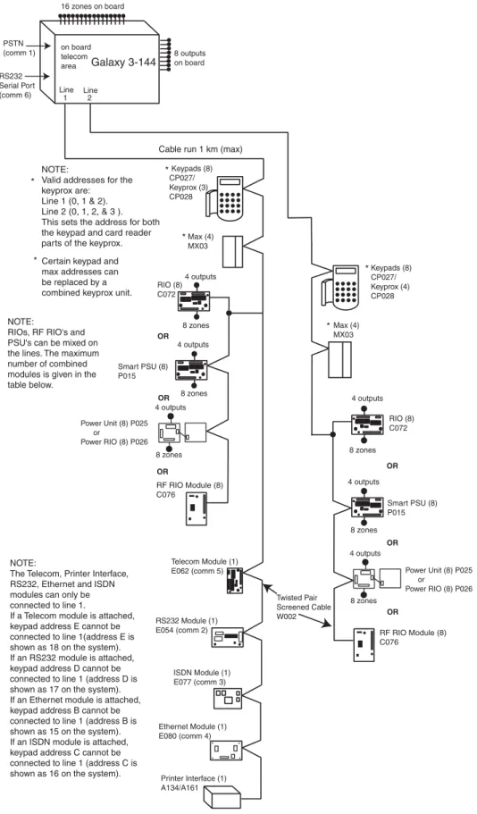
Figure 2-2. Galaxy 3-144 System Configuration
G3-144 Configuration
16 zones on board Galaxy 3-144 Line Line 1 2 Keypads (8) CP027/ Keyprox (3) CP028 Max (4) MX03 Keypads (8) CP027/ Keyprox (4) CP028 8 zones 4 outputs RIO (8) C072 8 zones 4 outputs OR 8 zones 4 outputs 8 zones 4 outputs Smart PSU (8) P015 RIO (8) C072 NOTE:The Telecom, Printer Interface, RS232, Ethernet and ISDN modules can only be connected to line 1.
If a Telecom module is attached, keypad address E cannot be connected to line 1(address E is shown as 18 on the system). If an RS232 module is attached, keypad address D cannot be connected to line 1 (address D is shown as 17 on the system). If an Ethernet module is attached, keypad address B cannot be connected to line 1 (address B is shown as 15 on the system). If an ISDN module is attached, keypad address C cannot be connected to line 1 (address C is shown as 16 on the system).
Cable run 1 km (max)
Certain keypad and max addresses can be replaced by a combined keyprox unit. * * * * * NOTE:
Valid addresses for the keyprox are: Line 1 (0, 1 & 2). Line 2 (0, 1, 2, & 3 ). This sets the address for both the keypad and card reader parts of the keyprox.
8 outputs on board on board telecom area Max (4) MX03 OR OR OR RF RIO Module (8) C076 OR OR NOTE:
RIOs, RF RIO's and PSU's can be mixed on the lines. The maximum number of combined modules is given in the table below. * PSTN (comm 1) RS232 Serial Port (comm 6) 8 zones 4 outputs Power Unit (8) P025 or Power RIO (8) P026 Smart PSU (8) P015 8 zones 4 outputs RF RIO Module (8) C076 Power Unit (8) P025 or Power RIO (8) P026 Twisted Pair Screened Cable W002 Printer Interface (1) A134/A161 ISDN Module (1) E077 (comm 3) RS232 Module (1) E054 (comm 2) Telecom Module (1) E062 (comm 5) Ethernet Module (1) E080 (comm 4)
Galaxy 3 Series Installation Manual
On-board RIOs/ Smart PSUs/EN51 PSU Keypads Keyprox MAX
Galaxy Panel Zones Outputs Poss. Address Zones Outputs Poss. Address Poss. Address Poss.
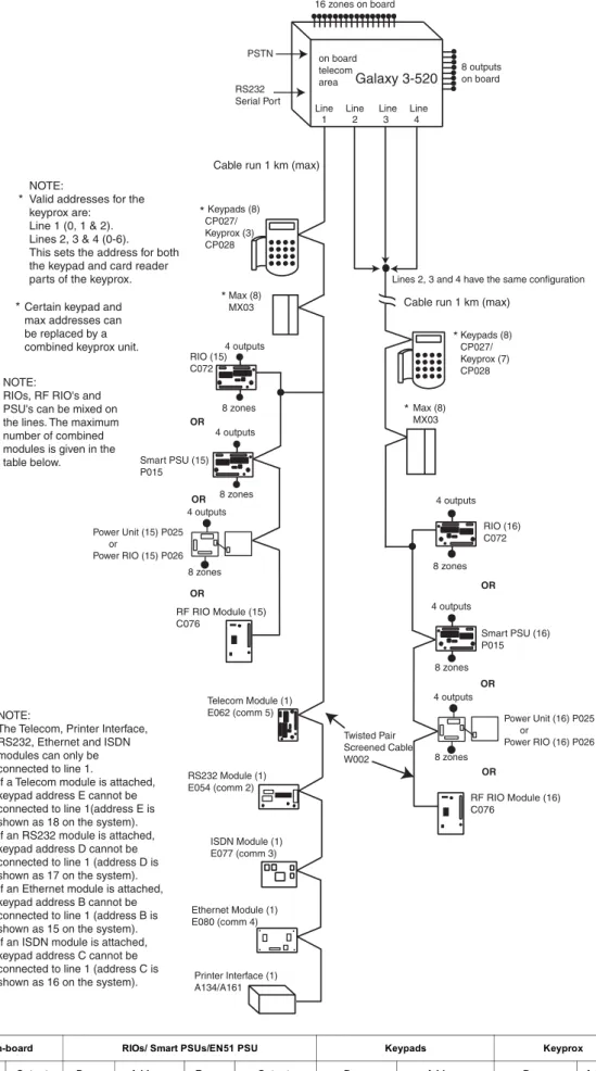
520 (line 1) (lines 2, 3, 4) 16 8 15 16 1 - 9, A - F 0 - 9, A - F 120 384 60 64 8 8 0 - 2, B, C, D, E, F 0 - 6, F 3 7 0-2 0-6 8 8 Figure 2-3. Galaxy 3-520 System Configuration
G3-520 Configuration
Galaxy 3-520 Line Line Line Line
1 2 3 4 Keypads (8) CP027/ Keyprox (3) CP028 Max (8) MX03 Keypads (8) CP027/ Keyprox (7) CP028 8 zones 4 outputs RIO (15) C072 8 zones 4 outputs OR 8 zones 4 outputs 8 zones 4 outputs Smart PSU (16) P015 RIO (16) C072 Twisted Pair Screened Cable W002 Cable run 1 km (max)
Cable run 1 km (max)
Lines 2, 3 and 4 have the same configuration
RF RIO Module (16) C076
Certain keypad and max addresses can be replaced by a combined keyprox unit. * * * * * NOTE:
Valid addresses for the keyprox are: Line 1 (0, 1 & 2). Lines 2, 3 & 4 (0-6). This sets the address for both the keypad and card reader parts of the keyprox.
16 zones on board 8 outputs on board on board telecom area Max (8) MX03 OR OR OR OR OR NOTE:
RIOs, RF RIO's and PSU's can be mixed on the lines. The maximum number of combined modules is given in the table below. * RS232 Serial Port PSTN 8 zones 4 outputs Power Unit (16) P025 or Power RIO (16) P026 Smart PSU (15) P015 8 zones 4 outputs RF RIO Module (15) C076 Power Unit (15) P025 or Power RIO (15) P026 Printer Interface (1) A134/A161 ISDN Module (1) E077 (comm 3) RS232 Module (1) E054 (comm 2) Telecom Module (1) E062 (comm 5) Ethernet Module (1) E080 (comm 4) NOTE:
The Telecom, Printer Interface, RS232, Ethernet and ISDN modules can only be connected to line 1.
If a Telecom module is attached, keypad address E cannot be connected to line 1(address E is shown as 18 on the system). If an RS232 module is attached, keypad address D cannot be connected to line 1 (address D is shown as 17 on the system). If an Ethernet module is attached, keypad address B cannot be connected to line 1 (address B is shown as 15 on the system). If an ISDN module is attached, keypad address C cannot be connected to line 1 (address C is shown as 16 on the system).
Galaxy 3 Series Installation Manual
PCB Layout
PCB Layout
Figure 2-4. PCB Layout LID T AMP +12V +12V +12V +12V 1 2 3 4 2 AU X T AMP G N D RX TX B2 A2 A1 B1 +12V PHONE LINE A B A B AC MICR O PR OCESSOR T elecom Socke t 16 on-board z ones Exter nal loudspeak er Leads f o rlid tamper micros
w itch RS232 P o rt J u mper Lead fo r off-w all tamper s w itch RS485 line 1 RS485 line 2 (3-144/3-520 only) T elecom Connect Batter y ter m inals
Expansion card interf
ace Hor n output volume control RIO 0 13 RIO 1 GND GND +12V CTS RT S LED1(f o r T e lecoms) LED2 (f or RS232) LK5 LK3 +12V 4 14.5 +BA T -BA T F1 F2 BA T BELL F4 A UX1 A UX2 (3-144/3-520 only) FLASH SRAM SPI Pro gra m Header OFF WALL T AMPER BA TTER Y ST AR T UP 1 2 3 4 5 6 7 8 SW3 RIO SWITCH Engineer soc k e t (RS485 Line1) Engineer soc k e t (RS485 Line 2) NO TE: Fuse A UX1 controls RS485 line 1, RIO 0 (z ones 1-8) Fuse A UX2 controls RS485 line 2, RIO 1 (z ones 1-8) RS232 P o rt soc k e t Memor y bac kup batter y Pull-up s w itches Rela y Output N/O C N/C ONON NO TE:
Zones 1-8 (RIO 0 line 1) Zones 1-8 (RIO 1 line 1 (s
witch SW3-8 OFF))
OR
Zones 1-8 (RIO 1 line 0 (s
witch SW3-8 ON)) 1 2 0V 3 4 0V RIO 0 5 6 0V 7 8 0V 1 2 0V 3 4 0V RIO 1 5 6 0V 7 8 0V F3 3-144/3-520 only
Galaxy 3 Series Installation Manual
The 7 transistorised outputs on the Galaxy 3 Series can be configured to open collectors by setting the dip switch SW3 to the OFF position.
NOTE: Output 2 on RIO 0 (relay output) is not affected.
The following table shows which outputs are controlled by which switches.
Table 2-1. SW3 Transistorised Outputs Control
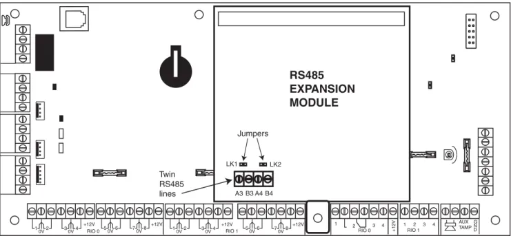
RS485 Expansion Module (G3-520 only)
The RS485 Expansion Module can be attached to the G3-520 to give 2 extra RS485 (AB) lines. The Expansion module must be wired in a daisy-chain configuration. That is, the A line from the previous module is connected to the A3 or A4 terminal of the Expansion Module.
The RS485 (AB) line must have a 680 ohm resistor fitted across the A and B terminals of the last module on the line. If two lines are connected, both ends must be terminated with a 680 ohm resistor and the appropriate link (LK1 or LK2) removed.
RS485 Expansion Module
Figure 2-5. RS485 Expansion Module
+12V +12V +12V +12V 1 2 3 4 2 AUXTAMP G N D RIO 0 1 3 RIO 1 +12V 4 1 2 0V 30V4 RIO 0 50V6 70V8 10V2 30V4 RIO 1 50V6 70V8 A4 RS485 EXPANSION MODULE Jumpers LK1 LK2 Twin RS485 lines A3 B3 B4 (SW3) RIO Output 1 0 1 2 0 3 3 0 4 4 1 1 5 1 2 6 1 3 7 1 4
Galaxy 3 Series Installation Manual
System Installation and Wiring
The installation and wiring must be performed by a competent engineer. For permanently connected equip-ment, a readily accessible disconnect device must be incorporated in the fixed wiring having contact separation of at least 3 mm on each pole. The Galaxy 3 Series control panel must be connected to the a.c. mains supply (230/240 Va.c. 50 Hz) via a fused connection outlet.
The fuse in the mains outlet must not exceed 3A.
WARNING: A means of isolation from the mains supply must be provided within 2 metres of the control panel. Where live and neutral supplies can be identified, a fused spur with a 3 amp fuse, must be fitted on the live circuit. Where live and neutral circuits cannot be reliably identified, 3 amp fuses must be fitted to both circuits.
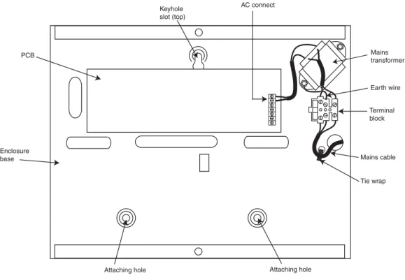
Route the mains cable through the hole on the right hand side of the enclosure base. Securely anchor the cable to the box using the tie-wrap as shown in the following Figure:
Figure 2-6. Securing the Mains Cable to the Enclosure Base
Secure the panel base to the wall using three 1.5" No. 8 round head steel screws through the holes provided. The mains cable used must be a three core type (with green/yellow earth insulation) of adequate current carrying capacity.
NOTE: The mains cable must satisfy the requirements stated in BS6500. Connect the mains cable to the mains terminal block as follows:
• blue wire to the terminal marked N (Neutral) • green/yellow wire to the terminal marked (Earth) • brown wire to the terminal marked L (Live)
NOTE: No other connections to the mains connector are permitted.
All wiring must be in accordance with the latest edition of the IEE Wiring Regulations, BS7671 (Requirements for Electrical Installations).
Installation Recommendations
Tie wrap Mains cable Terminal block Earth wire Mains transformer AC connect Keyhole slot (top) PCB Enclosure baseGalaxy 3 Series Installation Manual
Connecting the Galaxy 3 Series to the PSTN
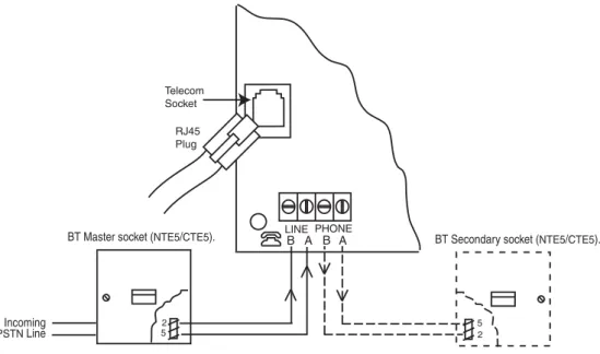
The Telecommunications Network Voltage (TNV) port (terminals A and B on PCB) must be permanently connected (hard-wired) to the PSTN via a BT master socket, refer to Figure 2-7.
Note: If the BT master socket is the newer type (NTE5/CTE5), then the connection can be carried out by the installation engineer. If the BT master socket is not an NTE5/CTE5, then the network operator must make the connection.
System Wiring
Figure 2-7. Connecting the Galaxy 3 Series to the PSTN
NOTES: 1. Terminals 2 and 5 on the BT Master Socket must be hard-wired to LINE A and B terminals on the Galaxy 3 Series PCB. The connection is polarity independent.
2. It is strongly recommended that the Galaxy 3 Series panel is the only device on the line. 3. If another device is to be connected to the line, connect the PHONE terminals on the PCB
to terminals 2 and 5 on a second BT Master Socket.
There are two methods of connecting the on-board Telecom Module to the PSTN:
Method 1
Using cable suitable for connection to 2.8 mm diameter screw terminals, strip back approximately 20 mm of the outer sheath and then remove approximately 4 mm of the insulation from the wires to be connected to the Galaxy 3 Series PCB.
Connect terminals 2 and 5 on the BT Master socket across the LINE A and B terminals on the Galaxy 3 Series PCB, see Figure 2-7.
Method 2
Use a standard cable with RJ45 plug on one end and plug into the telecom socket on the Galaxy 3 Series PCB. Connect the other end of the cable to the BT Master socket as described in Method 1.
PHONE LINE A B A B Incoming PSTN Line 2 5
BT Master socket (NTE5/CTE5). BT Secondary socket (NTE5/CTE5). Telecom Socket RJ45 Plug 5 2
Galaxy 3 Series Installation Manual
Connecting Additional Telecom Apparatus
A BT secondary socket, allows additional telecom apparatus to be connected in series with the on-board telecom module. Connect the PHONE terminals A and B on the PCB to the terminals on the BT secondary socket. See Figure 2-7.
System Wiring (cont’d)
Line Monitoring
Under normal idle state conditions, the on-board Telecom Module monitors the RS485 line. The communica-tion status is indicated by the state of the red LED (LED1) as shown in the following table:
E T A T S D E L INDICATION F F O D E L Nod.c.supplytomodule s 9 . 0 -F F O , s 1 0 -N O Normalcommunicaiton ll a c f o d n e t a e s l u p e l g n i S Normalcommuncaiton ll a c m r a l a f o d n e t a g n i h s a l F FaliedCommunicaiton y x a l a g , g n ir o ti n o m m r a l a g n ir u d n O S M S d n a d l o g NormalCommunicaiton , g n ir o ti n o m m r a l a g n ir u d g n ir e k c il F S M S d n a d l o g y x a l a g Poorcommunicaiton l a n g i s g n i g n ir h ti w e m it n i s e h s a l F LineRinging d e ll a i d s i ti g i d h c a e s a s e s l u P Nmoarkminaglicnadillcaitonwhen Table 2-2. Comms Status
Galaxy 3 Series Installation Manual
Stand-by Battery
The Galaxy 3 Series control panels can accommodate up to 2 x 17 Ahr batteries. Ensure that the battery connector leads on the control panel Powers Supply Unit (PSU) are connected to the correct terminals on the battery.
CAUTION: There is a risk of explosion if the battery is replaced by an incorrect type. Dispose of used batteries according to the instructions.
Table 2-3. Battery/Control Panel connections
Battery Start-up
The system can be powered up via the Battery Start-up jumper if there is no AC power. To do this, short out the Battery Start-up jumper for the duration of the configuration process only. Never leave the Battery Start-up connected or else deep discharge of the Stand-by Battery will occur.
On-Board Power Supply Unit
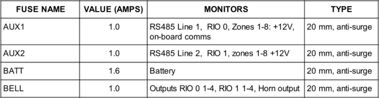
The on-board Power Supply Unit (PSU) supplies and monitors power to the system and peripherals. The following table shows the fuse name and value in amps.
G3-144/G3-520: The Galaxy 3 Series control panel contains four fuses. Details are given in the table below. NOTE: The G3-48 does not require fuse AUX2.
Table 2-4. On-board PSU Fuses Power Monitoring Characteristics: Low battery level: 11.2V
Deep discharge protection: 10.5V Overvoltage protection: 14.7V
Stand-by Battery
l e n a P l o r t n o C Battery T A B - -veterminal T A B + +veterminalFUSE NAME VALUE (AMPS) MONITORS TYPE
AUX1 1.0 RS485 Line 1, RIO 0, Zones 1-8: +12V, on-board comms
20 mm, anti-surge AUX2 1.0 RS485 Line 2, RIO 1, zones 1-8 +12V 20 mm, anti-surge
BATT 1.6 Battery 20 mm, anti-surge
BELL 1.0 Outputs RIO 0 1-4, RIO 1 1-4, Horn output 20 mm, anti-surge
G3-48
The PSU total capacity is 1.5A. Internally the PSU is split in two in order to ensure sufficient current is always available for stand-by battery recharge. The PSU capacity is broken down as follows:
• Battery: 0.75A
• Control PCB: 0.25A
• AUX +12V: 0.5A
G3-144/520
The PSU total capacity is 2.5A. Internally the PSU is split in two in order to ensure sufficient current is al-ways available for stand-by battery recharge. The PSU capacity is broken down as follows:
• Battery: 1.25A
• Control PCB: 0.25A
• AUX +12V: 1.00A
Galaxy 3 Series Installation Manual
Figure 2-8. Daisy Chain Configuration
Memory
The Galaxy 3 Series control panel is fitted with a memory chip with its own battery backup on the main PCB. This allows the panel to retain the system configuration, programming details and the event log for up to a year when both the mains power and standby battery have been disconnected. The memory backup battery must be kept in place to retain the memory during a mains failure. Re-apply power, this is known as a warm start. To completely erase the system memory and return to the default settings, place a piece of thin card between the retaining clip and the memory backup battery then remove all power to the PCB for one minute. Re-apply power and remove the card. This is known as a cold start.
The memory backup battery shoud be replaced every 5 years.
CAUTION: There is a risk of explosion if the battery is replaced by an incorrect type. Dispose of used batteries according to the instructions.
CAUTION: Do not overstress the retaining clip when removing and installing the backup battery. The clip must maintain a firm pressure on the backup battery at all times.
RS485 Data Communication Bus (AB Lines)
Communication between the Galaxy control panels and the modules attached to the system takes place on the AB lines. The communication protocol is RS 485 format. The control panel constantly monitors the modules attached to it. A break in the communication from any of the modules generates a module tamper alarm
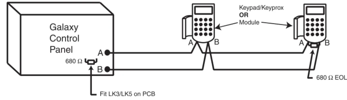
RS485 Wiring Configurations
The system must be wired in a daisy-chain configuration. That is the A line from the previous module is connected to the A terminal of the current module and then on to the A line of the next module.
The RS485 (AB) line must have a 680 Ω resistor fitted across the A and B terminals of the last module on the line. If two lines are connected, both ends must be terminated with 680 Ω resistors and the appropriate link (LK3 or LK5) removed.
Each AB line can run in two directions from the control panel. • Remove link LK3 (RS485 line1) or link LK5 (RS485 line2). • Run two lines from the A and B terminals of the line.
• Terminate both Ends of Line (EOL) with a 680 ohm resistor.
NOTE: It is permissable to have different configurations on each line. For example, line 1 - Daisy chain; line 2 - twin AB daisy chain.
Memory
Galaxy Control Panel 680 Ω Fit LK3/LK5 on PCB A B A B 680 Ω EOL A B Keypad/Keyprox OR ModuleGalaxy 3 Series Installation Manual
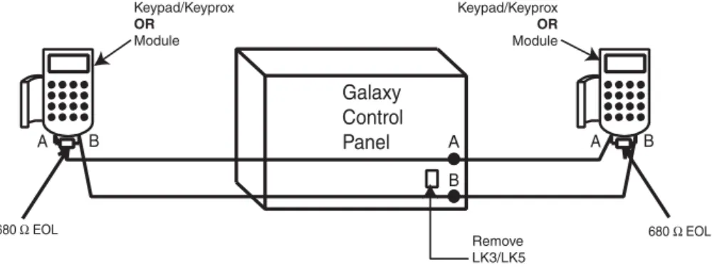
2. The system must be wired in a daisy-chain configuration. Spur and star configurations must not be used as they reduce the immunity to electrical interference.
3. The cable used to connect the RS485 (AB) line must be screened twisted pair (Part No. W002) or Belden 8723 equivalent.
4. Shielded twisted pair cable, where used, is connected to the earthing pillar on the Galaxy control panel using the P-clip and nut supplied (refer to Figure 2-10).
5. The RS485 (AB) line must have a 680 Ω resistor fitted across the A and B terminals of the last
module on the line. If twin lines are connected, both ends must be terminated with 680 Ω resistors and the appropriate link on the control panel PCB must be removed (refer to figure 2-9).
Figure 2-9. Twin AB Line Daisy-Chain configuration
RS485 Wiring Recommendations
To ensure that the system communicates at the maximum level of efficiency, the following recommendations must be adhered to:
1. Each communication line can support 32 devices. The maximum number of devices on each line are:
Table 2-5. Communication Devices
RS485 Recommendations
A B A B Galaxy Control Panel 680 Ω EOL 680 Ω EOL A B Keypad/Keyprox OR Module Keypad/Keyprox OR Module Remove LK3/LK5 Galaxy 3-48 (Line 1 only) Galaxy 3-144 (Lines 1-2) Galaxy 3-520 (Lines 1-4)Keypads 8 8 per line 8 per line
Keyprox 3 4 (line 2)3 (line 1) 7(lines 2, 3, 4)3 (line 1)
RIO's/SPSU's 4 8 per line 15 (line1)
16 (lines 2, 3, 4)
RF RIO 4 8 per line 15 (line 1)
16 (lines 2, 3, 4)
MAX 4 4 per line 8 per line
RS232 1 1 (line 1 only) 1 (line 1 only)
Telecoms 1 1 (line 1 only) 1 (line 1 only)
Printer 1 1 (line 1 only) 1 (line 1 only)
ISDN 1 1 (line 1 only) 1 (line 1 only)
Galaxy 3 Series Installation Manual
RS485 Recommendations
6. There must only be a single AB pair of wires in each of the cables.
7. The minimum voltage level is 10.5 Vd.c. with 12.5 Vd.c. being the recommended working minimum. 8. The power supply in the Galaxy control panel and remote power supplies must not be connected
in parallel.
9. The 0 V of all remote power supplies should be connected in common to the 0 V of the Galaxy control panel.
10. Ensure that any extension loudspeakers are not wired in the same cable as an AB pair of wires. 11. Where possible, ensure that the AB cable is at least 30 centimetres away from any other cables. 12. Where possible, ensure that the AB cable does not run parallel to other cables for extended
distances (maximum 5 metres).
Figure 2-10. Connection of cable screen using P-Clip
A B AB connectors RS 485 cable data line data line P-clip Cable screen Nut P-clip Earthing pillar (threaded)
Galaxy 3 Series Installation Manual
Zones
The default setting for the zones on the Galaxy 3 Series are shown in the following table:
Table 2-6. Default Zone Functions
Zone Addresses
Each zone has a four digit address; 1004, 4136. The address is made up of three reference numbers as shown in the following figure:
Figure 2-11. Zone Addresses
For example, zone 3057 is the detector connected to line 3, RIO 05, zone 7.
Zone Addresses
Example: 3057 Represents Panel Line No. Represents RIO Address Represents Zone No. 1-8 on RIO GALAXY G3 PANEL 1 2 3 4 RIO ADDRESS 05 ZONE 7 3 05 7 GalaxyPanel Zone 1001 Zone 1002
Remaining Zones
3-48 Final Exit Intruder
3-144 Final Exit Intruder
Galaxy 3 Series Installation Manual
Table 2-8. Double Balanced Zone Resistance and Conditions Table 2-7. Zone Address Ranges
Wiring Zones
The zones on Galaxy 3 Series panels can be Double Balanced (default) or End of Line. Zones can be pro-grammed with different resistance ranges for zone status activation (see Galaxy 3 Series Programming Manual, IP1-0053, parameter 51.46 = Parameters.Zone Resistance). Refer to Table 2-8 (Double Balanced) or Table 2-9 (End of Line) for details of the zone resistance and resulting conditions.The system default is preset 7, giving fault monitoring on 1k double balanced wiring.
NOTE: The circuit debounce time (the period the zone must remain in a state to register a change in condi-tion) is 300 milliseconds by default.
Zone Addressing with Onboard RIO Switch
The RIO switch (SW3, dipswitch 8) controls the ordering of the on-board RIO’s. This dipswitch must be set before powering up the panel. Setting the switch to ON allows a RIO addressed as 1 to be connected to line 1, giving a total of 8 RIO’s on a G3-144 and 15 RIO’s on a G3-520.
NOTE: The RIO switch is not functional on the G3-48. It defaults to the Switch off configuration.
Switch off (default)
When the switch is set to this mode, the onboard RIO’s configure to the following addresses:
Onboard RIO0 Zone address range: 1001-1008 Outputs: 1001-1004
Onboard RIO1 Zone address range: 1011-1018 Outputs: 1011-1014
Switch on
When the switch is set to this mode, the onboard RIO’s configure to the following addresses:
Onboard RIO0 Zone address range: 1001-1008 Outputs: 1011-1014
Onboard RIO1 Zone address range: 0011-0018 Outputs: 0011-0014
RIO Switch
Panel On-Board Zone Address Ranges Total on-board Zones Max No of External RIO's (Line 1) Valid External RIO Addresses (Line 1) Total Zone Addresses (Switch ON) 3-48 1001 - 1008, 1011 - 1018 16 4 2 - 5 48 3-144 1001 - 1008, 1011 - 1018 (switch off) 16 7 2 - 8 144 1001 - 1008, 0011 - 0018 (switch on) 16 8 1 - 8 3-520 1001 - 1008, 1011 - 1018 (switch off) 16 14 2 - 9, A - F 520 1001 - 1008, 0011 - 0018 (switch on) 16 15 1 - 9, A - F
Preset 1 - 1k Preset 2 - 2k2 Preset 3 - 4k7 Preset 7 - 1k
Fault Tamper S/C 0 - 800 0 - 1800 0 - 3700 0 - 800 Low Res 800 - 900 1800 - 2000 3700 - 4200 800 - 900 Normal 900 - 1200 2000 - 2500 4200 - 5500 900 -1200 High Res 1200 - 1300 2500 - 2700 5500 - 6500 1200 - 1300 Open 1300 - 12000 2700 - 12000 6500 - 19000 1300 - 3500 Fault - - - 3500 - 4500 Masked 12000 - 19000 12000 - 15000 19000 - 22000 4500 - 19000 Tamper O/C 19000 - infinity 15000 - infinity 22000 - infinity 19000 - infinity
Galaxy 3 Series Installation Manual
Table 2-9. End of Line Zone Resistance and Conditions
Figure 2-12. Preset 7 - Double balanced 1k Fault Monitoring Wiring
Zone 1k 100 m Tamper N/C 1k Alarm N/C Fault N/C 3k
Preset 7 - 1k Fault Double-balanced (default)
The wiring in Figure 2-12 should be used if the detector uses combined fault and mask signalling. A mask condition is generated if an alarm and fault are signalled at the same time. Alternatively, if the detector has seperate fault and mask indications then the wiring in Figure 2-13 should be used.
Zone Tamper N/C 1k
100 m
Alarm N/C Fault N/C
1k 3k 12k
Anti-Mask N/C
Figure 2-13. Preset 7 - Double balanced 1k Fault/Mask Monitoring Wiring
When this wiring mode is employed, only one detector which can report fault conditions should be connected to the zone. A maximum of two detectors or contacts of any type should be connected to a zone when this mode is selected. It is recommended that zone cable lengths are kept below 100m in this configuration. NOTE: N/C = Normally Closed.
Wiring Zones
Preset 1 - 1k Preset 2 - 2k2 Preset 3 - 4k7 Preset 8 -1k FaultTamper S/C 0 - 800 0 - 1800 0 - 3700 0 - 800 Low Res 800 - 900 1800 - 2000 3700 - 4200 800 - 900 Normal 900 - 1200 2000 - 2500 4200 - 5500 900 - 1200 High Res 1200 - 1300 2500 - 2700 5500 - 6500 1200 - 1300 Fault - - - 1300 - 4500 Masked 1300 - 12000 2700 - 12000 6500 - 19000 4500 - 19000 Open 12000 - infinity 12000 - infinity 19000 - infinity 19000 - infinity
Galaxy 3 Series Installation Manual
Zone Wiring
Wiring Keyswitches
Latching or spring loaded keyswitches can be used to set and unset the Galaxy panels; option 52 = PRO-GRAM ZONES has provision to accommodate both types of transition.
If the keyswitch latches, the transition from 1 kΩ to 2 kΩ initiates the setting procedure of an unset system, the transition from 2 kΩ to 1 kΩ instantly unsets a set system. If the system is already set, then the transition from 1 kΩ to 2 kΩ has no effect. If the system is unset, the transition from 2 kΩ to 1 kΩ has no effect. This is programmed as a Keyswitch in the PROGRAM ZONES option.
If the keyswitch is spring-loaded (returns to its normal position), the transition from 1 kΩ to 2 kΩ initiates the setting procedure of an unset system and instantly unsets a set system, the transition from 2 kΩ to 1 kΩ - the return to the normal position - has no effect. This is programmed as a Keyswitch in the PROGRAM ZONES option.
Figure 2-15. Zone to Multiple Detector Wiring Figure 2-14. Preset 1 - End of Line Zone/Detector wiring
Zone
Alarm Alarm Alarm Alarm
N/C N/C N/C N/C N/C TAMP 1k 1k 1k 1k 1k 1% 1% 1% 1% 1% N/C 500 m (10 max)
Preset 8 - 1k Fault End-Of-Line
The wiring in Figure 2-14 should be used if the mode is end-of-line. Fault and mask indications can only be signalled if the detector has seperate fault and mask indications.
Zone Tamper N/C 1k
100 m
Alarm N/C Fault N/C
3k 12k
Anti-Mask N/C
When this wiring mode is employed, only one detector which can report fault conditions should be connected to the zone. A maximum of two detectors or contacts of any type should be connected to a zone when this mode is selected. It is recommended that zone cable lengths are kept below 100m in this configuration. NOTE: The recommended maximum cable run from a zone to a detector is 500 metres.
Wiring Multiple Detectors
Multiple detectors can be wired into a single zone as shown in the following Figure. The maximum number of detectors that can be connected to a single zone is ten.
Galaxy 3 Series Installation Manual
Outputs
The Galaxy 3 Series control panel on-board outputs are detailed in the following table:
Table 2-10. Outputs
Figure 2-16. Terminator and Keyswitch Zone Wiring
Wiring Terminator Buttons
Zones programmed as Push-Set (terminator) buttons can be open going closed (2 kΩ to 1 kΩ) or closed going open (1 kΩ to 2 kΩ). The first activation of the terminator button initialises its status to the system. NOTE: The first activation of a terminator may not set the system as this can be the initialisation routine. If
the system continues setting, push the button again. The system will set on the second push. This initialisation only occurs on the first setting. All subsequent setting routines set on the first push of the terminator.
The wiring of the terminator and keyswitch zone type is shown in the following figure:
Terminator Zone Wiring
s s e r d d A t u p t u O t l u a f e D n o i t c n u F Type Rating e t a t S l a m r o N ) p u -ll u p 3 k 3 h t i w ( tl u a f e D Line0Enable 1 0 0 1 1001 Bells Transistoirsed 12V,400mA Posiitve 2 0 0 1 1002 Strobe SinglePole r e v O e g n a h C ) O C P S ( y a l e R A 1 , V 0 3 De-energised 3 0 0 1 1003 PA Transistoirsed 12V,400mA Posiitve 4 0 0 1 1004 Reset Transistoirsed 12V,400mA Posiitve 1 1 0 1 0011 Set Transistoirsed 12V,400mA Posiitve 2 1 0 1 0012 Intruder Transistoirsed 12V,400mA Posiitve 3 1 0 1 0013 Conifrm Transistoirsed 12V,400mA Posiitve 4 1 0 1 0014 Reset Transistoirsed 12V,400mA Posiitve Keyswitch zone Push-set zone 1k to unset, 2k to set 1k 1% Open - Closed 1k 1k 1k 1k 500m OR Closed - Open 1% 1% 1% 1%
Galaxy 3 Series Installation Manual
SPI Header
The Serial Peripheral Interface (SPI) header on the Galaxy 3 Series PCB allows copying and overwriting of programming information between panels using the SPI key.
The information is stored in a version independent format which allows panels of different versions to share configuration information.
The panel software can also be updated using the SPI key using the menu structure, see Galaxy 3 Series Programming Manual (IP1-0053), Option 71 = SPI Key.
Figure 2-17. Single Pole Change–Over Relay Output Configuration and Typical application Figure 2-16. Output Configuration and Typical Applications
Output Applications
The outputs on the Galaxy panels, with the exception of the SPCO relay output, are transistorised outputs; negative applied (positive removed) by default. These supply up to 400 mA and can be used to drive the necessary output devices.
NOTE: The polarity of each output can be changed using option 53 = PROGRAM OUTPUTS
Note: For the appropriate 3k3Ω pull-up resistor refer to DIP switch SW3 (Table 2-1).
The relay output is a single pole change over; this can be used to drive output devices that require a clean set of contacts, isolated from the output voltage.
Output Applications
Single Pole Change - 0ver relay contacts Normally closed Normally open Horn +12 V 0 V +12 V 3k3Ω 1kΩ (typical) 1kΩ 1kΩ 0 V Switch out 3k3Ωto give open collector
Typical Applications
A) LED Output
B) Bell Output
C) Output used to trigger zone Output LED +12 V + 12 V 1% 1% Output must be open collector zone Bell Output Transistorised Output *
*NOTE: If the output used is one of the panel's on-board outputs, then substitute this resistor with a 680 Ω resistor.
Galaxy 3 Series Installation Manual
Section 3: Optional Modules and Facilities
Remote Input Output (RIO) Modules – C072
Galaxy RIO’s can be added to the Galaxy 3-144 and 3-520 control panels. Each additional RIO expands the system by eight zones and four outputs.
Table 3-1. Valid RIO Addresses Figure 3-1. Galaxy RIO
Addressing
The Galaxy RIO must be given a unique address before it is connected to a power supply. This address is selected using the 16-way Rotary Address Switch (SW1). Refer to Figure 3-1.
RIOs
3k3Ω pull-up resistors IC1 IC2 LED Tamper Switch SW2 LK1 SW4 IC4 Rotary Address Switch 1 2 3 4 Outputs B A - + - + RS 485 Power 1 2 3 4 5 6 7 8 Zones SLAVE LK2 LK3 LK4 S IC3 SW1 R1 R3 R5 R7 E/E Rev 0.3Galaxy Panel No of RIO's (MAX) Valid Addresses
3-48 4 2, 3, 4, 5
3-144 8 (line 1)8 (line 2) 1-8 (line 1)0-7 (line 2)
Galaxy 3 Series Installation Manual
Connecting the RIO
The RIO can only be connected to the system while engineer mode is accessed. The RS485 (AB) line of the Galaxy RIO must be wired in parallel (daisy-chain configuration) with the RS485 (AB) line of any keypads connected to the system. The RIO requires 12 Vd.c. (range 10.5 to 16.0 V) and 40 mA. This can be sup-plied from the control panel power supply or from a remote power supply if the distance causes a large voltage drop on the cable.
NOTE: A 3 Ampere Smart PSU (part no. P015) can be fitted in place of a RIO. Connect the RIO terminals as follows:
+12 V (either control panel, keypad or remote power supply);
–0 V or ground (either control panel, keypad or remote power supply);
A to the A terminal of the previous module (or control panel if RIO is the first on the line); B to the B terminal of the previous module (or control panel if RIO is the first on the line).
NOTE: If the RIO is the last module on the line, connect a 680 Ω EOL resistor across the A and B terminals.
Configuring the RIO
The added RIO is configured into the system on exiting from engineer mode. If the message XX Mod Added [<],[>] To View is displayed, the system has recognised that a new module is present. Press the A or B keys to confirm that the RIO has been added. If this message is not displayed or the RIO is not on the list of added modules, then the RIO is not communicating with the control panel or has been set to the same address as the RIO already connected to the system.
The flash rate of the red LED (LED1) on the RIO indicates the status of the communication with the control panel - refer to the following Table:
e t a R h s a l F Meaning F F O 9 . 0 / N O 1 . 0 Normalcommunicaitons F F O Nod.c.supply F F O 5 . 1 / N O 5 . 1 RIOhasnotbeenconifguredinto system F F O 2 . 0 / N O 2 . 0 RIOhaslostcommunicaitonwtihsystem F F O 1 . 0 / N O 9 . 0 Verypoorcommunicaitons Table 3-2. RIO LED Flash Rates
Zones
The Galaxy RIO has eight programmable zones. These default to INTRUDER. Each zone is Double Balance monitored with a 1 kΩ resistor in series with the zone detector and a 1 kΩ (1%) resistor in parallel across the detector switch. The change to 2 kΩ (1%) resistance registers the zone as open/alarm.
Galaxy 3 Series Installation Manual
Outputs
The RIO has four transistorised outputs. Each output is connected to +12 V via a 3k3Ω pull-up resistor (refer to Table 3-3). When an output is activated, the load is switched to the negative supply voltage (ground or 0 V) of the RIO. The current available from each output is 400 mA.
The default functions and pull-up resistors of each RIO output, when connected to a Galaxy are shown in the following Table: . o N t u p t u O Function Pull-upResistor 1 Bells R1 2 Strobe R3 3 PA R5 4 Reset R7
There are several links on the RIO which, if altered when the module is powered down, modify the RIO operation:
• LK1 - short circuit this to by-pass the RIO lid tamper switch SW2 • LK2 - cut this to configure the module as an Entry/Exit RIO
• LK4 - cut this to configure the module as a Slave or Shunt RIO (If LK2 is already cut this modifies the exit time on the Entry/Exit RIO from 30 to 90 seconds).
For further information refer to Galaxy Remote Input Output (RIO) Installer’s Guide (Part Number: L/051 supplied with the RIO).
Entry/Exit RIO
A RIO is configured as an Entry/Exit RIO if resistor LK2 is cut, this allows a further sub-system to be added to the Galaxy. The Entry/Exit RIO can be armed while the main system is unset, allowing protection of specific areas; or disarmed when the main system is set allowing access to particular areas without unsetting a group (shunting of zones). If the main system is set and the Entry/Exit RIO is not shunted, an activation on the RIO will cause a full alarm on the mainsystem. The Entry/Exit RIO configuration is shown in the following Table: e n o Z DefaultFunction ProgrammedFunction Output DefaultFunction(Fixed) 1 Intruder Anyfunciton 1 Ready 2 Intruder Anyfunciton 2 Entry/ExtiHorn 3 Intruder Anyfunciton 3 Set 4 Intruder Anyfunciton 4 Alarm 5 Intruder Anyfunciton 6 Exti Non-Programmable 7 Final Log 8 Keyswtich Log
Table 3-4. Entry/Exit RIO Configurations Table 3-3. RIO Output Default Functions
Galaxy 3 Series Installation Manual
Entry/Exit RIO Zone Programming
Zones 1 – 5 operate as normal zones. If a zone is programmed as Security, any activation - whether the Entry/Exit RIO is armed or disarmed and the Galaxy is set or unset - results in the appropriate alarm condi-tion being generated on the control panel.
If zones 1 – 5 are programmed as Intruder, then an alarm condition can be generated on the Entry/Exit RIO when it is armed and the Galaxy is unset.
Zones 6 and 7 behave as an Exit and Final zone respectively. The functioning of these zones is fixed and is independent of the programming of the Galaxy. Zone 7 can be programmed as Log in order to report and record its activation in the Galaxy event log.
The function of zone 8 is fixed as a Keyswitch. This should also be programmed as Log in order to report and record its activation in the Galaxy event log.
Entry/Exit RIO Zone Operation
The Entry/Exit RIO is armed by the transition of zone 8 (the keyswitch zone) from 2 kΩ to 1 kΩ (reverse to normal operation). This starts an exit/entry time of 30 seconds. Closing the contact on zone 7 (the Final zone) or expiry of the exit time set the RIO. Any activation of zones 1 – 5 when the Entry/Exit RIO is armed activates the Alarm output (output 4).
The Entry/Exit RIO is disarmed by the transition of the keyswitch zone (zone 8) from 1 kΩ to 2 kΩ. The disarming procedure can be started by activating the final zone, (zone 7), and gaining access to the keyswitch zone via the exit zone (zone 6). Activating zones 1–5 during the disarming period result in an alarm condition being generated. If the Entry/Exit RIO is disarmed while the main Galaxy is set, then activation of any of its zones programmed as Intruder does not generated an alarm condition on the RIO or the control panel; the zones are shunted.
The exit/entry time can be changed from 30 seconds to 90 seconds by cutting resistor LK4.
Slave RIO
A RIO is configured as a Slave or Shunt RIO if resistor LK4 is cut, this allows a further sub-system to be added to the Galaxy.
The programming and operation of the Slave RIO is identical to that of the Entry/Exit RIO except for zones 6 and 7, which are Intruder type zones by default. Slave RIOs do not have an Exit or Final zone, or an exit time; they are instantly unset and reset by the transition from 1 to 2 kΩ of zone 8.
Table 3-5. Slave RIO Configuration
Entry/Exit RIO
e n o Z Default n o i t c n u F d e m m a r g o r P n o i t c n u F t u p t u O DefaultFunction ) d e x i F ( 1 Intruder Anyfunciton 1 Ready 2 Intruder Anyfunciton 2 FalitoSet 3 Intruder Anyfunciton 3 Set 4 Intruder Anyfunciton 4 Alarm 5 Intruder Anyfunciton 6 Intruder Anyfunciton 7 Intruder Anyfunciton 8 Keyswtich LogGalaxy 3 Series Installation Manual
RF RIO – C076
The Galaxy Radio Frequency (RF) RIO module is an optional add-on to the existing Galaxy product range. The module acts as an RF receiver for the Ademco 868MHz transmitter range.
Features
The RF RIO contains the following features:
• Support for up to 32 RF zones (dependent upon panel type) • Support for up to 30 RF keyfobs
• 4 transistorised outputs
Figure 3-2. RF RIO PCB Layout
Compatibility
The RF RIO is compatible with Galaxy Control Panels 3-144 and 3-520.
Connecting the RF RIO
The RS 485 (AB) line of the RF RIO must be wired in parallel (daisy chain configuration) with the RS 485 (AB) line of the keypad connected to it. The RF RIO requires 12 V d.c. (range 10.5 to 16.0 V) and 55 mA. This can be supplied from the control panel power supply or from a remote power supply if the distance causes a large voltage drop on the cable.
RF RIO
1 2 3 4
Outputs Panel Keypad
B A - + B A - +
1 2 3 4
Outputs Panel Keypad
B A - + B A - +
1 2 3 4
Outputs Panel Keypad
B A - + B A - + Tamper link Programming Switch Processor Programming Keypad Socket Rotary Address Switch SW1 SW2 Tamper Switch LED1 Retaining Slot LK1 R7 R5 R3 R1 SW6 Pull-up Resistors SW3 Rev 1.0
Galaxy 3 Series Installation Manual
Table 3-6. RF RIO Connections
Note: If the RF RIO is the last Module on the line, connect a 680 Ω resistor across the A and B terminals.
Outputs
The RF RIO has four transistorised outputs. Each output is connected to +12 V via a 3k3Ω pull-up resistor (refer to Table 3-6 RF RIO Connections). When an output is activated, the load is switched to the negative supply voltage (ground or 0 V) of the RF RIO. Each output is capable of supplying 400 mA.
The default functions and pull-up resistors of each RF RIO output, when connected to a Galaxy are shown in the following Table:
Table 3-7. Output Functions
NOTE: The number of pull-up resistors may vary with different hardware revisions.
RF RIO Tamper
Switch SW2 on the RF RIO acts as a tamper if the Tamper Link (LK1) is missing. Removing the lid from the RF RIO enclosure activates the RF RIO tamper alarm if the system is not in Engineer Mode. The tamper switch can be bypassed by fitting a 0 Ω link to LK1.
Addressing the RF RIO
The Galaxy RF RIO must be given unique addresses before it is connected to a power supply. This unique address is selected using the 16-way Rotary Address Switch (SW1). The address selected will act as the base address for the RF RIO. Subsequent addresses will be
base address + 1, base address + 2, base address + 3. For example: Base address = 2 followed by 3, 4 and 5.
Address Ranges
This option allows the programming of the RIO addresses, which are to be simulated by the RF RIO.
For example, if the RF RIO being programmed supports 32 zones (4 RIO addresses), and the base address, programmed at the hexi-decimal rotary switch is 02, the available addresses would be 02, 03, 04, 05. How-ever, you may want to only respond as RIO addresses 02, 04. The remaining addresses should be disabled and will not respond to commands from the control panel. The base address is enabled by default. All other Connect the RF RIO terminals in accordance with the following Table:
RF RIO (cont’d)
l a n i m r e T O I R F R Connectedto... + +12V(atcontrolpane,lkeypadorremotepowersupply) - 0Vorground(atcontrolpane,lkeypadorremotepowersupply) A pToantehelfiAthteerRmFinRalIOofitshethepreifrvsiotmusomduoldeuolenothnethileneil)ne(orthecontrol B pToantehelfiBthteerRmFinRalIOofitshethepreifrvsiotmusomduoldeuolenothnethileneil)ne(orthecontrol . o N t u p t u O Default n o i t c n u F r o t s i s e R p u -ll u P 1 Bells R43 2 Strobe R37 3 PA R33 4 Reset R23Galaxy 3 Series Installation Manual
addresses are disabled by default.
Module status on the RF RIO such as lid tamper,will be reported to the panel using the address set on the rotary switch.
RF RIO Programming
Programming of the RF RIO is achieved by connecting a Galaxy Mk7 keypad directly to the RF RIO at the Programming Keypad Socket or the Keypad Connector Block. The Keypad is not part of the Galaxy net-work and must be addressed as 0.
Note: To program RF devices, please refer to RF RIO Module, Installation and Programming Instructions, (II1-0076) supplied with the RF RIO.
Configuring the RF RIO
The RF RIO is configured into the system on exiting from engineer mode. If the message
XX Mod Added [<],[>] To Viewis displayed, the system has recognised that a new module is present. Press
the A or B keys to confirm that the RF RIO has been added. If this message is not displayed or the RF RIO is not on the list of added modules, then the RF RIO is not communicating with the control panel.
The flash rate of the red LED (LED1) on the RF RIO indicates the status of the communication with the control panel — refer to Table 3-8.
Table 3-8. RF RIO LED flash rates
RF RIO (cont’d)
E T A R H S A L F MEANING F F O 9 . -/ N O 1 . 0 Normalcommunicaitons F F O Nod.c.supply F F O 5 . 1 / N O 5 . 1 RFRIOhasnotbeenconifguredintosystem F F O 1 . 0 / N O 2 . 0 RFRIOhaslostcommunicaitonwtihsystem F F O 1 . 0 / N O 9 . 0 VerypoorcommunicaitonsGalaxy 3 Series Installation Manual
Figure 3-3. Power Supply Unit
Power Supply Unit
Power Supply Unit
The Galaxy 3 Series Power Supply Unit is available in 2 variants.
The Galaxy Power RIO consists of a Power Block and a Control Unit that includes an on-board RIO. The Galaxy Power Unit consists of a Power Block and a Control Unit without the on-board RIO.
WARNING: There are lethal voltages present in the Power Block. Remove mains power from the Power Block before handling it.
Each variant can be integrated with all Galaxy control panels, with the exception of the Galaxy 8. The number of Power Units or Power RIO’s that can be used on a system is limited by the number of RIO’s that can be added to each panel.
Configuration
The Galaxy Power Supply Unit (PSU) consists of 2 modules, the Power Block and the Control Unit. The PSU can be connected to the Galaxy 3 Series control panel via the RS485 (AB) line. The PSU can be used in place of a standard RIO to overcome power problems that arise when the additional RIO is fitted distant to the control panel.
A 6-way jumper lead connects the Power Block to the Control Unit.
The PSU has 8 zones and 4 outputs. Each PSU takes one of the 4 RIO address (2 - 5). Addressing is identi-cal to that described for RIO Modules.
The 4 outputs are switched 0V (0V active). Without the jumper links (LK1-4) fitted, the outputs will float in the OFF state. They can apply a +12V signal, if required, by fitting the appropriate pull-up jumper supplied. LK5 will short out the off-wall tamper if it is not used.
The SLAVE and E/E links must be in place for normal operation.
FAULT OP AC: This is an open collector transistor which is normally off. The output is activated by an AC failure.
FAULT OP BAT:This is an open collector transistor which is normally off. The output is activated by a Battery Low or Battery Fail condition.
FAULT OP POWER: This is an open collector transistor which is normally off. The output is activated by low voltage present in +12V1, +12V2 or +14.5V.
1 1/2 2 3 3/4 4 5 5/6 6 7 7/8 8 Zones 1-8 HEATSINK Comms Line Outputs Rotary Address Switch AC BATPWR 0V OP1 OP2 OP3 OP4 LID TAMP OW TAMP +14.5 0V +12V1 A(DO) B(DI) F1 F4 F3 F2 LK1 LK2 LK3 LK4 -BAT +BAT AC/F BT 0V 14.50V 13.8 LED1 (comms) LED2 (AC) Control Unit +12V2 0V 0V FAULT OP Off-wall Tamper From Power Block Bell-Box connection LK5 LK10 SLAVE E/E Mains Terminal Block Power Header To Control Unit Power Block NEUTRAL LIVE 13.8V 0V 14.5V 0V BT AC/F
WARNING: The Power Block PCB is connected to mains voltage. Always disconnect mains supply for at least 1 minute before removing the box lid.
Galaxy 3 Series Installation Manual
Power Supply Unit (cont’d)
Figure 3-4. Enclosure Base
2. Secure the panel base to the wall using three 1.5" No. 8 round head steel screws through the holes provided.
The mains cable used must be a three core type (with green/yellow earth insulation) of adequate current carrying capacity.
NOTE: The mains cable must satisfy the requirements stated in BS6500. 3. Connect the mains cable to the mains terminal block as follows: • blue wire to the terminal marked N (Neutral)
• green/yellow wire to the terminal marked (Earth) • brown wire to the terminal marked L (Live)
NOTE: No other connections to the mains connector are permitted.
All wiring must be in accordance with the latest edition of the IEE Wiring Regulations, BS7671 (Requirements for Electrical Installations).
4. Power up by applying mains first. This unit can be powered up from the battery by momentarily shorting LK10. Never leave LK10 connected, as deep discharge of the battery will occur. LK10 is for start-up only.
Installation Instructions
The installation and wiring must be performed by a competent engineer. The Galaxy 3 Series Power Supply Unit must be connected to the a.c. mains supply (230/240 Va.c. 50Hz) via a fused connection outlet. The fuse in the mains outlet must not exceed 3A.
The Galaxy 3 Series Power Supply Unit comes installed in the metal enclosure base. The installation proce-dure of the panel base is as follows:
1. Route the mains cable through the hole on the right hand side of the enclosure base. Securely anchor the cable to the box using the tie-wrap as shown in the following Figure:
Tie wrap Mains cable Terminal block Keyhole slot (top) Enclosure base
Attaching hole Attaching hole
Control Unit Power Block Off-Wall Tamper Micro-switch Lid Tamper Microswitch 6-w ay jumper lead from po wer b loc k to control unit
Galaxy 3 Series Installation Manual
Battery
The minimum capacity battery to supply the PSU is 1x 7Ah. The maximum capacity battery to supply the PSU is 2 x 17Ah.
Battery Test
A battery test on full load is automatically performed once an hour and during the Engineer Mode exiting procedure. If the battery voltage falls to 10 V while the Power Supply Unit is running on the battery, then it is automatically disconnected to prevent deep discharge of the battery.
Specifications
Electrical (based on 34 Ah battery and UK grade 3 compliance)
Input voltage: 230V a.c. (+10%/-15%) @50Hz
Output voltage (nominal): 13.8V & 14.5V
Output current (max): 3.0A
Operating temperature: -10 deg C to +40 deg C Aux1 & Aux2
Output voltage (nominal): 13.8V Output current (max): 0.75A each 14.5V Output (not for EN50131: grade 3 use)
Output voltage (nominal): 14.5V
Output current (max): 0.15A (when using this current, the AUX1 & AUX2 currents will be reduced by an equivalent amount).
Battery charge current (max): 1.4A
Maximum ripple voltage: less than 100mV Fuses
F1 (14.5V) 500mA - 20mm anti-surge
F2 (Battery) 1.6A - 20mm anti-surge
F3 ( 12V Aux1) 1.0A - 20mm anti-surge
F4 (12V Aux2) 1.0A - 20mm anti-surge
EN50131 Compliance
This product is suitable for use in systems designed to comply with EN50131-1:2004/PD6662:2004. Security Grade - 3
Environmental Class - II Power Supply Type - A
Galaxy 3 Series Installation Manual
Table 3-9. Printer Protocol Settings
Printer Interface Module-A134/A161
The Printer Interface module allows the Galaxy to be connected to a serial printer and the contents of the event log and the programming details of the system to be printed out. The module is available with either a: • 25 way sub D type RS232 serial connector (part number A161)
OR
• 6 pin DIN plug (part number A134)
The printer must have a serial interface port. The printer protocol must be set to:
Printer Interface
Protocol Setting
Start Bit ON Stop Bit ON
Word Length 8 Data Bits
Parity None
Galaxy 3 Series Installation Manual
Telecom Module – E062
The Galaxy Telecom module is an optional add-on to the existing Galaxy product range. It is a highly intelligent and compact module, combining both digital communication capabilities and remote servicing facilities.
The Telecom Module is connected to the RS485 communication line 1 (AB line) on the Galaxy control panels. This can be connected in addition to the on-board Telecom module.
As a digital communicator (digicom), the Telecom Module transmits alarm signals using the selected format; the factory default setting is DTMF (Dual Tone Multiple Frequency). As a remote servicer the Telecom Module can be used, in conjunction with remote servicing software, to remotely access the Galaxy control panel, allowing copying and overwriting of the program and on-line servicing.
Figure 3-5. Telecom PCB Layout
Connection to the PSTN
The TelecommunicationsNetwork Voltage (TNV) port (Line A and B, JP8) on the Module must be perma-nently connected (hardwired) to the Public Switched Telephone Network (PSTN) via a BT Master Socket. Note: If the BT Master Socket is the newer type (NTE5), then the connection can be carried out by an
installation engineer. If the BT Master Socket is not an NTE5, then the connection must be made by a network operator.
Programming the Telecom Module
The Telecom Module is programmed from the Galaxy control panel using menu option 56 - Communucations.
For further information regarding the Galaxy Telecom Module refer to TELECOM MODULE - INSTAL-LATION AND OPERATION INSTRUCTIONS (II1-0079).
Telecom Module
T AMPER Relay Micro Processor C D BC A B PHONE LINE Line Transformer R14 LED +12V - A B RS485 Line Programming Port LINE RJ11 To BT Master Socket Telecom connector 680Ω EOL Engineer Socket JP8 JP7 Rev 1.0Galaxy 3 Series Installation Manual
RS232 Interface Module - E054
The Galaxy RS232 module provides full duplex serial communication between Galaxy control panels and PCs or printers.
For further information regarding the Galaxy RS232 Interface Module refer to RS232 Module, Operating Instructions (IO1-0054)
Figure 3-6. RS232 Interface Module
NOTE: The position of components on the RS232 PCB may vary with different hardware revisions.
NOTE: This module cannot be used to copy or overwrite programming from the Galaxy 3-144 or 3-520 panels.
Interface with a PC
The panel can be directly linked to a PC via the RS232 module allowing remote servicing via Galaxy Gold or system supervision via Alarm Monitoring or SIA protocol.
RS232 Interface Module
MEM BK SW2 TAMPER LK1 SW1 ON DIP S1 LINE B A 12V+ S BA - + LD1 LD3 COPY LD4 SW4 SW3 LD2 1 2 3 4 5 67 8 JP2 25 Way RS232 Interface JP1 O VER WRITE PROM1 COPY Rev 1.11Galaxy 3 Series Installation Manual
Serial Printer Interface
The module can also operate as an interface to a serial printer. Refer to the following Tables for printer protocol settings.
Table 3-10. RS232 Module Printer Interface Protocol
Table 3-11. Baud rate DIP Switch Settings
Printer Interface
DIP Switch Function Setting
1 Printer/PC interface ON – Printer
2 Stop Bits OFF – 1
3 Word Length OFF – 8 4 Even/Odd Parity N/A
5 Parity ON/OFF OFF – No Parity
6 BAUD Rate Must match printer Baud Rate 7
8
Baud Rate DIP Switch Setting
6 7 8
300 Off Off Off
600 Off Off On 1200 Off On Off 2400 Off On On 4800 On Off Off 9600 On Off On 19200 On On On 38400 On On On