An Integrative Comparison of Energy Efficient Routing
Protocols in Wireless Sensor Network
Ali Norouzi1, Abdul Halim Zaim2 1
Department of Computer Engineering, Istanbul University (Avcilar), Istanbul, Turkey 2
Department of Computer Engineering, Istanbul Commerce University (Eminonu), Istanbul, Turkey Email: [email protected], [email protected]
Received December 8, 2011; revised January 11, 2012; accepted January 30, 2012
ABSTRACT
Many advances have been made in sensor technologies which are as varied as the applications; and many more are in progress. It has been reasonable to design and develop small size sensor nodes of low cost and low power. In this work, we have explored some energy-efficient routing protocols (LEACH, Directed Diffusion, Gossiping and EESR) and their expansions (enhancements), and furthermore, their tactics specific to wireless sensor network, such as data aggregation and in-network processing, clustering, different node role assignment, and data-centric methods. After that we have compared these explored routing protocols based on different metrics that affect the specific application requirements and WSN in general.
Keywords: Wireless Sensor Network; Routing Protocol; Energy Consumption; LEACH; Directed Diffusion; Gossiping; EESR
1. Introduction
Wireless Sensor Networks consist of tiny sensor nodes that, in turn, consist of sensors (temperature, light, humi- dity, radiation, and more), microprocessor, memory, trans- ceiver, and power supply. In order to realise the existing and potential applications for WSNs, advanced and ex-tremely efficient communication protocols are required. WSNs are application-specific, so the design requirements of WSNs change according to the application. Hence, rout- ing protocols’ requirements are changed from one appli-cation to another. For instance, the requirements of a rout- ing protocol designed for environmental applications is different from that designed for military or health appli-cations in many aspects. As a result, routing protocols’ requirements are as diverse as applications’. Some of the- se are: Scalability, Latency, Throughput, Recourse Awa- reness, Data Aggregation, Optimal Route, over-head, and other metrics. Some applications need some of these me- trics to be provided and other applications need others to be provided. However, routing protocols of all Wireless Sensor networks, regardless of the application, must try to maximise the network life time and minimise the en-ergy consumption of the overall network. For these rea-sons, the energy consumption parameter has higher pri-ority than other factors.
2. Routing Protocols in Wireless Sensor
Network
Due to these differences, many new algorithms have
been proposed for the routing problem in WSNs, taking into account the inherent specification of WSNs along with the application and architecture requirements.
2.1. LEACH Protocol
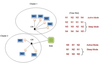
Low-Energy Adaptive Clustering Hierarchy (LEACH) is a clustering based protocol that uses a randomised rota-tion of local cluster base starota-tions. The nodes in LEACH are divided into clusters and each cluster consists of members called Cluster Members and a coordinator node called the Cluster Head, CH. The cluster heads are not selected in the static manner that leads to quick die of sensor nodes in the network. However, the randomised protocol has been used in order to balance the energy consumption among the nodes by distributing the CH’s role to the other nodes in the network. Furthermore, LEACH uses Time Division Multiple Access (TDMA) protocol in order to regulate the channel access within a cluster [1].
It is the responsibility of the CHs to assign TDMA slots to the cluster members. The peer to peer communi-cation between the CH and a member is done just during the time slot that assigned to that member, and the other members will be in their sleep state. Hence, it decreases the energy dissipation; see Figure 1. Moreover, LEACH uses the TDMA communication protocol to decrease the interference between the clusters.
Figure 1. LEACH protocol and TDMA schedules
more energy [2]. The CH aggregates/combines the col-lected data by the nodes to the smaller size and mean-ingful data, and then sends the aggregated data to the sink consuming less energy. LEACH tries to send the data over short distances and reduce number of the tran- smissions, where the energy consumptions depend on the distance and data size. As a result, the main problem with LEACH is the direct sending of CH to the sink, espe-cially when these CHs are located far away from the sink. However, allowing the multi-hop transmission to the sink through other CHs will solve this issue, where the CH just forwards the data to others until it reaches the sink and does not have to re-aggregate the data come from other CHs.
LEACH, compared to the direct communication and other minimum energy routing protocols, achieves a sig-nificant reduction in energy dissipation. Finally, the main properties (advantages and disadvantages) of LEACH include [1,2].
2.2. Advantages of LEACH
It limits most of the communication inside the clus-ters, and hence provides scalability in the network.
The CHs aggregates the data collected by the nodes and this leads to a limit on the traffic generated in the network. Hence, a large-scale network without traffic overload could be deployed and better energy efficie- ncy compared to the flat-topology could be achieved.
Single-hop routing from node to cluster head, hence saving energy.
Distributiveness, where it distributes the role of CH to the other nodes.
It increases network lifetime in three ways. Firstly, distributing the role of CH (consumes more energy than normal nodes) to the other nodes. Secondly, ag-gregating the data by the CHs. Finally, TDMA, which, assigned by the CH to its members, puts most of the sensor in sleep mode, especially in event-based ap-plications. Hence, it is able to increase the network lifetime and achieve a more than 7-fold reduction in energy dissipation compared to direct communication [1].
It does not require location information of the nodes to create the clusters. So, it is powerful and simple.
Finally, it is dynamic clustering and well-suited for applications where constant monitoring is needed and data collection occurs periodically to a centralised lo- cation.
2.3. Disadvantages of LEACH
It significantly relies on cluster heads and face ro-bustness issues such as failure of the cluster heads.
Additional overheads due to cluster head changes and calculations leading to energy inefficiency for dyna- mic clustering in large networks.
CHs are not uniformly distributed; CHs could be lo-cated at the edges of the cluster.
CH selection is random, which does not take into ac-count energy consumption.
Finally, it does not work well in the applications that cover a large area that requires multi-hop inter cluster communication.
2.4. Improvements of LEACH
Due to some drawbacks of LEACH, much research has been done to make this protocol perform better. Some of these pieces of research are: E-LEACH, TL-LEACH, M-LEACH, LEACH-C and V-LEACH [3].
2.4.1. E-LEACH
Energy-LEACH protocol improves the CH selection pro- cedure. Like LEACH, it divided into rounds, where in the first round all nodes have the same probability to be CH. However, after the first round the remaining energy of each node is different and the node with high residual energy will be chosen as CH rather than those with less energy [4].
2.4.2. TL-LEACH
in LEACH, the CH sends the data to the base station in one hop. However, in Two-Level LEACH, the CH col- lects data from the cluster members and relays the data to the base station through a CH that lies between the CH and the base station [5].
2.4.3. M-LEACH
As mentioned above, in LEACH, the CH sends the data to the base station in one hop.In Multi-hop-LEACH pro- tocol, the CH sends the data to the sink using the other CHs as relay stations [6]. In this protocol, the problem with CHs that are away from the base station, where they were consuming huge amounts of energy during data transmissions, has been solved.
2.4.4. V-LEACH
In the new Version of LEACH protocol, in addition to having a CH in the cluster, there is a vice-CH that takes the role of the CH when the CH dies [7]. When a CH dies, the cluster become useless, because the information collected by the node members will not reach the sink.
2.4.5. LEACH-C
LEACH has no knowledge about the CHs places. How- ever, Centralised LEACH protocol can produce better performance by distributing the cluster heads throughout the network. During the set-up phase, each node sends to the sink its remaining energy and location. The sink then runs a centralised cluster formation algorithm to deter- mine the clusters for that round. However, since this pro-
tocol requires location information for all sensors in the network (normally provided by GPS), it is not robust [8].
2.5. Directed Diffusion
Directed diffusion is data-centric routing protocol for collecting and publishing the information in WSNs. It has been developed to address the requirement of data flowing from the sink toward the sensors, i.e., when the sink requests particular information from these sensors [9]. Its main objective is extending the network life time by realising essential energy saving. In order to fulfil this objective, it has to keep the interactions among the nodes within a limited environment by message exchanging. Localised interaction that provides multi-path delivery is a unique feature of this protocol. This unique feature, with the ability of the nodes to respond to the queries of the sink, results in considerable energy savings [10].
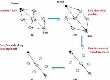
In order to construct the route between the sink (in- quirer) and the sensors that interest to the sink’s request, there are four stages; (A) interest propagation, (B) gradi- ent setup, (C) reinforcement, and (D) data delivery. Be- low is a detailed description for each stage:
1) Interest propagation: when a sink detects an event, it initiates the interest messages and floods them to all nodes in the network. These messages are exploratory messages indicating the nodes with matching data for the specific task. During this stage, the sink periodically broadcasts the interest message. Once the interest mes- sage is received, each sensor node saves it in an interest cache. After that, the nodes flood this message to the other nodes until the node that is interested in this inter- est message; see Figure 2(a).
2) Gradient setup: based on local rules, different tech- niques are used in gradient setup. For example, the nodes with highest remaining energy could be chosen when setting up the gradient. During the interest propagation through the network, the gradients from source back to sink will be setup. A node becomes a source node if its observation matches the interest message and sends its data through the gradient path back to the sink as shown in Figure 2(b).
Figure 2. Operation of the directed diffusion protocol.
4) Data delivery: after the reinforcement phase, as
shown in Figure 2(d), the route between the source and the sink has been constructed and the data is ready for transmission. As a result, we can say the Directed Diffu-sion is characterised by these following specifications [11,12]:
It requires neither a global node addressing mecha-nism nor a global network topology. Moreover, the routes are formed only when there is an interest. As a result, it achieves energy efficiency.
In order to satisfy the user’s requests, network routes are changed according to sensor reading changes.
The nodes that have matching information are only the nodes that involved in the information generation.
2.5.1. Advantages of Directed Diffusion
It is designed to retrieve data aggregates from a single node.
It mostly selects a specific route for the interest. Hence, it decreases the energy consumption in the network.
Data is named by attributed-value pairs.
It works well in multipurpose wireless sensor net-works and in sensor netnet-works that query, for example, “GIVE ME THE TEMPERATURE IN PARTICU-LAR AREA” or “WHO CAN SEE THE BLACK COW”.
2.5.2. Disadvantages of Directed Diffusion
It is, generally, based on a flat topology. Hence, scal-ability and congestion (especially in the nodes that near to the sink) problems exist.
An overhead problem occurs at the sensors during the matching process for data and queries.
Unlike other routing algorithms, in Directed Diffu-sion more than one sink can make queries and receive data at the same time; hence, simultaneous queries could be handled inside a single network.
In Directed Diffusion, the initial interest contains a low data rate. However, an important overhead is caused during flooding operation of interest propaga-tion phase.
The interests/queries are issued by the sink not by the sources, and only when there is a request. Moreover, all communication is neighbour-to-neighbour, which removes the need for addressing and permits each node to aggregate data. As a result, both points con-tribute to reduce energy consumption.
Due to the flooding required to propagate the interest on each node, it is not optimised for energy efficiency and need high amounts of memory to store interest gradients and received messages.
It mostly selects the shortest path between the source and the destination, which leads to quick death of
nodes on that path [12].
Finally, Directed Diffusion is a query-based protocol. It may be not work well in applications where con-tinuous data transfers are required (dynamic applica-tions); for instance, environmental monitoring appli-cations.
2.6 Gossiping Protocol
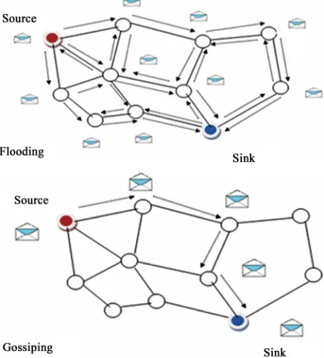
Gossiping is data-relay protocol, and, like Flooding pro-tocol, does not need routing tables and topology mainte-nance. It was produced as an enhancement for Flooding and to overcome the drawbacks of Flooding, i.e., implo-sion. In Flooding, a node broadcasts the data to the all of its neighbours even if the received node has just received the same data from another node. The broadcasting will continue until the data is received by the destination [11]. However, in Gossiping, a node randomly chooses one of its neighbours to forward the packet to, and once the se-lected neighbour node receives the packet, it chooses, in turn, another random neighbour and forwards the packet to them. This process will continue until the destination or number of hops has been exceeded. As a result, only the selected nodes/neighbours will forward the received packet to the sink. Unlike Flooding, Gossiping serves well at one-to-one communication scenarios but it does not at one-to-many. Packet forwarding mechanisms for both Flooding and Gossiping are shown in Figure 3 [13].
[image:5.595.57.288.454.709.2]The main objective of Gossiping was reducing the power consumption and keeping the routing system as
Figure 3. Forwarding mechanisms of both flooding and gossiping.
simple as possible. However, it suffers from the latency caused by the data propagation. The power consumed by Gossiping [14], is approximately equal to
O (KL)
K: Number of nodes that forward the packet.
L: Number of hops before the forwarding stops. The most considerable feature of Gossiping is the abil-ity of controlling the power consumption by selecting appropriate K and L.
2.6.1. Advantages of Gossiping
It is very simple and does not need any routing table and topology maintenance. So, it consumes little en-ergy.
It appeared as an enhancement to overcome the im-plosion that exists in Flooding.
In Gossiping, only the selected nodes contribute in forwarding the data to the sink.
It works well in applications that need one-to-one communication but it does not in one-to-many.
2.6.2. Disadvantages of Gossiping
The next hop neighbour is randomly chosen, which means it may include the source itself.
The packet will travel through these selected neigh- bours until it reaches the sink or number of hops ex-ceeds
It suffers from packet loss.
The remarkable disadvantage of Gossiping is suffer-ing from latency caused by data propagation.
2.6.3. Improvements in Gossiping
Finally, in order to enhance the Gossiping protocol, ma- ny protocols have been produced as an extension. For example FLOSSIPING, SGDF, LGOSSIPING and EL-GOSSIPING.
2.6.3.1. FLOSSIPING Protocol
It combines the approaches of both flooding and the gos-siping routing protocols. When a node has a packet to send, it decides a threshold and saves it in the packet header, then randomly selects a neighbour to send the packet to in Gossiping mode, while the other neighbour nodes listen to this packet and generate a random number. The neighbours whose generated random numbers are smaller than the threshold will broadcast the packet in Flooding mode. As a result, Flossiping improves the packet overhead in Flooding and the delay issue in the Gossiping [13].
2.6.3.2. SGDF Protocol
node generates a gradient (shows number of hops to the sink). In the second phase, in order to deliver the packet, SGDF uses single gossiping and directional flooding routing schemes. As a result in Figure 4, SGDF achieves high packet delivery ratio, low message complexity, and short packet delay [13].
2.6.3.3. LGOSSIPING Protocol [15]
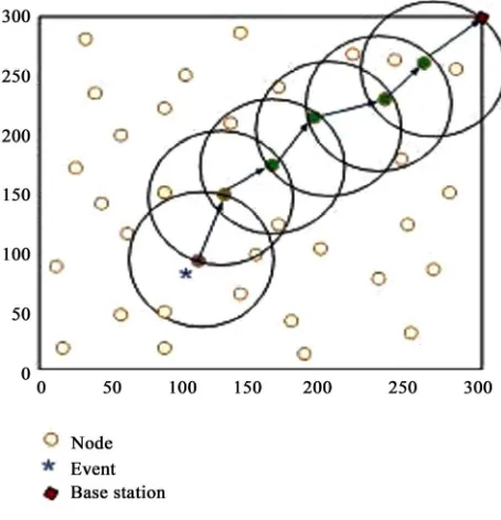
In Location based Gossiping protocol, when a node has an event to send, it randomly chooses a neighbour node in its transmission radius. Once the neighbour node re-ceives this event, it, in turn, randomly chooses another node within its transmission radius and sends it. This process will continue until the sink. As a result, the delay problem has been solved to some extent. Figure 5 shows the main objective of LGOSSIPING.
2.6.3.4 ELGOSSIPING Protocol [16]
[image:6.595.308.539.83.276.2]In ELGOSSIPINGprotocol, when a node detects an event and want to send, it selects a neighbour node within its transmission radius and the lowest distance to the base station/sink. Once the neighbour node receives the event, it, in turn, selects another neighbour node within its tran- smission radius and also the lowest distance to the sink. The event will travel in the same way until the sink. As a result, the problem of the latency and situation of non- reaching packets has been solved to some extent. See
Figure 6.
2.7. Energy Efficient Sensor Routing Protocol
Energy-Efficient Sensor Routing (EESR) is a flat routing algorithm [17] proposed especially to reduce the energy consumption and data latency, and to provide scalability in the WSN. Mainly, it consists of Gateway, Base Station, Manager Nodes, and Sensor Nodes [18]. Their duties are:
- Gateway: Deliver messages from Manager Nodes or
form other networks to the Base Station.
[image:6.595.308.535.307.543.2]Figure 4. Routing scenario in SGDF.
Figure 5. Schematic of data routing in LGOSSIPING.
Figure 6. Routing in ELGOSSIPING.
- Base Station: Has extra specifications compared to
normal sensor nodes. It sends and receives messages to/from the Gateway. Moreover, it sends queries and collect data to/from sensor nodes.
- Manager Nodes and Sensor Nodes: Collect data from
the environment and send it to each other in 1-Hop distance until the Base Station.
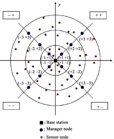
[image:6.595.58.289.543.719.2]position in the quadrant. Manager Nodes are located (predetermined) in the centre of each sector on the di-agonal line of the quadrant with 1-hop distance between each other. Finally, the other nodes are randomly distrib-uted in the application area; see Figure 7 [17].
As shown in Figure 7, each quadrant has three sectors because the Base Station can communicate with the fur-thest node in a minimum of 3-hops. Each sector has its own ID, gathered it from Base Station, determined by the quadrant name and the distance from the base station. For example, 1-hop distance sectors names are (+1 +1) sector, (+1 –1) sector, (–1 –1) sector, and (–1 +1) sector.
Each sensor node constructs its EESR table, as shown in Table 1, by broadcasting a “HELLO” message within 1-hop neighbour. The table contains distance from the base station, Quadrant Names, Sector ID and Manager Node Names.
2.7.1. The Algorithm
After the nodes are deployed, the Base Station sends the relative direction information and sector ID of each node, then each node constructs its EESR table. Once a node detects an event, in order to select the next node to de-liver the event, it investigates the sector ID of all neigh- bour nodes within 1-hop in its EESR table. The node selects its next node in one of these three procedures:
[image:7.595.306.539.111.279.2] If a Manager node is within 1-hop distance, it will be the next hop.
[image:7.595.59.283.436.709.2]Figure 7. Locations of the nodes based on 2-dimensional (x, y) Coordinates.
Table 1. Quadrant names, sector ID, and manager node names.
Distance from
the base station Quadrant name Sector ID Manager Node name (+ +) (+1+1)sector +1 +1M.N (+ –) (+1 –1)sector +1 –1M.N (– –) (–1 –1)sector –1 –1M.N 1 hop
(– +) (–1 +1)sector –1 +1M.N (+ +) (+2 +2)sector +2 +2M.N (+ –) (+2 –2)sector +2 –2M.N (– –) (–2 –2)sector –2 –2M.N 2 hop
(– +) (–2 +2)sector –2 +2M.N
(+ +) (+3 +3)sector +3 +3M.N (+ –) (+3 –3)sector +3 –3M.N (– –) (–3 –3)sector –3 –3M.N 3 hop
(– +) (–3 +3)sector –3 +3M.N
If there is no Manager node, it will check for a normal 1-hop distance node that exists on the same sector to be the next hop.
Otherwise it will look to another node that lies out of its sector but close to the Base Station to be the next hop. The nodes that lie on the same quadrant are the preferred ones
After selecting its next neighbour node, the first node will send the event only to this selected node. Once the selected node receives the event, it, in turn, repeats the same procedure to select its next 1-hop and send the event. This process will continue until the Base Station receives the event. However, if a Manager Node receives the event, the event will transmit from manager-manager until the Base Station [17].
2.7.2. Advantages of EESR
It divides the application area into sectors; hence, it is scalable.
It energy-efficient and achieves this feature in three ways: firstly, it sends the event to the just one node and does not flood it; secondly, Manager Nodes relay the data in a predefined shortest path; and finally, af-ter sending the first event, normal nodes will easily select the next node by using their EESR tables. As a result, it consumes little energy and prolongs the network life time.
It uses one-one communication. Moreover, after send- ing the first event, the next hop will be found easily. As a result, it is low latency.
In order not to send the data through a same route and exhaust energy of these nodes, sometimes, it chooses other routes to deliver the data.
2.7.3. Disadvantages of EESR
If a node located in the furthest sector detects an event and the next hop is located in the lower sector, the data will be lost in the case where the lower node’s energy has had finished.
If the normal nodes that are located in the furthest sec- tor detect an event and accidently every time their next hop is a Manager Node, the energy of these Ma- nager Nodes will exhaust earlier, because they will send the event manager-manager until the Base Station.
There is no balance in energy consumption, i.e., some nodes consume their energy before other nodes.
2.7.4. Improvement of EESR
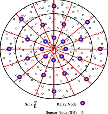
Due to these drawbacks, I proposed a new optimal rout-ing algorithm in EESR by creatrout-ing concentric sectors.
Our first Solution: is increasing number of the High- ways (diagonals) in each quadrant as shown in Figure 8. In this solution, the second and the third problems (men-tioned above in the disadvantages of EESR) have been solved. However, the first problem is the most important issue that needs to be solved.
Our second Solution: is fairly determining a number of relay nodes (Manager Nodes) in each secto regardless of the highways, as shown in Figure 8. In this solution, the first and the last problems have been solved [19].
The routing process of this enhancement protocol is as shown in the following flow chat in Figure 9.
3. Comparison of Explored Routing Protocols
[image:8.595.325.521.83.289.2]During this research, many differences have been ob- served, generally between flat and hierarchical routing protocols and, precisely, among these researched routing protocols. When compared to the other protocols, Gos- siping is very simple and does not need any routing table
Figure 9. Rely nodes in each sector.
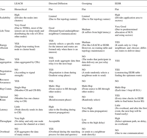
or topology management. It provides very high connec-tivity, where as soon as a node becomes aware of its neighbours it is able to send and forward packets. Gos-siping protocol is based on the flooding protocol. Instead of broadcasting each packet to all neighbours, the packet is sent randomly to a single neighbour, meaning only one copy of a packet is in transit at any one time. Having received the packet, the neighbour chooses another ran-dom node to send it to. However, this can include the node which sent the packet itself. This process continues until the packet reaches its destination or the maximum hop count of the packet is exceeded. As a result, com-pared to LEACH, Directed Diffusion nor EESR Proto-cols, Gossiping uses a medium amount of power and it appears to evaluate the improvements over Flooding, not over LEACH, Directed Diffusion and EESR. Gossiping, compared to other Protocols, suffers from quite high la-tency because of the data propagation through network (one to one communication) and the hop count could become quite large due to the random nature of the pro-tocol. As the number of nodes in a network increases, the number of paths that a packet can follow increases. On average, the number of hops taken to traverse the net-work increases. Hence, packets are dropped when the packets hop count reaches a maximum value. In larger networks it is more likely that a packet’s hop count will reach this value and so more packets are dropped. In smaller networks, roughly half of the packets sent are lost, and in larger networks the loss rate increases drasti- cally. As a result, the Gossiping protocol is the worst protocol in terms of loss of data packets. Hence, Gossip- ing is not Scalable like LEACH, Directed Diffusion and EESR. As a result, we summarised all that was men-tioned above in two tables; Table 2 [20], shows a general comparison of different routing approaches for flat and hierarchical sensor networks, and Table 3 shows how
[image:8.595.68.277.500.721.2]lat and hierarchical routing protocols.
[image:9.595.58.536.100.264.2]Hierarchical Routing
Table 2. General comparison between f
Flat Routing
Reservation-based scheduling Contention-based scheduling
Collisions avoided Collision overhead present
Reduced duty cycle due to periodic sleeping olling sleep time of nodes
neighbours
onisation
he network ransmission
n traffic patterns
ontrolled
Variable duty cycle by contr
Data aggregation by cluster-head Node on multi-hop path aggregates incoming data from Simple but non-optimal routing Routing can be made optimal but with an added complexity.
Requires global and local synchr Links formed on the fly without synchronisation
Overhead of cluster formation throughout t Routes formed only in regions that have data for t Lower latency as multiple hops network formed by
cluster—heads always available Energy dissipation is uniform
Latency in waking up intermediate nodes and setting up the multipath
Energy dissipation depends o
Energy dissipation cannot be c Energy dissipation adapts to traffic pattern
Fair channel allocation Fairness not guaranteed
Table 3. Comparison between LEACH, directed diffusion and gossiping routing protocols.
LEACH Directed Diffusion Gossiping EESR
Class Hierarchical Flat Flat Flat
Scalability es the nodes into Limited
lat topology nature)
Limited
lat topology nature) es application area to High
(Divid
clusters) (Due to f (Due to f
High (Divid sectors)
Life Time
d
, most of the Good
nd-based andneighbour- Medium
from high latency)
Very Good
etermined
Energy YES e-hop routing from
YES
y selects a specific route Medium
LEACH or EESR. d
YES
ds only to 1-hop s
differ-Data tion
YES
ggregated by CHs) node aggregate data then NO
nodes that participate in YES
Negotiation- NO
ording to signal
YES
tiation is done during de randomly selects a
YES
ructing EESR table
se
YES YES NO NO
Hop Comm. Single-Hop d CH-BS)
Hop
to BS through
i-Hop
S through Multi-Hop -hop till B.S.)
Optimal
ber has one chance
orcement phase) domly select) time checks its EESR
Latency directly sends its data
High
the flooding during Very High
propagation)
erhead, and after the first
Throughput
Very high
nd only one node Acceptable Low
o the high delay) t optimum path, no delay,
Overhead (CH aggregates the data of many nodes)
YES
(Overhead during the matching process for data and queries)
NO
(it sends to a neighbour node directly)
NO
(One to one communication) Very Goo
(Due to TDMA
sensors are in sleep mode and distributing the role of CH to other nodes)
(Dema
neighbour Communication) (It suffers
(Due to pred allocation of M.N. and using sectors)
efficient (Singl
node to cluster head)
(mostl
for the interest and routes are formed only when there is an interest)
YES
(Not like
However, no routing table an topology maintenance)
(It sen
neighbours and choose ent routes to deliver data)
aggrega (data a (each
relay it to the next hop)
(The
data delivery are just relay stations) NO based Recour (Acc strength) (Nego
Gradient setup phase)
(A no
neighbour node to send)
(const
finding the optimum route)
Awareness (Member-CH an Multi-(From source other nodes) YES Mult
(From source to B other nodes)
NO
(Each time 1
Route
NO (Mem relay to CH)
Little
(Reinf (Ran
YES (Every
table to find better Sector ID)
Little
(Node to CH)
(due to
interest propagation) (Due to data
(No ov
event, the next hop will be found easily)
High (No delay a
accesses the channel at a time)
NO
(Due t (Selec
[image:9.595.61.536.289.737.2]Continued
(Only when an event occurs
does the sensor detect it) user only when there is a request)
(only when an event occur the sensor detect it)
(Only when an event occur the sensor detect it) -based
Event-based Query-based
(The queries are issued by the Event-based Event-based
Applications t
occurs a node detect it)
ake e data at
d network initialisation
nitoring, i.e., ation Monitoring app.
(Dynamic app. -If an even
Multi-purposes Applications
(more than one sink can m queries and receiv the same time)
Application need
(one-to-one communication)
Monitoring app. (Dynamic app.)
App. Type Health monitoring (artificial Retina)
Environmental monitoring (PODS Hawaii)
Environmental monitoring or
during deployment phase an Environmental mo Agricultural applic
these resear rotocols (L Diffusion, G SR) fit und
ories and also compares these routing techniques
ac-in order to enhance the draw-ba
e be
. However, th
of many events to the main sta-tio
lay of delivering the packets to the Base St
d by a limited ca-pacity of batteries. Because of the power management
acti
dyn hese essential prope ad- ditional challenges to the communication protocols. In this article we studied the operation of routing protocols
umption and discussed impact
fac-uary 2000. doi:10.1109/HICSS.2000.926982
ched routing ossiping and EE
p EACH, Dire
er different cate-cted
g
cording to many metrics.
With some changes in Gossiping Protocol, we can de-crease the energy consumption and also inde-crease Net-work lifetime. Therefore,
cks of Gossiping Protocol, many new protocols have been proposed as an extension for Gossiping: for exam-ple, Flossiping, SGDF, LGossiping and ELGossiping:
Flossiping combines the two protocols of Flooding
and Gossiping. In this protocol, the overheads that exist in the flooding and the delays that exist in gossiping hav
en improved. However, the power consumption and packet delay time in this protocol are the same as the flooding and the gossiping routing protocols.
(SGDF) Single Gossiping with Directional Flooding routing protocol achieves high packet delivery ratio, low message complexity, and short packet delay
e ill side effect of this protocol is that the amount of packets becomes larger during packet delivery because of the directional flooding.
LGossiping Although in this protocol the delay
prob-lem has been solved to some extent, there is still the problem of non-reaching
n. Moreover, this protocol uses GPS to determine the location of each node. Hence, additional hardware means extra money.
ELGossiping is proposed to improve the LGossiping
protocol. It has improved the network life time and has solved the de
ation and non-reaching packets to some extent, but not completely. In this protocol, two important metrics have been exploited: energy and distance to the base station; and in this way, when a node detects an event within its transmission range, it sends the data to a neighbour node that has lower distance to the sink.
4. Conclusion
Wireless Sensor Networks are powere
vities of these sensor nod amically changes. T
es, the network topology rties pose
with safe energy cons
tors in energy optimisation. With a little care in Gossip-ing protocol we can find that by makGossip-ing some changes in choosing of the next hop, the network lifetime can be increased.
REFERENCES
[1] W. Heinzelman, A. Chandrakasan and H. Balakrishnan, “Energy-Efficient Communication Protocol for Wireless Microsensor Networks,” Proceedings of the 33rd Annual International Conference on System Sciences, Vol. 2, Maui, 4-7 Jan
[2] J. Zheng and A. Jamalipour, “Wireless Sensor Networks:
A Networking ey & Sons, Hobo-
ken, 2009.
Perspective,” John Wil
[3] W. Heinzelman, A. Chandrakasan and H. Balakrishnan, “An Application-Specific Protocol Architecture for Wire- less Microsensor Networks,” IEEE Transactions on Wire- less Communications, Vol. 1, No. 4, 2002, pp. 660-670. doi:10.1109/TWC.2002.804190
[4] X. N. Fan and Y. L. Song, “Improvement on LEACH Protocol of Wireless Sensor Network,” International Con- ference on Sensor Technologies and Application, Valen-
yseh and W. Mar-
, Hoboken, 2007. cia, 14-20 October 2007, pp. 260-264.
[5] V. Loscrì, G. Morabito and S. Marano, “A Two-Levels Hierarchy for Low-Energy Adaptive Clustering Hierar- chy,” IEEE 62nd Vehicular Technology Conference, 25-28 September 2005, pp. 1809-1813
[6] Hang Zhou, Zhe Jiang and Mo Xiaoyan, “Study and De-sign on Cluster Routing Protocols of Wireless Sensor Networks”, 2006.
[7] M. B. Young, A. Al-zou'bi, Y. Khama
dini, “Improvement on LEACH Protocol of Wireless Sen- sor Network (VLEACH),” International Journal of Digi-tal Content Technology and Its Applications, Vol. 3, No. 2, 2009, pp. 132-136.
[9] C. Intanagonwiwat, R. Govindan and D. Estrin, “Directed Diffusion: A Scalable and Robust Communication Para- digm for Sensor Networks,” Proceedings of the 6th An- nual International Conference on Mobile Computing and Networking, Boston, 6-11 August 2000, pp. 56-67.
of 12th Interna-
[10] Y. H. Lee, K. O. Lee, H. J. Lee and A. Kusdaryono, “CBERP: Cluster Based Energy Efficient Routing Protocol for Wireless Sensor Network,” Proceedings
tional Conference on Networking, VLSI and Signal Proc- essing, Cambridge, 20-22 February 2010, pp. 24- 28. [11] I. Akyildiz and M. Canvuran, “Wireless Sensor Networks,”
Wiley, London, 2010. doi:10.1002/9780470515181 [12] M. Eroglu, “New Stack Architecture for Sensor Net-
works,” Master’s Thesis, Middle East Technical Univer- sity, Ankara, 2006.
[13] W. Yen, C.-W. Chen and C.-H. Yang, “Single Gossiping with Directional Flooding Routing Protocol in Wireless Sensor Networks,” 3rd IEEE Conference on Industrial Electronics and Applications, Singapore, 3-5 June 2008, pp. 1604-1609. doi:10.1109/ICIEA.2008.4582790 [14] Y. C. Zhang and L. Cheng, “Flossiping: A New Routing
Protocol for Wireless Sensor Networks,” IEEE Interna- tional Conference on Networking, Sensing and Control
Mobile
, Taipei, 21-23 March 2004, Vol. 2, pp. 1218-1223.
[15] S. Kheiri, G. Ghaznavi, M. Rafiee and B. Seyfe “An Im- proved Gossiping Data Distribution Technique with Em- phasis on Reliability and Resource Constraints,” IEEE
International Conference on Communications and Computing, Yunnan, 6-8 January 2009, pp. 247-252. doi:10.1109/CMC.2009.349
[16] A. Norouzi, M. Dabbaghian, A. Hatamizadeh and B. Berk Ustundag, “An Improved ELGossiping Data Distribution Technique with Emphasis on Reliability and Resou Constraints in Wireless Sens
rce or Network,” IEEE Interna-
. 147-152.
tional Conference on Electronic Computer Technology, Kuala Lumpur, 7-10 May 2010, pp. 179-183.
[17] H. Oh and K. Chae, “An Energy-Efficient Sensor Routing with Low Latency, Scalabilit in Wireless Sensor Networks,”
IEEE International Conference on Multimedia and Ubiq- uitous Engineering, Seoul, 26-28 April 2007, pp
[18] H. Oh, H. Bahn and K. Chae, “An Energy-Efficient Sen-sor Routing Scheme for Home Automation Networks,”
IEEE Transactions on Consumer Electronics, Vol. 51, No. 3, 2005, pp. 836-839. doi:10.1109/TCE.2005.1510492 [19] M. H. Khodashahi, A. Norouzi, F. Amiri and M. Dabbag-
hian, “A Novel Optimal Routing Algorithm by Creating Concentrically Sectors in Wireless Sensor Networks,” 8th IEEE Annual Communication Networks and Services Re-
109/MWC.2004.1368893
search Conference, Montreal, 11-14 May 2010, pp. 168- 173.