High Strain Rate Superplasticity of Mg Based Composites
Fabricated by Friction Stir Processing
C. J. Lee and J. C. Huang
*Institute of Materials Science and Engineering, Center for Nanoscience and Nanotechnology, National Sun Yat-Sen University, Kaohisung, Taiwan 804, R. O. China
The nano-sized SiO2particles were added into the AZ61 Mg alloys via friction stir processing (FSP) to a volume fraction of 5–10%. After four FSP passes, the 10% composites had uniform dispersion of particles and grain size of 0.8mm. This composite exhibited high strain rate superplasticity, with a maximum ductility of 470% at1102s1and 300C or 454% at3101s1and 400C while maintaining fine grains
less than 2mmin size. [doi:10.2320/matertrans.47.2773]
(Received May 22, 2006; Accepted September 5, 2006; Published November 15, 2006)
Keywords: Friction stir processing, magnesium composite, high strain rate superplasticity
1. Introduction
Mg based alloys are the lightest structural materials, highly attractive in terms of weight and energy saving. However, the intrinsically poorer ductility of Mg alloys would limit their applications. A number of thermomechanical processing (TMP) methods, such as rolling, extrusion, equal channel angular pressing (ECAP) have demonstrated the feasibility to remarkably improve the ductility and formability.
Magnesium matrix composites, with the addition of ceramic reinforcements could further improve the strength, wear and creep resistance. But they are also inherited with the poor ductility, toughness and workability of Mg materials. High strain rate superplasticity (HSRSP), with a total
elon-gation >200% at a high strain rate greater than102s1, in
these composites may provide a chance to upgrade the workability and to form complicated shape for industrial applications.
The HSRSP behaviors observed in the Al based compo-sites usually occur at the partial melting temperatures with the help from a controlled amount of the liquid phase between the matrix and reinforcements to accommodate the stress concentration during deformation, as found in, for
example, the Al-Cu-Mg/Si3N4 composites.1) However, the
role of the liquid phase did not seem to be required in the Mg based composites due to the more rapid diffusion ability of
Mg atoms.2)The related HSRSP behaviors of the Mg based
composites3–6)are listed in Table 1. The reinforcement sizes
are all in the micron range. These Mg based composites have all been subjected to secondary TMP to uniformly disperse the reinforcements and to refine the grain size.
Friction stir processing (FSP) is an extension of friction stir welding (FSW) originally developed by The Welding
Institute of UK in 1991.7) Mishra et al. first applied this
process to achieve good superplasticity in the 7075 Al
alloys.8)After this, the HSRSP and low temperature
super-plasticity (LTSP) performance in the related Al alloys9–15)
also could be achieved by FSP thermomechanical treatment. Moreover, Mishra showed the possibility to fabricate surface
composites in 5083 Al.16)Follow-up studies have extended
the FSP technique to fabricate many fine grained alloys,17)
composites,18)and intermetallic compounds.19)The sizes of
the inserted reinforcements have been varied from micron or submicron to the nano scales. FSP seems to be an effective
tool to disperse the nano fillers in the matrix.18)In this paper,
we report the results of HSRSP in the AZ61 Mg based
composites, with nano-sized SiO2particles, prepared by FSP.
2. Experimental Methods
The AZ61A billets used in this study have a chemical composition in mass percent of Mg-6.02%Al-1.01%Zn-0.30%Mn. This alloy is a solution hardened alloy with minimal precipitation. The billet possessed nearly equiaxed
grains around 75mm (based on the linear line intercept
method from three cross-sectional planes). The billet was cut as rectangular samples 60 mm in width, 130 mm in length and
10 mm in thickness. The amorphous SiO2 nano particles
applied are nearly equiaxed in shape and have an average
diameter hdi 20nm and purity 99:9%, and density of
2.65 Mg/m3.
The simplified FSP machine used in this experiment was a modified form of a horizontal-type milling machine, with a 5 HP spindle. The fixed pin tool was 6 mm in diameter and
6 mm in length. The shoulder diameter was 18 mm, and a 2
tilt angle of the fixed pin tool was adopted. The pitch distance was 1 mm. The advancing speed of the rotating pin was kept constant in this study to be 45 mm/min, with a fixed pin
rotation of the 800 rpm. To insert the nano SiO2particles, one
or two deep and shallow grooves6mm depth and 1.25 mm
wide were cut (termed as the 1D or 2D specimens), in which
the nano SiO2 particles to the desired amount were filled
before FSP. The volume fraction of the SiO2 nanoparticles
inserted in the 1D and 2D specimens within the stirred zone is estimated to be around 5 and 10 vol%, respectively. The groove(s) were aligned with the central line of the rotating pin. The detailed description of fabricating Mg based
composites has been presented in our previous paper.18)
The samples with SiO2 particles of one or two deep
grooves and four FSP passes (4P) were machined into tensile specimen, as shown in Fig. 1, with the gage length centered in the central region of the stirring zone. The tensile *Corresponding author, E-mail: [email protected]
specimens have a gage length 3 mm and width 2 mm, and are
ground and polished to a thickness of 1:2mm. Constant
crosshead speed tensile tests were conducted using an universal testing machine equipped with a three-zone
furnace. The temperature was controlled with 2C. The
AZ61 alloy processed by FSP for four passes without any
SiO2 filler was also conducted the same tensile tests for
comparison. The microstructure of FSP specimens was examined by scanning and transmission electron microscopy (SEM and TEM).
3. Results and Discussions
3.1 Microstructure of Mg based alloys and composites
According our previous results,18)the SiO
2particles in the
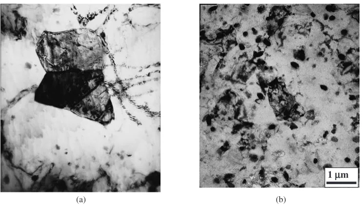
groove(s) could be uniformly dispersed in the stirring zone after four FSP passes. In the stirred zone, the grains of Mg based composites are fine and equiaxed, as shown in Fig. 2. The average grain size of 1D4P and 2D4P samples was close
to 1.8mmand 0.8mm, respectively. The same FSP parameters
(800 rpm and 45 mm/min) were also applied to the AZ61
alloys without SiO2, and the grain size yielded was 7–8mm,
as shown in Fig. 3. It is apparent that the nano-sized particles in the groove(s) played a key role in restricting the rapid grain growth during FSP.
In terms of the critical microstructure parameter of
L¼ ðhdi=2Þð2=3VfÞ1=220)wherehdi is the average particle
diameter and Vf is the volume fraction, it is reasonable that
the 1D4P grain size is higher than the 2D4P one due to the lower nano filler volume fraction. Theoretically, if all of the
20 nm SiO2 nano particles are completely and uniformly
dispersed, the theoretically estimated grain size should vary
within 0.1–0.2mm. Nevertheless, the average SiO2cluster for
1D4P and 2D4P samples is 190 and 150 nm, respectively. Due to a certain level of local clustering, the average
Materials Process Particle size,
D/mm
Temp, T/C
Strain rate, _
"
"/s1
Elongation,
% m value
Ref.
Mg-A1/Mg2S/28p Rapidly solidification +Extrusion 0.7 515 1101 370 0.5 3)
Mg-Zn/Mg2S/28p Rapidly solidification + 0.8 440 1101 290 0.5 3)
Extrusion
ZK60/SiC/17p PM + Extrusion 2 450 1101 360 0.5 4)
Mg-5Zn/TiC/20p Vortex casting + 2–5 470 6:7102 340 0.33 5)
Extrusion + rolling
Mg-5Al/AlN/15p Vortex casting + 0.72 450 5101 200 0.4 6)
Extrusion + rolling
Fig. 1 The sampled tensile specimen from the FSP stir zone with the tensile loading direction perpendicular to the FSP travel direction.
(a) (b)
1 µm
[image:2.595.53.549.85.227.2] [image:2.595.48.287.110.355.2] [image:2.595.113.484.558.769.2]resulting grain in the FSP stirred zone could only be refined to
0.5–2mm.
The grain size variation upon static annealing at 350C for
the AZ61 alloy and composites are shown in Fig. 4. The grains of the 1D4P and 2D4P composites could still be
maintained within 1–3mmeven after 10 h static annealing. In
comparison, the grains of the FSP AZ61 alloy grew rapidly
from 7 to 44mmafter 5 h annealing. It is apparent that the
nano SiO2 did play an effective role in controlling the grain
growth during FSP and subsequent static annealing or superplastic deformation at elevated temperatures.
3.2 Superplasticity behavior
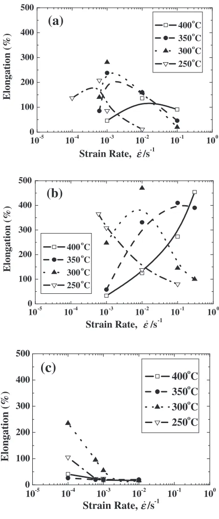
Systematic tensile tests were performed on the FSP 1D4P and 2D4P Mg based alloys and composites. Figure 5 shows the variation of tensile elongation as a function of strain rate
at 250–400C. It can be seen that the optimum strain rate for
superplasticity performance increased with increasing load-ing temperature. For example, the optimum strain rate at
250C for the 2D4P samples with an elongation of 370% is in
the range of104–103s1; and the optimum strain rate at
300 and 400C with an elongation of 470 and 454% could be
raised to1102and3101, respectively, exceeding the
criteria for HSRSP. In comparison, the highest superplastic elongations and the optimum strain rates of the 1D4P samples were all inferior to those of the 2D4P counterparts.
As for AZ61 alloys modified by FSP, it did not perform the same HSRSP behavior at the higher temperatures, such as
350 or 400C; nevertheless, the elongation could reach 235%
at 300C and1104s1, as shown in Fig. 5. These results
indicate that the current lower FSP travel speed of 45 mm/ min coupled with the medium pin rotation of 800 rpm would
result in relatively coarser grain sizes of 7–8mm, unfavorable
for HSRSP deformation. Meanwhile, the rapid grain growth
20 µm
Fig. 3 Optical micrograph of the AZ61 alloy processed by FSP for four passes.
0 8
0.1 1 10 100
Grain Size,
d
/
µ
m
Annealing Time,
t
/h
AZ61 alloy, 4P 1D4P2D4P
2 4 6 10
Fig. 4 Variation of grain sizes of the FSP AZ61 alloy and composites at 350C during static annealing.
10-5 10-4 10-3 10-2 10-1 100 0
100 200 300 400 500
(a)
Elongation (%)
Strain Rate, /s-1
400oC 350oC 300oC 250oC
10-5 10-4 10-3 10-2 10-1 100 0
100 200 300 400 500
(b)
Elongation (%)
Strain Rate, ε. /s-1
400oC 350oC 300oC 250oC
10-5 10-4 10-3 10-2 10-1 100 0
100 200 300 400 500
Elongation (%)
Strain Rate,
./s
-1400
oC
350
oC
300
oC
250
oC
(c)
ε.
ε
[image:3.595.315.539.71.601.2] [image:3.595.48.289.72.256.2] [image:3.595.58.283.302.476.2]of the unreinforced AZ61 alloy at elevated temperatures to
30–50mm would further reduce the possibility for HSRSP.
Only at relatively lower temperature such as 300C or below,
when rapid grain growth is unlikely to occur, superplasltic behavior can be retained.
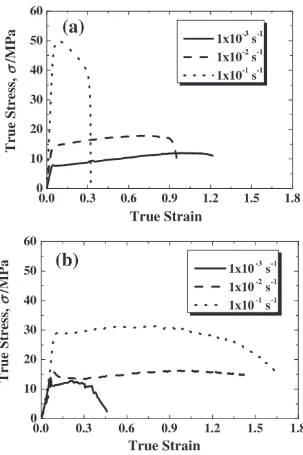
The representative stress-strain curves of the FSP
compo-sites tested at 350C are shown in Fig. 6. The flow stresses of
the 2D4P specimens at 350C did not exhibit strain
harden-ing, maintaining relatively stable flow stress of 15 and
30 MPa at 1102 and 1101. In contrast, the 1D4P
samples showed slight strain hardening, especially in range
of1103–1102s1. The flow stress levels of the 2D4P
specimen are typically lower than those of the 1D4P one at the same rate, implying the more smooth operation of grain boundary sliding and thus the lower flow stress.
Figure 7 shows the 2D4P specimens deformed at 1
102s1and3101s1. The 2D4P specimens deformed at
3101s1 and 350–400C show the neck-free gauge
section characteristic of superplastic flow. But the specimens
show a certain level of local necking at 1102s1 and
400C. It might be a result of cavitation at high temperatures
and lower strain rates with enough time and energy to make
vacancy diffusion for cavity nucleation.21)
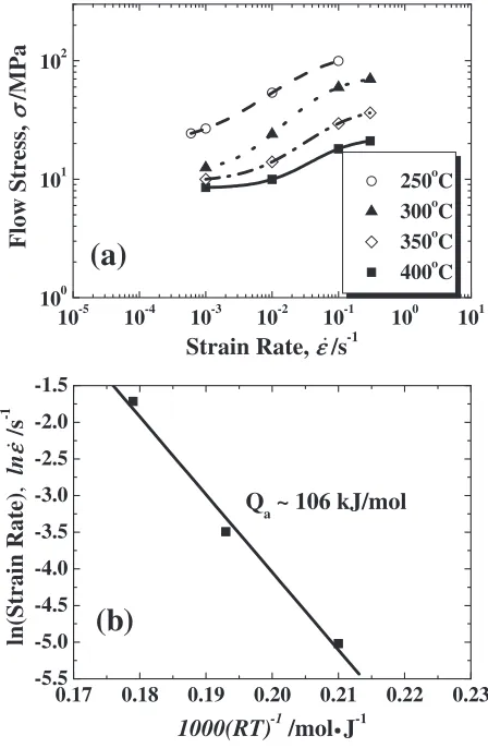
The flow stresses at a true strain of 0.3 of the 2D4P
composites loaded at 250–400C as a function of strain rate
are plotted in Fig. 8(a). The apparent m-value was estimated about 0.3–0.4 from the data in Fig. 8(a). With the consid-eration of the threshold stress, the true strain rate sensitivity
was calculated to be around 0.4–0.5, suggesting that the grain boundary sliding might be the dominant deformation
mech-anism. The apparent activation energyQa can be evaluated
according to the equation
Qa¼ R@ðln _""Þ
@ð1=TÞ
¼constant
; ð1Þ
where ""_, R andT are stain rate, gas constant and absolute
temperature, respectively. Taking ¼20MPa, Qa was
estimated from the slope of the plot of ln _"" against 1000/
RT, as shown in Fig. 8(b). The apparent activation energy
Qa over 250–400C is 106 kJ/mol, which is between the
activation energy for boundary self-diffusion of the Mg atoms (92 kJ/mol) and that for lattic self-diffusion of the Mg
atoms (135 kJ/mol).22)It is suggested that the
accommoda-tion mechanism may be dislocaaccommoda-tion slip plus climb, the latter
controlled by grain boundary diffusion. Watanabeet al.2)and
Mabuchiet al.3)have also reported the same deformation and
accommodation mechanism in the Mg based composites made by other processing routes.
It is known that grain size strongly affects the optimum
superplastic strain rate by the relation below:2)
_ " "¼A
T b d
p
E
n
D; ð2Þ
0.0 0.3 0.6 0.9 1.2 1.5 1.8
0 10 20 30 40 50 60
(a)
True Stress,
σ
/MPa
True Strain
1x10⁻³ s-1 1x10⁻² s-1 1x10⁻¹ s-1
0.0 0.3 0.6 0.9 1.2 1.5 1.8
0 10 20 30 40 50 60
(b)
True Stress,
σ
/MPa
True Strain
1x10⁻³ s-1 1x10⁻² s-1 1x10⁻¹ s-1
Fig. 6 True stress and strain curves for (a) 1D4P and (b) 2D4P specimens at 350C.
(a) 1x10⁻² s-1
(b) 3x10⁻¹ s-1
Undeformed
250oC, 135%
300oC, 470%
350oC, 331%
400oC, 125%
300oC, 100%
350oC, 391%
400oC, 454%
[image:4.595.59.279.71.401.2] [image:4.595.313.535.71.433.2]where A is a materials constant,the flow stress, E the elastic modulus, b the Burgers vector, D the diffusion coefficient, p
the grain size exponent, and n the stress exponent (¼1=m).
The 1D4P and 2D4P composites possessed the average grain
size around 2 and 0.8mm, respectively. The grain size
difference leads to the different optimal superplastic strain. Meanwhile, at the same strain rate, the 2D4P composites show the lower flow stresses and more smooth operation of grain boundary sliding, following the trend predicted by eq. (2).
3.3 Topography of deformed specimens
Figure 9 shows the surface topography of the 2D4P
specimen deformed at 350C and 1101s1 to a true
strain of 1.37. It reveals the evidence of grain boundary sliding. The grain size can be seen to be maintained in the
range of 1–2mm. The inserted nano particles have played an
effective role in restraining grains growth not only during FSP but also during the subsequent static annealing and superplastic deformation at elevated temperatures.
The fracture surface of the 2D4P specimen deformed at
350C and 1101s1 to failure, showing the HSRSP
elongation of 410%, is depicted in Fig. 10. The fracture surface of the HSRSP Al based composites often exhibit some long filaments after high strain rate deformation due to
the partial melting at grain or interface boundaries.23)Such a
phenomenon is not as apparent in the current Mg based
composites; but there are scratch-like marks on some exposed grain boundaries and occasional short grass-like appearance. The role of partial melting does not seem to be pronounced in the current Mg composites.
4. Conclusions
The four-pass FSP is demonstrated to fabricate an AZ61
Mg based composites with up to 10% of nano SiO2particles
measuring 20 nm. The nano particles can be reasonably uniformly dispersed, and restrict grain growth during FSP and subsequent static annealing or superplastic loading at
250–400C, limiting the grain size within 0.8–2.0mm.
Satisfactory high strain rate superplasticity over 450% elongations can be achieved in the 2D4P composite as
loaded at 300–400C and 102–101s1. The strain rate
sensitivity (0:5) and the activation energy (106kJ/mol),
coupled with the surface topography evidence, suggest that the dominant deformation mechanism is grain boundary sliding accommodated by dislocation slip plus climb, and the latter is controlled by grain boundary diffusion.
10-5 10-4 10-3 10-2 10-1 100 101 100
101 102
250oC 300oC 350oC 400oC
Flow Stress,
σ
/MPa
Strain Rate,
ε./s
-1(a)
0.17 0.18 0.19 0.20 0.21 0.22 0.23 -5.5
-5.0 -4.5 -4.0 -3.5 -3.0 -2.5 -2.0 -1.5
ln(Strain Rate)
,
ln
ε
.
/s
-1
1000(RT)
-1/mol J
-1Q
a~ 106 kJ/mol
(b)
Fig. 8 The analyses on the 2D4P composites samples for (a) flow stress against strain rate cures and (b) apparent activation energy.
1 µm
Fig. 9 SEM micrograph showing the surface topography of the 2D4P specimen deformed at 350C and1101s1to"¼1:37.
[image:5.595.57.281.72.415.2]1 µm
[image:5.595.312.542.72.243.2] [image:5.595.312.540.308.485.2]Acknowledgement
The authors are gratefully acknowledge the sponsorship by National Science Council of Taiwan, ROC, under the project no. NSC 93-2216-E-110-021.
REFERENCES
1) M. Mabuchi, K. Higashi and T. G. Langdon: Acta Metal. Mater.42
(1994) 1739–1745.
2) H. Watanabe, T. Mukai, M. Mabuchi and K. Higashi: Acta Mater.49
(2001) 2027–2037.
3) M. Mabuchi and K. Higashi: Philo. Mag. A74(1996) 887–905. 4) T. G. Nieh and J. Wadsworth: Scripta Metal. Mater.32(1995) 1133–
1137.
5) S. W. Lim, T. Imai and Y. Nishida: Scripta Metal. Mater.32(1995) 1713–1717.
6) T. Imai, S. W. Lim, D. Jiang and Y. Nishida: Scripta Mater.36(1997) 611–615.
7) W. M. Thomas, E. D. Nicholas, J. C. Needham, M. G. Church, P. Templesmith and C. J. Dawes: Intl Patent No. PCT/GB92/02203. 8) R. S. Mishra, M. W. Mahoney, S. X. Mcfadden, N. A. Mara and
A. K. Mukherjee: Scripta Mater.42(2000) 163–168.
10) Z. Y. Ma, R. S. Mishra, M. W. Mahoney and R. Grimes: Mater. Sci. Eng. A351(2003) 148–153.
11) H. G. Salem, A. P. Reynolds and J. S. Lyons: Scripta Mater.46(2002) 337–342.
12) Z. Y. Ma, R. S. Mishra and M. W. Mahoney: Acta Mater.50(2002) 4419–4430.
13) Z. Y. Ma, R. S. Mishra and M. W. Mahoney: Scripta Mater.50(2004) 931–935.
14) Z. Y. Ma and R. S. Mishra: Scripta Mater.53(2005) 75–80. 15) I. Charit and R. S. Mishra: Acta Mater.53(2005) 4211–4223. 16) R. S. Mishra, Z. Y. Ma and I. Charit: Mater. Sci. Eng. A341(2003)
307–310.
17) C. I. Chang, C. J. Lee and J. C. Huang: Scripta Mater.51(2004) 509– 514.
18) C. J. Lee, J. C. Huang and P. J. Hsieh: Scripta Mater.54(2006) 1415– 1420.
19) C. H. Chuang, J. C. Huang and P. J. Hsieh: Scripta Mater.53(2005) 1455–1460.
20) A. J. Ardell: Metall. Mater. Trans. A16(1985) 2131–2165. 21) C. J. Lee and J. C. Huang: Acta Mater.52(2004) 3111–3122. 22) H. J. Frost and M. F. Ashby: Deformation Mechansim Maps (Pergamon
Press, Oxford, 1982) p. 44.