Dissolution Behavior of Solid 5CaO
SiO
2P
2O
5in CaO-SiO
2-FeO
xSlag
Xiao Yang
*1, Hiroyuki Matsuura and Fumitaka Tsukihashi
*2Department of Advanced Materials Science, Graduate School of Frontier Sciences, The University of Tokyo, Kashiwa 277-8561, Japan
In order to clarify the dissolution behavior of solid P2O5rich phase in slag, the solid phosphate compound silicocarnotite 5CaOSiO2P2O5
being the representative of P2O5rich phase was dipped into the molten CaO-SiO2-FeOxslag at 1573 and 1673 K. Since the initial slag was free
of P2O5, the increase of P2O5 content in the slag is the indication of the dissolution behavior of solid 5CaOSiO2P2O5. Therefore, the
concentration profile of P2O5across the interface between solid 5CaOSiO2P2O5and slag was analyzed to evaluate the dissolution behavior.
The results show that the dissolution of solid 5CaOSiO2P2O5into slag can be divided into the following stages: interaction of solid phase
with slag, disintegration of solid phase, reaction between disintegrated solid phase and surrounding slag, and diffusion of CaO and P2O5from
solid sample to slag. The diffusivity of P2O5in the liquid slag was calculated. It was found that higher temperature is favored for the diffusion in
some cases, whereas larger CaO/SiO2ratio of the slag restrains the diffusion. [doi:10.2320/matertrans.M-M2010810]
(Received September 2, 2009; Accepted March 6, 2010; Published April 28, 2010)
Keywords: steelmaking, multi phase flux, dephosphorization, phosphorus oxide rich phase, dissolution, diffusivity
1. Introduction
The hot metal dephosphorization process has been uniquely developed to meet the increasing demand for low phosphorus steel production in Japan. The dephosphorizing reagent is usually composed of lime, iron ore and some other additives. The generated CaO-SiO2-FeOx-P2O5 based slag
after dephosphorization contains considerable amount of solid CaO, which causes problems such as increase of slag volume and difficulty of slag recycling. Though fluorspar (CaF2) had been used as an additive to enhance CaO
dissolution into liquid slag and improve fluidity, the use of CaF2 is strictly restricted at present owing to its toxic
property to human society. Consequently, the hot metal dephosphorization slag is a multi phase flux with solid and liquid phases coexisting. Reduction of the CaO consumption and the slag emission is the existing problem that the steelmakers confront. Since the slag contains both liquid and solid phases, it is considered that the problem can be solved by means of improving the transfer of phosphorus from liquid phase into solid phase in the slag to promote the utilization efficiency of solid CaO.
A lot of researches1–11) had been devoted to clarify the microscopic reaction mechanisms in the CaO based multi phase flux as the fundamental study to develop new refining technology. Since many researchers5–12) had confirmed the
existence of P2O5 in 2CaOSiO2 phase as 2CaOSiO2
-3CaOP2O5 solid solution or compound in steelmaking slag,
it is considered by the researchers that the precipitation of 2CaOSiO2 phase in the CaO based multi phase flux is the
necessary condition for the formation of solid P2O5 rich
phase. Following this idea, the present authors investigated the reaction behavior of P2O5at the interface between solid
2CaOSiO2 and CaO-SiO2-FeOx-P2O5 slag.13,14) It was
observed that the P2O5 condensed phases are formed at the
2CaOSiO2/slag interface in less than 1 s. Moreover, it was
also aware that the solid P2O5 condensed phase is possible
to re-dissolve into the slag after its formation, dependent on the slag composition and reaction temperature. Therefore, promotion of the formation at the same time restraint in the dissolution of the solid P2O5 rich phase in the multi phase
flux should be the guiding idea to innovate the present refining technologies. However, it is firstly needed to understand the dissolution behavior of the solid P2O5 rich
phase in the slag.
Inoueet al.15)studied the equilibrium between 2CaOSiO
2
-3CaOP2O5 solid solution and molten CaO-SiO2-FeOx slag
to measure the partition ratio of phosphorus. Utagawaet al.16)
dipped the rod of 2CaOSiO2-3CaOP2O5solid solution into
the CaO-SiO2-Fe2O3 slag and observed that the transfer of
P2O5 from solid solution to liquid slag was not fast. These
studies proved the occurrence of dissolution of solid P2O5
rich phase in slag. However, the detailed understanding about the dissolution process and mechanism is still unavailable.
The present study has been conducted to extend the understanding of the microscopic reaction mechanism in the multi phase flux by focusing on the dissolution behavior of the solid P2O5 rich phases in liquid slag. Silicocarnotite,
5CaOSiO2P2O5, which has the largest P2O5 concentration
among the P2O5 rich phases and is stable at hot metal
dephosphorization temperatures, was employed as the rep-resentative in the present work for the sake of an easier evaluation on the transfer behaviors of P2O5 in liquid slag.
5CaOSiO2P2O5 was dipped into CaO-SiO2-FeOx slag and
the interface between solid 5CaOSiO2P2O5and liquid slag
was observed. The concentration profile of P2O5 across the
interface was analyzed to evaluate the dissolution behavior. The influence of reaction temperature and slag composition on the dissolution behavior was also discussed.
2. Experimental
The CaO-SiO2-FeOxslag was prepared by mixing
synthe-sized CaO, FeOx, and reagent grade SiO2. Powder of CaO
was obtained by the calcination of reagent grade CaCO3for
*1Graduate Student, The University of Tokyo
*2Corresponding author, E-mail: [email protected]
(CO/CO2 = 1) for 24 h. The CaO-SiO2-FeOxslags with two
CaO/SiO2molar ratios and the same FeOxcontent were used
as listed in Table 1 where iron oxide is represented by FeO. The compositions are also plotted on the phase diagram for the CaO-SiO2-FeOx ternary system in Fig. 1 in which the
solid curves indicate the liquidus for the CaO-SiO2-FeO
system equilibrated with iron at 1573 and 1673 K.
The solid 5CaOSiO2P2O5was prepared by the following
procedure. Firstly, the mixture of CaO obtained by calcina-tion of CaCO3 and reagent grade SiO2 on molar ratio
of 2 : 1 was sintered in a platinum crucible at 1773 K for 24 h in air to synthesize 2CaOSiO2. Then, the 2CaOSiO2
powder was mixed with reagent grade 3CaOP2O5on molar
ratio of 1 : 1 and pressed at 50 MPa into cylindrical shape (diameter 10 mm, thickness 1 mm), followed by heating at 1673 K for 200 h in air. The last step was the confirmation of the formation of 5CaOSiO2P2O5 by X-ray diffraction
analysis.
The experimental method is similar as that in the previous reports.13,14)Ten grams of slag was charged in an alumina
A 1.0 30.0 33.8 36.2
B 1.3 30.0 38.4 31.6
1673 K
CaO
SiO2
FeOx CaO·SiO2
3CaO·2SiO2
2CaO·SiO2
3CaO·SiO2 1573 K
A
B
Fig. 1 Slag compositions corresponding to Table 1 on the CaO-SiO2-FeOx
ternary system.
Element mapping for Fe
5 µµm
5CSP Slag
5 µm
Boundary
Element mapping for P
5 µm
(a) After dipping for 1 s
10 µm
5CSP Boundary Slag
Element mapping for P
10 µm
Element mapping for Fe
10 µm
(b) After dipping for 10 s
10 µm
5CSP Slag
Element mapping for Fe
10 µm
Boundary Element mapping for P
10 µm
(c) After dipping for 60 s
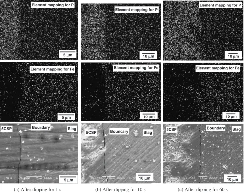
Fig. 2 SEM images and element mappings for P and Fe around interfaces between 5CaOSiO2P2O5and slag A at 1573 K. (5CSP is short
[image:2.595.307.549.84.140.2] [image:2.595.316.532.124.287.2] [image:2.595.53.547.368.759.2]crucible (I.D.: 34 mm, O.D.: 38 mm, Height: 45 mm) with the coexistence of electrolytic iron (about 3 g) to maintain the Fe3þ/Fe2þratio in the slag constant. The crucible was set in the hot zone of the reaction tube (I.D.: 52 mm, O.D.: 60 mm, Length: 1000 mm) at 1573 or 1673 K. High purity Ar gas with a flow rate 700 cm3/min was introduced from the
bottom of the reaction tube. After the slag had been maintained for 3600 s at experimental temperature, the solid 5CaOSiO2P2O5disc attached to the tip of the ceramic tube
by platinum wire was inserted in the reaction tube, suspended slightly above the liquid slag for 120 s to ensure thermal equilibrium, and then dipped into the slag. After dipping for 1 to 600 s, the solid 5CaOSiO2P2O5with adhered liquid
slag was rapidly withdrawn from the reaction tube and quenched by immersing in liquid nitrogen, followed by embedding in the polyester resin. The cross-section was polished and the interface between 5CaOSiO2P2O5and slag
was observed and analyzed by SEM/EDS.
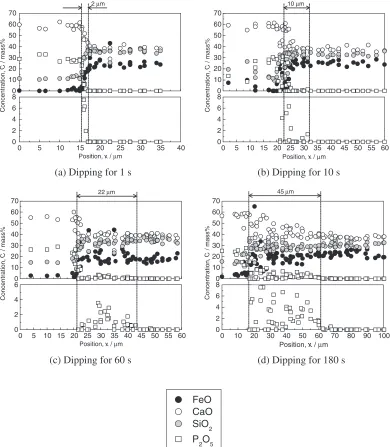
3. Results
Since the initial slag was free of P2O5, the increase of
P2O5 content in the slag is the indication of the dissolution
behavior of solid 5CaOSiO2P2O5. Therefore, the interface
between solid 5CaOSiO2P2O5and slag was analyzed with
special concern given to the concentration profile of P2O5
across the interfaces to evaluate the dissolution behavior. The SEM images of the interfaces between solid 5CaOSiO2P2O5 and slag A after dipping the solid for 1,
10 and 60 s at 1573 K together with the element mapping for P are shown in Fig. 2. The left side of the figure is the original solid 5CaOSiO2P2O5, while the bulk slag is on the right.
As can be seen in these SEM images, the synthesized solid 5CaOSiO2P2O5 pieces were much porous, though the
porosity of solid pieces was not measured in the present study. Therefore, it is believed that the liquid slag penetrated into the solid phase after the solid piece was dipped in the
0 5 10 15 20 25 30 35 40 45 50 55 60 0
2 4 6 8 0 10 20 30 40 50 60 70
Position, x / µm
Concentration,
C
/ mass%
12 µm
0 5 10 15 20 25 30 35 40 45 50 55 60 0
2 4 6 8 0 10 20 30 40 50 60 70
Position, x / µm
Concentration,
C
/ mass%
21 µm
(a) Dipping for 1 s (b) Dipping for 10 s
0 10 20 30 40 50 60 70 80 90 100 110 120 0
2 4 6 8 0 10 20 30 40 50 60 70
Position, x / µm
Concentration,
C
/ mass%
51 µm
(c) Dipping for 60 s
FeO CaO SiO2 P2O5
[image:3.595.103.497.75.524.2]liquid slag. This phenomenon was also confirmed by the fact that the gradual change of color was observed at the cross section of dipped solid 5CaOSiO2P2O5 pieces, while
synthesized 5CaOSiO2P2O5 pieces were purely white. The
boundary between solid 5CaOSiO2P2O5 and slag can be
identified according to the element mapping for phosphorus by EDS across the interface.
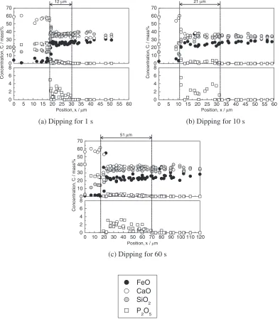
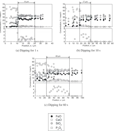
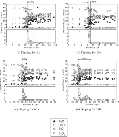
The composition analysis by EDS at different positions across the interface was conducted to observe the concen-tration profiles of the main components in the system. An arbitrary reference location was chosen inside the solid 5CaOSiO2P2O5 phase. The composition at each analyzed
position was recorded as the function of its distance from the reference location as shown in Figs. 3 to 6 for slags A and B at 1573 and 1673 K. In the present study, the iron oxide was calculated as FeO. From solid 5CaOSiO2P2O5(left side) to
bulk slag (right side), CaO and P2O5contents are decreasing
while SiO2and FeO are increasing. It is considered that firstly
the solid compound dissolves and then CaO and P2O5diffuse
into the bulk slag driving by the activity gradient. The penetration of slag into solid phase also occurs.
In order to clarify the diffusion behavior of P2O5, in the
present study the position where CaO and P2O5content start
to decrease while SiO2 and FeO are sharply increasing is
regarded as the boundary between solid 5CaOSiO2P2O5and
slag. According to the concentration profile of P2O5, the
thickness of the diffusion layer of P2O5 can be obtained by
measuring the relative distance between the position where P2O5 content becomes zero and the boundary, as marked in
the figures.
4. Discussion
4.1 Dissolution procedure of solid 5CaOSiO2P2O5into slag
The dissolution procedure of solid 5CaOSiO2P2O5 into
the slag can be divided into three stages as illustrated in Fig. 7. First is interaction, the solid contacts with the liquid
0 5 10 15 20 25 30 35 40
0 2 4 6 8 0 10 20 30 40
Position, x / µm
Concentration,
C
/ mass%
0 5 10 15 20 25 30 35 40 45 50 55 60 0
2 4 6 8 0 10 20 30 40
Position, x / µm
Concentration,
C
/ mass%
(a) Dipping for 1 s (b) Dipping for 10 s
0 10 20 30 40 50 60 70 80 90 100 0
2 4 6 8 0 10 20 30 40 50 60 70
Position, x / µm
Concentration,
C
/ mass%
49 µm
(c) Dipping for 60 s
FeO CaO SiO2 P2O5
[image:4.595.103.496.71.522.2]slag (Fig. 7(a)). Second is disintegration, the rim layer of the solid 5CaOSiO2P2O5 disintegrates into isolated particles
due to the penetration of liquid slag (Fig. 7(b)). Reaction and diffusion are the third stage (Fig. 7(c)). The reaction at the interface between solid particle and surrounding slag is assumed to be instantaneous making the adjacent liquid slag film be saturated with 5CaOSiO2P2O5, though the
satura-tion of liquid slag cannot be confirmed since the liquidus compositions for the CaO-SiO2-FeOx-P2O5 slag saturated
with solid 5CaOSiO2P2O5 have not been reported so far.
Because of the activity gradient, CaO and P2O5diffuse from
the liquid slag film to the surrounding liquid slag. Corre-spondingly the CaO and P2O5contents in the diffusion layer
next to the solid phase increase. The white arrows in the figure show the multi directional local diffusion from the liquid slag film saturated with the solid 5CaOSiO2P2O5
to the surrounding liquid slag in the slag penetration layer. The overall diffusion is regarded from the solid phase to the bulk slag.
In addition, the liquid slag composition rapidly reaches to the solid-liquid coexisting region saturated by 2CaOSiO2
because the initial liquid slag composition is very near from the liquidus saturated with 2CaOSiO2 as shown in Fig. 1.
Therefore, the precipitation of 2CaOSiO2 (more exactly
2CaOSiO2-3CaOP2O5), or the selective dissolution of
3CaOP2O5 from solid 5CaOSiO2P2O5 is expected. As a
whole, dissolution of 3CaOP2O5 proceeds as an overall
dissolution reaction.
The solid particles as depicted in Figs. 7(b) and (c) were not clearly observed from SEM/EDS observations as shown in Figs. 2 to 6. The precipitation of P2O5 rich phase at the
interface between liquid CaO-SiO2-FeOx-P2O5 slag and
2CaOSiO2from EDS analysis was observed in the previous
study.13,14) However, the measured compositions being not on the 2CaOSiO2-3CaOP2O5 tie line but at the region
between liquid bulk slag composition and the tie line. Furthermore, the compositions of P2O5 rich phases moved
toward the 2CaOSiO2-3CaOP2O5 tie line with increasing
0 5 10 15 20 25 30 35 40
0 2 4 6 8 0 10 20 30 40 50 60 70
Position, x / µm
Concentration,
C
/ mass%
6 µm
0 5 10 15 20 25 30 35 40
0 2 4 6 8 0 10 20 30 40 50 60 70
Position, x / µm
Concentration,
C
/ mass%
3 µm
(a) Dipping for 1 s (b) Dipping for 10 s
0 5 10 15 20 25 30 35 40 45 50 55 60 0
2 4 6 8 0 10 20 30 40 50 60 70
Position, x / µm
Concentration,
C
/ mass%
6 µm
0 10 20 30 40 50 60 70 80 90 100 110 0
2 4 6 0 10 20 30 40 50 60 70
Position, x / µm
Concentration,
C
/ mass%
29 µm
(c) Dipping for 60 s (d) Dipping for 180 s
FeO CaO SiO2 P2O5
[image:5.595.102.495.72.524.2]reaction time. It is considered that these phenomena are observed because the initially precipitated 2CaOSiO2
-3CaOP2O5particle are smaller than the spot size of electron
beam (approximately 2mm) and the average composition of solid and liquid phases under the beam spot is measured. The shift of average composition to the tie line is due to the growth of precipitated particle. From above discussion, it is concluded the dispersion of small particles around the solid-liquid interface, which were formed by disintegration of solid 5CaOSiO2P2O5or precipitation of 2CaOSiO2-3CaOP2O5,
are reasonably possible.
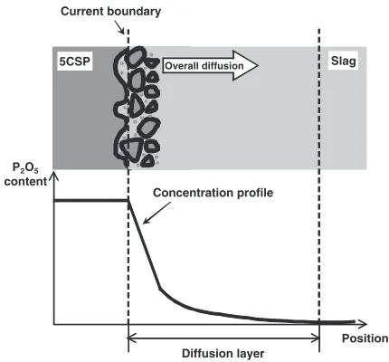
4.2 Estimation of the diffusivity of P2O5 in slag As above mentioned, the region where the change of P2O5
concentration was observed was regarded as a diffusion layer for P2O5. The form of the concentration profile of P2O5 in
liquid phase across the interface is influenced both by the slag penetration into solid phase and the P2O5diffusion into bulk
slag as illustrated in Fig. 8. Since the thickness of the
penetration layer is negligible in most cases in this study, the thickness of the diffusion layer is defined as the distance between the position where P2O5 content turns to zero and
the instant solid/slag boundary.
According to the experimental results shown in Figs. 3–6, the thickness of the diffusion layer was plotted as the function of the square root of dipping time as shown in Fig. 9. Since only one profile for P2O5 concentration has been measured
for each slag composition at each temperature, the obtained values of diffusion layer thickness have been scattered. Nevertheless, the increase of the thickness with the dipping time was observed. Therefore, it is considered that the dissolution of the solid phase is governed entirely by the diffusion in slag.
In order to calculate the diffusivity of P2O5, the following
assumptions are made.
(1) Diffusion of P2O5is single dimensional.
(2) Diffusion time equals the dipping time.
(3) The diffusion of other components such as CaO has
0 5 10 15 20 25 30 35 40
0 2 4 6 8 0 10 20 30 40
Position, x / µm
Concentration,
C
/ mass%
0 5 10 15 20 25 30 35 40 45 50 55 60 0
2 4 6 8 0 10 20 30 40
Position, x / µm
Concentration,
C
/ mass%
(a) Dipping for 1 s (b) Dipping for 10 s
0 5 10 15 20 25 30 35 40 45 50 55 60 0
2 4 6 0 10 20 30 40 50 60 70
Position, x / µm
Concentration,
C
/ mass%
22 µm
0 10 20 30 40 50 60 70 80 90 100 0
2 4 6 8 0 10 20 30 40 50 60 70
Position, x / µm
Concentration,
C
/ mass%
45 µm
(c) Dipping for 60 s (d) Dipping for 180 s
FeO CaO SiO2
P2O5
[image:6.595.103.493.73.520.2]little influence on the P2O5 diffusion.
(4) There are no wall effects.
(5) The concentration at the solid/liquid boundary is constant (P2O5 content in the liquid slag film saturated
with solid 5CaOSiO2P2O5).
(6) There are no convection currents in the liquid slag. The diffusivity (D) of P2O5was calculated based on eq. (1)
derived from above assumptions, whereL andt denote the thickness of diffusion layer and diffusion time, respectively.
L¼4pffiffiffiffiffiDt ð1Þ
Roughly estimated diffusivity of P2O5 in Slag A was 3
1012 and21012m2/s at 1573 and 1673 K, and those in
Slag B was 21013 and 61013m2/s at 1573 and
1673 K, respectively. The value of diffusivity of P2O5in the
CaO-SiO2-FeOx slag has not been found in published
literature. However, the diffusivities of P2O5 in the
30 mass%CaO-45%SiO2-25%Fe2O3 slag at 1623, 1673 and
1723 K measured by Ukyo et al.17) are in the range from 5:51011 to1:61010m2/s, respectively. These values
are slightly larger than the diffusivities calculated in the present study. However, the dependence of diffusivity of P2O5 on the slag composition is not well clarified yet.
The influence of temperature and CaO/SiO2 molar ratio
on the diffusion of P2O5 in slag can be understood from
estimated diffusivities. For slag A, since the difference of diffusivity at different temperature is in the range of experimental error, it is regarded that the temperature has little influence on the diffusion for slag A. However, for slag B, the diffusivity at 1673 K is about three times larger than that at 1573 K, indicating that the higher temperature promotes the dissolution and diffusion considerably. Com-paring the results for slags A and B, the value is much larger in the case of slag with lower CaO/SiO2 molar ratio,
implying that the diffusion is restrained by increasing the CaO/SiO2molar ratio of the slag.
For further understanding of P2O5 behavior in the
CaO-SiO2-FeOx-P2O5 multi phase fluxes, the physicochemical
properties of slags such as the phase diagram, or equilibrium phosphorus partition between solid and liquid phases must be clarified.
5CSP Slag
Initial boundary
(a)Interaction
5CSP Slag
Current boundary Initial boundary
Disintegrated 5CSP
(b) Disintegration
5CSP Overall diffusion Slag
Liquid slag film saturated with 5CSP C2S-C3P particles
(c) Reaction and diffusion
Fig. 7 Dissolution procedure of solid 5CaOSiO2P2O5into slag. (5CSP is
short for 5CaOSiO2P2O5)
P2O5 content
5CSP Overall diffusion Slag
Diffusion layer Current boundary
Position Concentration profile
Fig. 8 Form of the concentration profile of P2O5in liquid phase across the
interface between solid 5CaOSiO2P2O5 and slag. (5CSP is short for
5CaOSiO2P2O5)
0 5 10 15 20
0 10 20 30 40 50 60 70
A at 1573 K A at 1673 K B at 1573 K B at 1673 K
Square root of time, t1/2 / s1/2
Thickness of the diffusion layer,
L
/
µ
m
[image:7.595.63.274.68.467.2] [image:7.595.318.534.74.251.2] [image:7.595.60.275.548.748.2]5CaOSiO2P2O5in the molten CaO-SiO2-FeOxslag at 1573
and 1673 K was investigated. The influence of temperature and CaO/SiO2ratio on the diffusion of P2O5was discussed.
The dissolution of solid phosphate compound into liquid slag can be divided into the following stages: interaction of solid phase with slag, disintegration of solid phase, reaction between disintegrated solid phase and surrounding slag, and diffusion of CaO and P2O5 from solid phase to slag. The
diffusivity of P2O5 in the liquid slag was calculated. Higher
temperature is favored for the diffusion in some cases, whereas higher CaO/SiO2 ratio of the slag restrains the
diffusion.
REFERENCES
1) W. J. Schlitt and G. W. Healy: Am. Ceram. Soc. Bul.50(1971) 954– 957.
2) M. Matsushima, S. Yadoomaru, K. Mori and Y. Kawai: Tetsu-to-Hagane62(1976) 182–190.
5) T. Hamano, S. Fukagai and F. Tsukihashi: ISIJ Int.46(2006) 490–495. 6) H. Suito and R. Inoue: ISIJ Int.46(2006) 180–187.
7) R. Saito, H. Matsuura, K. Nakase, X. Yang and F. Tsukihashi: Tetsu-to-Hagane95(2009) 258–267.
8) S. Fukagai, T. Hamano and F. Tsukihashi: ISIJ Int.47(2007) 187–189. 9) H. Suito, Y. Hayashida and Y. Takahashi: Tetsu-to-Hagane63(1977)
1252–1259.
10) K. Ito, M. Yanagisawa and N. Sano: Tetsu-to-Hagane68(1982) 342– 344.
11) S. Kitamura, H. Shibata and S. Saito: CAMP-ISIJ20(2007) 834. 12) W. Fix, H. Heyman and R. Heinke: J. Am. Ceram. Soc.52(1969) 346–
347.
13) X. Yang, H. Matsuura and F. Tsukihashi: Tetsu-to-Hagane95(2009) 268–274.
14) X. Yang, H. Matsuura and F. Tsukihashi: ISIJ Int.49(2009) 1298– 1307.
15) R. Inoue and H. Suito: ISIJ Int.46(2006) 174–179.
16) K. Utagawa, K. Shimauchi, H. Shibata, N. Maruoka and S. Kitamura: Proc. 4th Int. Cong. on Steelmaking (ICS 2008), (The Iron and Steel Institute of Japan, 2008) pp. 586–589.