For Peer Review
Short stack and full system test using a ceramic A-site
deficient strontium titanate anode
Journal: Fuel Cells
Manuscript ID: fuce.201400183.R2
Wiley - Manuscript type: Original Research Paper
Date Submitted by the Author: 12-Jun-2015
Complete List of Authors: Verbraeken, Maarten; University of St Andrews, School of Chemistry Iwanschitz, Boris; HEXIS AG,
Stefan, Elena; University of St Andrews, School of Chemistry Cassidy, Mark; University of St Andrews, School of Chemistry Weissen, Ueli; HEXIS AG,
Mai, Andreas; HEXIS AG,
Irvine, John; University of St Andrews, School of Chemistry
Keywords: Solid Oxide Fuel Cell, Fuel Cell System, Stack, Anode Catalyst, Supported Catalyst
For Peer Review
Short stack and full system test using a ceramic A-site
deficient strontium titanate anode
Maarten C. Verbraeken1 *, Boris Iwanschitz2, Elena Stefan1, Mark Cassidy1, Ueli Weissen2, Andreas Mai2 and John T.S. Irvine1
1
University of St Andrews, School of Chemistry, KY16 9ST, St Andrews, UK 2
Hexis AG, Zum Park 5, P.O. 3068, CH-8404 Winterthur, Switzerland
Received
[*] Corresponding author, [email protected]
Abstract
A lanthanum and calcium co-doped A-site deficient strontium titanate (LSCTA-) was used as alternative anode material in Solid Oxide Fuel Cells (SOFC) with an active area of 100 cm2. Cell performance was tested in both short (5 cell) stack configuration, as well as a full HEXIS Galileo system (nominally 1 kW AC). Impregnation with various electrocatalysts, such as nickel and ceria, yielded promising fuel cell performance at this scale. The system test initially produced 70% of the nominal output power and is to the authors’ knowledge the first all-oxide SOFC test on this scale. The strontium titanate backbone provides sufficient electronic conductivity to ensure acceptable ohmic losses. Power densities up to 200 mA cm-2 could be obtained at 900°C, which compares well with Ni-cermet based anodes. Degradation is however severe at 900°C, due to impregnate coarsening, but operation at 850°C minimizes this effect. Short stacks could be stably operated for 1600 hours with an output power of 100 mA cm-2. Stacks are redox stable, but currently not sulphur tolerant.
Keywords: Solid Oxide Fuel Cells, Alternative Anodes, Strontium Titanates, Electrocatalysts, Supported Catalysts, Stack Testing, Fuel Cell System
1 Introduction
Solid oxide fuel cells (SOFC) offer an efficient alternative to combustion technology. The good scalability, from stacks producing a few kW up to several MW, makes this technology very flexible with applications ranging from decentralized domestic electricity and heat generation to power plant scale energy production [1, 2].
Current state-of-the-art SOFCs comprise Ni-cermet anodes, where nickel provides both electronic conductivity as well as electrocatalytic activity towards the oxidation of various fuels [3]. Since nickel serves a structural purpose in these anodes, they are particularly prone to degradation resulting from coking, re-oxidation and sulphur poisoning. To overcome these problems, much research has been directed towards finding alternative anode materials.
Doped strontium titanates have been widely studied as potential anode materials in solid oxide fuel cells (SOFCs) [4-7][7][5][6]. The high n-type conductivity that can be achieved in these materials makes them well suited for use as the electronically conductive component in SOFC anodes, making them a potential alternative to nickel. The electrocatalytic activity of strontium titanates tends to be low however, even though B-site doping can enhance this activity [8]. Alternatively, impregnation with oxidation catalysts, such as ceria and nickel seems an effective way to obtain anode performances that can compete with Ni-cermets [9, 10][10]. Here the stability issues due to nickel should be reduced due to the small loadings and its non-structural function.
Here we report a new A-site deficient lanthanum doped strontium titanate, LaxSr1-3/2xTiO3, or LSTA-. A-site deficiency is expected to facilitate lattice oxygen removal [11-13][12][13], thereby creating free electrons according to:
' 1 2 2
2 ( )
O O
O× V•• e O g
→ + + (1)
Recently we presented button cell results comprising a calcium substituted LSTA- based anode. The combination of this material, La0.20Sr0.25Ca0.45TiO3 (LSCTA-) as an anode backbone with ceria and nickel
For Peer Review
impregnates was shown to have comparable performance with nickel cermets, but with superior redox stability. Stable power output was obtained for several hundreds of hours, including 20 redox cycles [14].
Here we present results obtained in both short (5 cell) stack configuration, as well as a HEXIS Galileo system (nominal 1 kW), with an active electrode area of 100 cm2. LSCTA- is used as the ceramic
conductive backbone, with combinations of Ni/CeO2 and Ni/Ce0.80Gd0.20O1.90 impregnated as the electrocatalyst.
2 Experiments
The A-site deficient perovskite material La0.20Sr0.25Ca0.45TiO3 (LSCTA-) was synthesized by Topsoe Fuel Cells A/S, using a drip pyrolysis method [15]. The resulting powder is a nanosized, high surface area powder (40 m2 g-1). The powder is calcined in air prior to ceramic processing, resulting in a d50 particle size ranging between 0.7 and 2.0 µm. The LSCTA- screen printing ink consists of polyvinyl butyral, PVB (Butvar®, Sigma Aldrich) in terpineol (mixture of isomers, Sigma Aldrich), using Hypermer KD1 (Uniqema) as a dispersant. This ink was then used to screen print the anodes onto sintered 6-ScSZ substrates (Nippon Shokubai, Japan) with thickness of 160 µm. Anodes were then fired at 1250°C for 1 hour in air. LSM/YSZ|LSM based cathode and cathode current collector layers were printed on the opposite side of the electrolytes and then fired in air as previously reported[14] (firing conditions
confidential). The anodes were further impregnated with CeO2/CGO (Ce0.80Gd0.20O1.90) and nickel oxide, using nitrate solutions of the respective elements. The nitrates were decomposed by heat treatment in air up to 700°C. Table 1 gives an overview of stacks with the various combinations of electrocatalysts.
The HEXIS stacks are mounted in a non-sealed setup with excess fuel burning on the outside of the cells. Details on the HEXIS test rigs and their operation are described elsewhere [1]. A nickel current collecting mesh is used on the anode side, whereas no mesh is used on the cathode side. The short stacks were run under constant current with standard flow rates of 4 g/h per cell of CPOx reformed natural gas (NG) and 1000 g/h air. The Galileo system test was run under constant gas load (Catalytic Partial Oxidation (CPOx) reformed natural gas), equivalent to 3.3 kW (approx. 4 g/h per cell NG), whilst maintaining a constant stack voltage (larger than 600 mV to avoid ohmic losses due to oxidation of the LSCTA- and hence poor electronic conductivity). Stacks and system were both run with a desulphurising unit.
Fuel cell performance was monitored through a combination of current/voltage measurements and impedance spectroscopy. Impedance was recorded using an IM6 impedance spectrometer in combination with a PP240 potentiostat from Zahner-Elektrik. Impedance spectra were recorded at fixed current densities. Microstructural analysis was performed using a Jeol JSM 6700F FEG-SEM.
Table 1: Different fuel cells tested in this study.
3 Results
Short stack tests
The two short stacks with either Ni/CeO2 or Ni/CGO impregnated catalysts both show good initial performance. Figure 1 shows an IV curve taken after 7 hours of operation at 900°C under standard conditions for Ni/CeO2 as anode catalyst. It shows a close spread of the five cells, with slightly higher area specific resistances (ASR) found for cells 4 and 5. This is also confirmed by the impedance
spectroscopy data, which is shown in Figure 2. The impedance data further shows an ohmic resistance Rs of 0.35 – 0.50 Ωcm2, which is slightly larger than values observed for button cell experiments, i.e. 0.20 – 0.25 Ωcm2 as presented in [14]. The latter were only observed after redox cycling however, which seems to improve contacting between the anode and current collecting mesh. Redox cycling in this study also led to a small improvement, resulting in a stable Rs of ~0.3 Ωcm2. Considering the limited electronic conductivity of LSCTA- [16], ohmic losses were expected to seriously limit the stack performance, especially on this large scale where lateral current distribution is important, but this study proves that this does not pose any major problems. The impregnated LSCTA- cells compare well with standard Ni cermet based cells used at HEXIS as shown in Figure 1b. The polarization is dominated by two processes with relaxation frequencies of 300 – 400 Hz and 0.5 – 0.8 Hz as shown in a Bode plot, Figure 2. The high frequency process was also identified as rate limiting in button cell tests and tentatively attributed to a charge transfer process [14]. The low frequency process is due to gas conversion, as the stacks are run at relatively low gas flows. Another rate limiting step that was observed in button cell tests at 6 – 12 Hz is
For Peer Review
The stack with Ni/CGO as the impregnated electrocatalysts was run at the lower temperature of 850°C, to improve the stack’s long term stability. The power output was therefore lower than the initial performance of the Ni/CeO2 stack as shown in Figure 3. It is however expected that this combination of impregnates should have superior catalytic activity as observed in button cell experiments. Figure 4 shows the difference in anode performance between the two impregnates under identical conditions (900°C, humidified H2) for this type of experiment. It is thought that CGO might enhance oxide ion mobility within the anode and hence give rise to lower polarization for fuel oxidation than observed for CeO2.
Figure 1: IV curve after 7 hours for 5 cell stack with Ni/CeO2 impregnated LSCTA- anode at 900°C in 4 g/h of CPOx reformed natural gas (a). Comparison with standard HEXIS Ni cermet based anode (b)
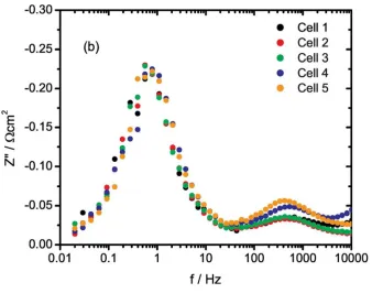
Figure 2: Impedance (a) and Bode plot (b) for Ni/CeO2 impregnated LSCTA- anode in 5 cell stack after 7 hours.
Figure 3: IV curve after 300 hours for 5 cell stack with Ni/CGO impregnated LSCTA- anode at 850°C in 4 g/h of CPOx reformed natural gas
Figure 4: Impedance (a) and IV curve (b) for LSCTA- anode impregnated with either Ni/CeO2 or Ni/CGO at 900°C in humidified H2 from button cell experiments. Impedance has been corrected for Rs to highlight difference in electrocatalytic activity.
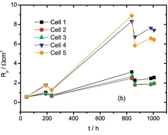
The long term stability of the different stacks can be assessed through Figure 5 and Figure 7. It becomes immediately clear that the Ni/CeO2 5 cell stack is prone to heavy degradation already after 50 – 100 hours of operation at 900°C, whilst running at 200 mA cm-2. Especially cells 4 and 5 show rapid degradation, which seems to destabilize the entire stack. The stack does regenerate somewhat on redox cycling or running at OCV, but degradation does continue after these regeneration cycles. From impedance measurements it is apparent that the degradation seems solely due to an increase in the polarization resistance, Rp, whereas Rs stays constant over approximately 1000 hours of testing, as shown in Figure 6.
Figure 5: Performance of 5 cell stack with LSCTA- anode with Ni + CeO2 as impregnated catalysts at 900°C in 4 g/h of CPOx reformed natural gas.
Figure 6: Evolution of Rs (a) and Rp (b) with time in 5 cell stack comprising LSCTA- anode with Ni + CeO2 impregnates at 900°C. Rs is stable or decreasing over 1000 hour period, indicating degradation is purely due to increase in Rp.
The stack performance of Ni/CGO impregnated LSCTA- is shown in Figure 7. It is evident that this stack shows much improved stability over the Ni/CeO2 based stack. Lower, but stable power output was achieved over 1000 hours at 850°C. This stack was also subjected to redox cycling and showed no signs of degradation due to this treatment.
Figure 7: Performance of 5 cell stack with LSCTA- anode with Ni + CGO as impregnated catalysts at 850°C in 4 g/h of CPOx reformed natural gas.
1 kW Galileo system test
The performance of the 60 cell 1 kW (AC) Galileo system is shown in Figure 8a. The system was run at a gas input of 3.3 kW and constant stack voltage at an average temperature of 850°C. Again the initial performance is good, with a power output of ~70% of the nominal value (some losses occur on AC/DC conversion) as shown by the IV curve in Figure 9a. However, degradation is starting to affect the performance already after ~100 hours of operation, with a steady decline in the power output down to 250 W after 600 hours. The degradation was most severe in the central clusters of the stack, with the most centrally positioned cluster exhibiting a drop in voltage from 700 mV to 300 mV. This is also clear from the difference between IV curves taken after 30 hour and 400 hours, Figure 9. Clusters CL3, CL4 and CL5 show much decreased power output at 400 hours, whereas the remaining clusters perform similarly. On closer examination of the temperature within the stack, it became evident that a large gradient existed
For Peer Review
across the clusters, with the central clusters being at 930°C, whilst the outside clusters being at least 100°C cooler, see Figure 8b.
Figure 8: Galileo system test with LSCTA- anodes impregnated with Ni/CGO (a). Cluster
temperatures, showing large thermal gradient across stack with central clusters (CL3, CL4, CL5) exhibiting temperatures up to 100°C higher than outer clusters (CL1 and CL7)
Figure 9: IV curves for the system test in CPOx reformed natural gas at 850°C after 30 hours (a) and 400 hours (b), showing degradation predominantly in central clusters (CL3, CL4 and CL5)
SEM investigation
Figure 10 shows the SEM micrographs of cells for both the Ni/CeO2 impregnated stack, as well as the Ni/CGO stack/system. It shows that due to some processing issues during the scale up process, the Ni/CGO cells have very thin LSCTA- backbone layers, i.e. 10 – 15 µm with relatively dense
microstructures. The Ni/CeO2 impregnated layers show better porosity and have a layer thickness of ~45 µm to assure good current distribution. A final image shows some nickel particles after 1000 hours of testing at 900°C (Ni/CeO2 stack), demonstrating the large growth from 50 – 100 µm after several tens of hours to 300 – 400 µm.
Figure 10: SEM micrographs of cross section of LSCTA- anode as used in the 5 cell Ni/CGO stack and in the Galileo system test (a), revealing a thin electrode (10 – 15 µm) with relatively dense microstructure. Cross section of the LSCTA- backbone as used in the Ni/CeO2 stack with more porosity and larger thickness (b). Ni/CeO2 impregnated LSCTA- (c, d) after testing at 900°C for 1000 hours, showing nickel particles of 300 – 400 µm.
4 Discussion
The lower power output observed for the Ni/CGO impregnated LSCTA- based cells as compared to Ni/CeO2 can firstly be explained by the lower operating temperature. An IV curve recorded at 900°C for this combination of impregnates however still shows lower performance at this temperature, with peak performance of ~ 125 mA cm-2, i.e. 37% lower than observed for Ni/CeO2. The non-optimized microstructure and thickness of the Ni/CGO impregnated LSCTA- anode is the most likely cause of this lower performance. The average Rs at 900°C for this stack was 0.45 Ωcm2, which is roughly 50% higher than for Ni/CeO2 impregnated stack, which can be explained by poor current distribution through the thin LSCTA- backbone. Due to this poor current distribution and hence reduced active electrode area, Rp is also increased as compared to the Ni/CeO2 stack (before degradation). The LSCTA- backbone in Ni/CGO impregnated cells is also denser, possibly restricting mass transport, but this is not evident from the electrochemical tests.
The large degradation observed in the short stack using Ni/CeO2 impregnated catalysts, already in the early stages of operation is in stark contrast with the button cell results presented previously [14], where stable ASR values were found for over 250 hours of operation. To understand the cause for the severe degradation observed in this study, a careful analysis of the relaxation frequencies of the various electrode processes was carried out. The results are shown in Figure 11. The Bode plot reveals that predominantly the high frequency process (100 – 400 Hz) seems to be affected by the degradation and as a result of this its relaxation frequency drops to 30 – 100 Hz. The increase in its impedance is most likely due to the observed catalyst particle growth, as it is the only obvious change in the system with time. This leads to a reduction in the number of available sites for fuel oxidation and could thus affect the charge transfer step. Alternatively, Primdahl suggested oxide ion transport in CGO as a rate limiting step in Ni infiltrated CGO electrodes [17]. The relaxation frequency and activation energy are similar to the process causing the degradation. Ni sintering may indirectly affect this process, by increasing the diffusion length for oxide ions in either the bulk or on the surface of CeO2/CGO/LSCTA-. The temporary recovery of the Ni/CeO2 impregnated stack upon redox cycling can also be seen from this Bode plot and could be related to refreshment of the Ni surfaces during this process.
Figure 11: Bode plot of LSCTA- with Ni/CeO2 impregnation, showing evolution of relaxation frequencies with time and effect of redox cycling
For Peer Review
assume that catalyst particle growth is one of the main drivers for degradation, as this process proceeds faster at higher temperatures. The system test also confirms the thermal dependence of the main
degradation process. The clusters that were exposed to high local temperatures exhibited much decreased power output after several hundreds of hours, whereas the cooler clusters at the outsides seem to be stable over time. The reason for the large thermal gradient across the 60 cell stack could arise from the larger than usual ohmic resistance in the LSCTA- based anodes, as compared to Ni based cermets. In particular for this system test, the anodes seem to be rather thin too, i.e. 12 – 15 µm, which could lead to further increases in ohmic losses due to poor current distribution. Alternatively, the ceramic anodes may have smaller thermal conductivity in comparison with standard nickel cermet anodes, leading to the large temperature distribution. In contrast, the 5 cell stack utilizing identical LSCTA- anodes with Ni/CGO catalysts showed much improved stability over time. This can be explained by the easier thermal management of a short stack as compared to a 60 cell stack. All cells could be kept within a narrow temperature range around 850°C. Better stability on a system level could be obtained through optimizing anode microstructure (i.e. increased layer thickness and porosity) to improve ohmic losses, but an adjustment of stack design might be required as well if the thermal conductivity of LSCTA- proves to be a limiting factor. Despite easier thermal management of short stacks, the long term performance of the Ni/CeO2 impregnated short stack shows splitting into two poorly performing cells and three cells performing marginally better (Figure 2b). This behavior may originate from poor impregnate distribution due to a non-optimized impregnation technique and hence accelerated degradation at high temperature for some cells.
The much reduced stability of the short stacks operated at 900°C as compared to the button cells reported in [14] is striking. Whereas the button cells showed at least 250 hours of stable operation, in short stack testing, stability issues arise already after ~50 hours. In fact, degradation was also observed in button cells after ~300 hours, but much less pronounced than can be seen in Figure 5. It is the nature of stack tests, that one or two bad cells can bring the whole stack performance down, and it is expected that this is what causes the different behavior between button cells and short stacks.
The sulphur tolerance of these anodes was not tested in detail, but it was established that performance degraded rapidly upon bypassing the desulphurising unit, which is expected to introduce ~8 ppm of H2S to the fuel. This is not surprising, considering that nickel is one of the main catalysts in these stacks and is known to be prone to sulphur poisoning [18]. The degradation due to sulphur was always reversible however, indicating the robustness of these impregnated anodes. Different catalysts with higher sulphur tolerance can easily be impregnated whilst leaving the supporting backbone intact, thus giving minimal additional processing efforts.
5 Conclusions
An oxide ceramic, La0.20Sr0.25Ca0.45TiO3 (LSCTA-), was successfully used as an anode backbone material in a kW scale SOFC system test, which to the authors’ knowledge is the first alternative anode material to Ni based cermets to be tested on an industrially relevant scale. The initial performance of the stacks is comparable to those comprising Ni based cermet anodes, but degradation relating to the impregnated catalysts is still too high. The concept of using an electronically conductive, redox stable ceramic as backbone with electrocatalysts impregnated into the porous structure is proven to be viable, as the stack results show that reasonable ohmic losses can be achieved with excellent stability. In order to keep ohmic losses low, good control of materials processing is required to ensure appropriate layer thickness and porosity for optimum current distribution. The stability of the impregnates requires more attention as was shown by the increase in polarization over several hundreds of hours of testing. The separation of mechanical support, electronically conductive component and electrocatalysts however, offers great flexibility and means that different catalysts with greater thermal stability, and perhaps sulphur tolerance can be impregnated, whilst leaving the backbone intact.
Acknowledgements
The authors gratefully acknowledge funding from the Fuel Cells and Hydrogen Joint Undertaking under grant agreement n° 256730.
References
[1] A. Mai, B. Iwanschitz, U. Weissen, R. Denzler, D. Haberstock, V. Nerlich, J. Sfeir, A. Schuler, ECS Transactions 2009, 25, 149-158.
For Peer Review
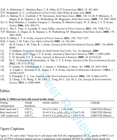
[2] B. A. Haberman, C. Martinez Baca, T. R. Ohrn, ECS Transactions 2011, 35, 451-464. [3] P. Holtappels, S. U., in Handbook of Fuel Cells, John Wiley & Sons, Ltd, 2010.
[4] O. A. Marina, N. L. Canfield, J. W. Stevenson, Solid State Ionics 2002, 149, 21-28; P. Blennow, A. Hagen, K. K. Hansen, L. R. Wallenberg, M. Mogensen, Solid State Ionics 2008, 179, 2047-2058. [5] J. C. Ruiz-Morales, J. Canales-Vazquez, C. Savaniu, D. Marrero-Lopez, W. Z. Zhou, J. T. S. Irvine,
Nature 2006, 439, 568-571.
[6] Q. L. Ma, F. Tietz, A. Leonide, E. Ivers-Tiffee, Journal of Power Sources 2011, 196, 7308-7312. [7] P. Blennow, A. Hagen, K. K. Hansen, L. R. Wallenberg, M. Mogensen, Solid State Ionics 2008, 179,
2047-2058.
[8] D. N. Miller, J. T. S. Irvine, Journal of Power Sources 2011, 196, 7323-7327. [9] R. J. Gorte, J. M. Vohs, Curr Opin Colloid In 2009, 14, 236-244.
[10] M. D. Gross, J. M. Vohs, R. J. Gorte, Journal of the Electrochemical Society 2007, 154, B694-B699.
[11] T. Ishihara, Perovskite Oxide for Solid Oxide Fuel Cells, Vol. 16, Springer, 2009.
[12] P. R. Slater, D. P. Fagg, J. T. S. Irvine, Journal of Materials Chemistry 1997, 7, 2495-2498. [13] C. D. Savaniu, J. T. S. Irvine, Journal of Materials Chemistry 2009, 19, 8119-8128.
[14] M. C. Verbraeken, B. Iwanschitz, A. Mai, J. T. S. Irvine, Journal of the Electrochemical Society
2012, 159, F757-F762.
[15] P. Gordes, N. Christiansen, E. J. Jensen, J. Villadsen, J. Mater. Sci. 1995, 30, 1053-1058. [16] A. Yaqub, C. Savaniu, N. K. Janjua, J. T. S. Irvine, Journal of Materials Chemistry A 2013, 1,
14189-14197.
[17] S. Primdahl, Y. L. Liu, Journal of the Electrochemical Society 2002, 149, A1466-A1472. [18] Z. Cheng, J. H. Wang, Y. M. Choi, L. Yang, M. C. Lin, M. L. Liu, Energy & Environmental
Science 2011, 4, 4380-4409.
Tables
Table 2: Different fuel cells tested in this study. Testing
configuration
Anode backbone
Anode catalyst Cathode
Short stack test 1 LSCTA- 10 wt.% CeO2 + 5 wt.% Ni LSM/YSZ (Hexis) Short stack test 2 LSCTA- 10 wt.% Ce0.80Gd0.20O1.90 + 5 wt.% Ni LSM/YSZ (Hexis) 1 kW system test LSCTA- 10 wt.% Ce0.80Gd0.20O1.90 + 5 wt.% Ni LSM/YSZ (Hexis)
[image:7.612.108.507.66.543.2]Figure Captions
Figure 1: IV curve after 7 hours for 5 cell stack with Ni/CeO2 impregnated LSCTA- anode at 900°C in 4 g/h of CPOx reformed natural gas (a). Comparison with standard HEXIS Ni cermet based anode (b)
Figure 2: Impedance (a) and Bode plot (b) for Ni/CeO2 impregnated LSCTA- anode in 5 cell stack after 7 hours.
Figure 3: IV curve after 300 hours for 5 cell stack with Ni/CGO impregnated LSCTA- anode at 850°C in 4 g/h of CPOx reformed natural gas
Figure 4: Impedance (a) and IV curve (b) for LSCTA- anode impregnated with either Ni/CeO2 or Ni/CGO at 900°C in humidified H2 from button cell experiments. Impedance has been corrected for Rs to highlight difference in electrocatalytic activity.
Figure 5: Performance of 5 cell stack with LSCTA- anode with Ni + CeO2 as impregnated catalysts at 900°C in 4 g/h of CPOx reformed natural gas.
For Peer Review
Figure 6: Evolution of Rs (a) and Rp (b) with time in 5 cell stack comprising LSCTA- anode with Ni + CeO2 impregnates at 900°C. Rs is stable or decreasing over 1000 hour period, indicating degradation is purely due to increase in Rp.
Figure 7: Performance of 5 cell stack with LSCTA- anode with Ni + CGO as impregnated catalysts at 850°C in 4 g/h of CPOx reformed natural gas.
Figure 8: Galileo system test with LSCTA- anodes impregnated with Ni/CGO (a). Cluster temperatures, showing large thermal gradient across stack with central clusters (CL3, CL4, CL5) exhibiting
temperatures up to 100°C higher than outer clusters (CL1 and CL7)
Figure 9: IV curves for the system test in CPOx reformed natural gas at 850°C after 30 hours (a) and 400 hours (b), showing degradation predominantly in central clusters (CL3, CL4 and CL5)
Figure 10: SEM micrographs of cross section of LSCTA- anode as used in the 5 cell Ni/CGO stack and in the Galileo system test (a), revealing a thin electrode (10 – 15 µm) with relatively dense microstructure. Cross section of the LSCTA- backbone as used in the Ni/CeO2 stack with more porosity and larger thickness (b). Ni/CeO2 impregnated LSCTA- (c, d) after testing at 900°C for 1000 hours, showing nickel particles of 300 – 400 µm.
Figure 11: Bode plot of LSCTA- with Ni/CeO2 impregnation, showing evolution of relaxation frequencies with time and effect of redox cycling
Wiley-VCH
For Peer Review
81x56mm (300 x 300 DPI)
For Peer Review
[image:10.612.141.472.131.363.2]Figure 1: IV curve after 7 hours for 5 cell stack with Ni/CeO2 impregnated LSCTA- anode at 900°C in 4 g/h of CPOx reformed natural gas (a). Comparison with standard HEXIS Ni cermet based anode (b)
83x59mm (300 x 300 DPI)
Wiley-VCH
For Peer Review
60x38mm (300 x 300 DPI) 3
For Peer Review
[image:12.612.138.476.132.398.2]Figure 2: Impedance (a) and Bode plot (b) for Ni/CeO2 impregnated LSCTA- anode in 5 cell stack after 7 hours.
83x67mm (300 x 300 DPI)
Wiley-VCH
For Peer Review
[image:13.612.141.472.122.357.2]Figure 3: IV curve after 300 hours for 5 cell stack with Ni/CGO impregnated LSCTA- anode at 850°C in 4 g/h of CPOx reformed natural gas
81x56mm (300 x 300 DPI) 3
For Peer Review
48x23mm (300 x 300 DPI)
Wiley-VCH
For Peer Review
[image:15.612.138.474.127.378.2]Figure 4: Impedance (a) and IV curve (b) for LSCTA- anode impregnated with either Ni/CeO2 or Ni/CGO at 900°C in humidified H2 from button cell experiments. Impedance has been corrected for Rs to highlight
difference in electrocatalytic activity. 83x61mm (300 x 300 DPI)
For Peer Review
Figure 5: Performance of 5 cell stack with LSCTA- anode with Ni + CeO2 as impregnated catalysts at 900°C in 4 g/h of CPOx reformed natural gas.
86x51mm (300 x 300 DPI)
Wiley-VCH
For Peer Review
83x67mm (300 x 300 DPI)
For Peer Review
[image:18.612.142.475.134.402.2]Figure 6: Evolution of Rs (a) and Rp (b) with time in 5 cell stack comprising LSCTA- anode with Ni + CeO2 impregnates at 900°C. Rs is stable or decreasing over 1000 hour period, indicating degradation is purely
due to increase in Rp. 83x67mm (300 x 300 DPI)
Wiley-VCH
For Peer Review
[image:19.612.137.475.131.322.2]Figure 7: Performance of 5 cell stack with LSCTA- anode with Ni + CGO as impregnated catalysts at 850°C in 4 g/h of CPOx reformed natural gas.
86x52mm (300 x 300 DPI)
For Peer Review
86x55mm (300 x 300 DPI)
Wiley-VCH
For Peer Review
[image:21.612.140.476.137.392.2]Figure 8: Galileo system test with LSCTA- anodes impregnated with Ni/CGO (a). Cluster temperatures, showing large thermal gradient across stack with central clusters (CL3, CL4, CL5) exhibiting temperatures
up to 100°C higher than outer clusters (CL1 and CL7) 83x66mm (300 x 300 DPI)
For Peer Review
83x61mm (300 x 300 DPI)
Wiley-VCH
For Peer Review
[image:23.612.138.474.131.372.2]Figure 9: IV curves for the system test in CPOx reformed natural gas at 850°C after 30 hours (a) and 400 hours (b), showing degradation predominantly in central clusters (CL3, CL4 and CL5)
83x61mm (300 x 300 DPI)
For Peer Review
271x217mm (300 x 300 DPI)
Wiley-VCH
For Peer Review
96x77mm (300 x 300 DPI)
For Peer Review
96x77mm (300 x 300 DPI)
Wiley-VCH
For Peer Review
[image:27.612.119.495.112.413.2]Figure 10: SEM micrographs of cross section of LSCTA-¬ anode as used in the 5 cell Ni/CGO stack and in the Galileo system test (a), revealing a thin electrode (10 – 15 µm) with relatively dense microstructure. Cross
section of the LSCTA- backbone as used in the Ni/CeO2 stack with more porosity and larger thickness (b). Ni/CeO2 impregnated LSCTA- (c, d) after testing at 900°C for 1000 hours, showing nickel particles of 300 –
400 µm.
361x289mm (300 x 300 DPI)
For Peer Review
[image:28.612.138.473.135.388.2]Figure 11: Bode plot of LSCTA- with Ni/CeO2 impregnation, showing evolution of relaxation frequencies with time and effect of redox cycling
83x65mm (300 x 300 DPI)
Wiley-VCH