A Framework for Incremental Construction of Real
Global Smart Space Applications
1
René Meier*, Anthony Harrington, Kai Beckmann and Vinny Cahill Distributed Systems Group
Department of Computer Science, Trinity College Dublin, Ireland *Tel: +353 1 896 1261, Fax: +353 1 677 2204
Abstract - This article describes a standardised way to build context-aware global smart space applications using information that is distributed across independent (legacy, sensor-enabled, and embedded) systems by exploiting the overlapping spatial and temporal attributes of the information maintained by these systems. The framework supports a spatial programming model based on a topographical approach to modelling space that enables systems to independently define and use potentially overlapping spatial context in a consistent manner and in contrast to topological approaches, in which geographical relationships between objects are described explicitly. This approach is supported by an extensible data model that implicitly captures the relationships between information provided by separate underlying systems and facilitates the incremental construction of global smart spaces since the underlying systems to be incorporated are largely decoupled. The framework has been evaluated using a prototype that integrates legacy systems and context-aware services for multi-modal urban journey planning and for visualising traffic congestion.
Keywords: Global smart spaces, middleware, spatial programming, context-aware applications
1. Introduction
Global smart spaces extend the vision of pervasive computing, in which everyday objects communicate and collaborate to provide information and services to users, to large geographical areas [1]. They extend the notion of objects cooperating in a home or an office to the level of towns, cities, and even countries by integrating a variety of sensor-based and other systems to provide truly pervasive context-aware services. Such global smart environments will be heterogeneous as they likely will comprise a multitude of sensors, networks, and ultimately systems. They will provide access to information and services ranging from pervasive access to personal and professional information, to city-wide information systems [2, 3], to context-aware traveller assistance [4, 5], to optimised urban traffic control [6]. Users moving in such sensor-augmented spaces may use handheld devices, such as mobile phones and Personal Digital
1
Assistants (PDAs), or integrated devices, such as (vehicular) on-board computers, to interact with these spaces and to use the services that they provide. Embedded control systems may likewise exploit these spaces to offer context-aware urban traffic control, such as public service vehicle priority.
Global smart spaces are on the verge of becoming a reality in the transportation domain where very many heterogeneous sensor-rich systems have already been deployed in towns and cities and along national road networks. Such a global smart space might enable users to access information ranging from places of interest, to prevailing road and weather conditions, to expected journey times, to up-to-date public transport information. It might also enable suitably privileged users to interact with the infrastructure, for example, to request a change to a traffic light or to reserve a parking space.
The basis for the provision of context-aware services and information to users will be the integration of the individual systems associated with global smart spaces into comprehensive platforms. This article presents a framework designed to provide a standardised way to build context-aware global smart space applications using information that is distributed across independent systems and related services. The iTransIT framework supports a spatial programming model based on a topographical location model that provides access to distributed context information based on (overlapping) temporal and spatial aspects. This enables applications to exploit and act upon information from a variety of deployed (and novel) systems and services as well as to share information between them. The spatial programming model hides the complexity and diversity of the underlying systems and their data sources and provides applications with a common view on the available information and its context. For example, a service might use the spatial programming model to retrieve public transport information, which might be provided by some underlying system, and then access relevant weather information provided by another system using the temporal and spatial context of this information.
illustrates that systems may be integrated gradually and with minimal impact on other systems. Each of these layers might be integrated at a different time and the integration of one layer does not affect the data captured in the other layer. An application using the spatial programming model to access information from the video layer might eventually be updated to access the car parking layer as well. The iTransIT framework has been developed in cooperation with the Traffic Office of Dublin City Council (DCC) in the Republic of Ireland. Detailed framework requirements were informed by a comprehensive audit of existing and planned future intelligent transportation systems in the Dublin City area. Other approaches, such as federated databases and data stream management systems [7], address a similar problem in terms of decentralised information processing. However, they imply technological constraints targeted at the requirements of enterprise computing systems rather than at embedded systems as proposed by the iTransIT framework where the focus is on integration of legacy systems and implementations are distributed across systems.
The proposed framework has been realised in the form of a proof-of-concept prototype of a global smart space. The prototype models and captures a variety of real transportation information derived from systems currently deployed in Dublin City and serves as a platform for pervasive services using this transportation information. This framework implementation has been evaluated by integrating independent systems and their information and by building pervasive services for multi-modal urban journey planning and for visualising traffic congestion. Such services can be considered canonical global smart spaces applications since they exploit information generated by a variety of underlying heterogeneous systems in a context-aware manner. The evaluation is based on transportation information relevant to and derived from a real urban environment and demonstrates that our framework enables the integration of individual systems associated with a global smart space into a comprehensive platform and that it provides for context-aware services and ultimately user access to pervasive context information. In general, it is expected that the increased availability of reusable information from a variety of independent systems will enable higher-level policies to be translated more easily into real world actions and will facilitate the emergence of novel transportation applications and truly pervasive context-aware user services.
The remainder of this article is structured as follows: Section 2 surveys related work. Section 3 introduces the spatial programming model and section 4 describes the iTransIT framework for building context-aware global smart space applications. Section 5 presents our evaluation of this work based on a prototypical realisation of a global smart space. Finally, section 6 concludes this article by summarising our work.
2. Related Work
Department of Transportation. Both of these frameworks propose similar architectures promoting a separation of the physical and functional views of a system and assume that individual systems can be developed according to their respective standards for physical and functional organization. These frameworks essentially promote a common, system-wide organization based on standardised functions, such as the KAREN functions [10]. They are similar to the iTransIT framework in that they enable integration of a collection of individual systems. However, they are not concerned with building context-aware global smart space applications and hence, they support neither information-specific (and system-specific) integration requirements nor a means for applications to access context information provided by a wide variety of systems and services. Moreover, the iTransIT framework explicitly promotes extensibility through gradual integration of systems, where systems or parts of systems can be added one at a time, and incremental construction of applications over time and can be considered lightweight compared to KAREN and the National ITS Architecture.
Temporal, spatial and quality of service attributes represent types of meta-data that may be integrated into a context model to provide more intelligent and focused use of data [11]. This approach has been applied in the Nexus framework [12, 13] which provides a common context model infused with spatial information to build world models that are distributed across spaces possessing rich context data sources, known as Augmented Areas. The context model is presented as a global object-based ontology for developing interoperable world models. This interoperability is ensured through the use of a common but large data schema, the Standard Class Schema, to define various world models. The authors have defined a simple spatial query language that can be used to interact with objects representing an Augmented Area. An interface known as an Augmented World model provides a federated global view on all compliant local models. The focus of our framework has been to support a more constrained yet expressive set of abstractions which are used to both facilitate data modelling and to provide the basis for our spatial application programming interface. Using such a constrained set of abstractions simplifies management and maintenance in light of continuously evolving global smart spaces as novel systems are expected to use combinations of existing abstractions.
Smart Messages [15] is a lightweight architecture similar to mobile agents that aims to make Space a first-order programming construct and describes a space-aware programming model for outdoor distributed embedded systems called Spatial Programming. In this model, content or services provided by nodes are accessed using spatial references. These are defined as {space:tag} pairs that are mapped to systems embedded in the physical space. These spatial references are used by various applications to transparently access network resources in a similar fashion to physical memory access using variable names in conventional systems. Our approach to accessing information in a global smart space is more generic compared to this {space:tag}-based naming scheme in that information can be located using multiple context dimensions including space and time as well as any functional aspect of the information. Information can be shared and integrated by exploiting combinations of these aspects and by exploiting overlapping context.
Other related work includes systems that have focussed on addressing specific aspects of building context-aware smart spaces in transportation environments rather than on providing a common context-based integration platform as proposed by the iTransIT framework. TOPAZ [16] is a service-oriented framework that promotes a business-level application model. TOPAZ envisions a global marketplace of telematics services where Infrastructure providers and application providers are independent business entities. TOPAZ provides an open platform and a Web-service-based portal for managing applications, infrastructure and users. While the platform provides a range of core services for service metering, service monitoring, service diagnostics, and for displaying services, especially, through in-vehicle user interfaces [17], it does not support an explicit common context model that enables the use of overlapping context information across independent applications.
There is also a significant amount of ongoing research related to smart spaces in vehicles and on roadsides. Much of this work is driven by safety applications, ranging from driver assistance services to active accident avoidance applications [18]. Proposed approaches aim at addressing security, privacy, reliability and user interface requirements as well as the requirements of communication infrastructures. Such communication infrastructures enable interactions within vehicles, between vehicles and between vehicles and the roadside in light of technologies for sensor, real-time and wireless networks. We consider these approaches orthogonal to our work in the sense that the iTransIT framework may integrate the resulting ITS as legacy systems in a metropolitan-scale smart space.
3. The Spatial Application Programming Model
- 6 -
act upon information from a variety of systems and services as well as to share information between them.
3.1 Abstracting Information and Context
The spatial programming model uses a small set of predefined types for composing information and context, in which context is any information that can be used to characterise the situation of an information element [19], to ensure interoperability between data sets captured across distributed systems. These types are used to model data sets and their context according to the different roles data sets can assume in a global smart space as spatial objects. Spatial objects represent information as a series of parameters and context as attributes. Such types are central to providing applications with a common view on the wide range of information and the associated context that might be available in a global smart space. They hide the complexity and diversity of the independent systems and data sources comprising global spaces and represent the hooks for information integration through overlapping context such as space and time.
Developing such types is non-trivial for any programming model for significant systems and is especially complex for global smart spaces due to the scale and multitude of inter-relationships that exist between sensors, systems, services, users, and their data sets. Lehman et al. [12] suggest an exhaustive ontology for defining how context information can be shared between applications in augmented areas. However, based on our experience with a real global smart space in the transportation domain, we have found that a relatively small number of types suffices to decompose a global smart space domain model. Using a small set of (coarse-grain) types rather than attempting to model the entire world in detail simplifies management and maintenance in light of continuously evolving spaces. Novel systems or services are expected to be modelled using combinations of existing types whereas an exhaustive model might have to be expanded to capture the specific characteristics of novel systems.
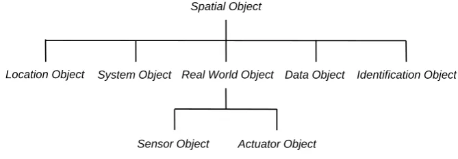
Spatial Object
Identification Object Location Object System Object Real World Object Data Object
[image:6.595.130.465.521.637.2]Actuator Object Sensor Object
Figure 1: Information and context abstractions.
for modelling global information, which are real world, system and data object, as well as types for modelling context.
The three information types model the different roles that objects can assume within the spatial programming model. System objects represent general information describing software components, including systems and services, while real world objects represent physical entities. In a transportation smart space for example, system objects might capture operational status from a car parking system or from a journey time estimation service whereas real world objects might model roads and junctions. Sensor and actuator objects are specialisations of real world objects and are used for modelling explicit infrastructural entities for example, detector loops and variable message signs of a car parking system. Data objects model any static or dynamic information from systems or services and might be used to model car parking opening times and rates charged. Based on an audit of deployed (and planned) transportation systems and services in the Dublin City area [20], we found that these categories of information types are sufficient to cover possible data sets in such a global smart space. Novel information can be integrated using spatial objects composing sets of parameters that model such data sets.
The main context type of the spatial programming model is the location object. Location objects are based on a topographical location model [21] that uses geometry to model the space occupied or covered by an infrastructural element, a system or a service. The spatial programming model also supports temporal context. Temporal context is modelled implicitly, i.e., incorporated in other information types, rather than explicitly as a specific object. This enables information objects to include date and time attributes for representing their temporal context such as creation time and temporal validity. And finally, identification objects provide a type for logical identity, for example, to identify the name of a system or a service.
3.2 Modelling Space
The spatial programming model supports a topographical approach to modelling space. The relevant spatial context of sensors, systems, services and even users is modelled as a geometric shape. Individual shapes are defined by a sequence of coordinates based on a chosen, well-known coordinate system. These shapes explicitly represent spatial context derived form the real world. They may reflect the physical appearances of spatial objects modelling occupied space or may describe areas of interest that specify the regions covered by services. For example, a city-wide car parking system might use the spatial model to define the physical locations occupied by its car parks whereas a road weather service might use the spatial model to outline the locations occupied by weather stations as well as the areas to which reports from individual stations apply.
between spatial objects (and ultimately systems and users) are defined by the position of their respective shape within the common coordinate system. This is particularly significant in global smart spaces where multitudes of independent systems are distributed over large geographical areas and direct communication across systems may be limited or expensive. Applications using the spatial model can exploit these implicit relations to link diverse information together for a user specific purpose. They may access spatially related information, for example, by means of exploiting the distance between shapes or by exploiting containment and intersection relations. This might, for example, enable a vehicle-based information system to retrieve the exact locations of car parking facilities within a certain distance from its current location.
The spatial programming model supports the model for defining geometric shapes defined by the OpenGIS standard [22]. Spatial objects can be represented by geometry types ranging from a point, to a line, to a polygon, to combinations of polygons. Points might be used to define the location of a specific traffic signal or an individual user. Individual polygons might represent the spatial context of a car park or an area of interest whereas a series of (overlapping) polygons might be used to compose a spatial model of a transportation network comprising roads, lanes, and intersections.
As mentioned above, these geometric shapes are specified using a common coordinate system. The selection of such a system depends on the domain of the global smart space for which the spatial programming model is being realised. Coordinates derived from third party location sensors, such as Global Positioning System (GPS) receivers, are mapped onto the chosen reference system if they are based on another system. For example, GPS coordinates may need be converted into a regional reference system chosen for a specific space. The Irish national grid reference system, a system of geographic grid references commonly used in Ireland, has been chosen as the coordinate system in our prototype.
3.3 Modelling Data
SensorObject (from contextabstractions) SystemObject (from contextabstractions) LocationObject (from contextabstractions) IdentificationObject (from contextabstractions) RealWorldObject (from contextabstractions) 1 1 1 1 1 1 1 1 WeatherData WeatherStation 1 1 1 1 DataObject (from contextabstractions) SensorObject (from contextabstractions) SystemObject (from contextabstractions) DataObject (from contextabstractions) LocationObject (from contextabstractions) IdentificationObject (from contextabstractions) RealWorldObject (from contextabstractions) 1 1 1 1 1 1 1 1 WeatherData WeatherStation 1 1 1 SensorObject (from contextabstractions) SystemObject (from contextabstractions) DataObject (from contextabstractions) SensorObject (from contextabstractions) SystemObject (from contextabstractions) DataObject (from contextabstractions) LocationObject (from contextabstractions) IdentificationObject (from contextabstractions) RealWorldObject (from contextabstractions) 1 1 1 1 1 1 1 1 WeatherData WeatherStation 1 1 1 1 LocationObject (from contextabstractions) IdentificationObject (from contextabstractions) RealWorldObject (from contextabstractions) 1 1 1 1 1 1 1 1 WeatherData WeatherStation 1 1 1 RoadWeatherSystem 1..n 1 1..n 1
Figure 2: Modelling a road weather system.
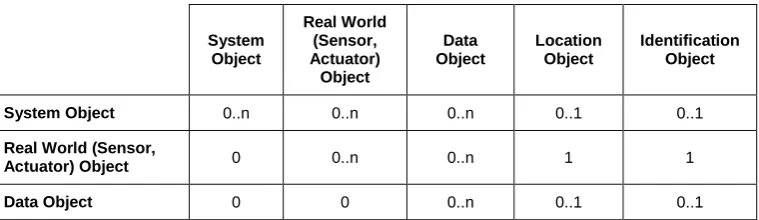
Spatial objects must specialise at least one of our types for modelling information and context. However, depending on their role, they may derive from several types. Table 1 summarises how these types can be combined outlining the semantics for composing information and context into spatial objects. As outlined in the real world object row, Table 1 shows that a real world object must comprise a location and an identification object and that it may include a set of data objects and a set of other real world objects. The compulsory containment of a location object is a reflection of the fact that real world objects are expected to model the physical space they occupy. In contrast, system and data objects may or may not comprise a location object and such a location object is probably modelling the space to which a system’s or data object’s information applies. Note that sensor and actuator objects are specialisations of real world objects that share the same composition semantics.
System Object Real World (Sensor, Actuator) Object Data Object Location Object Identification Object
System Object 0..n 0..n 0..n 0..1 0..1
Real World (Sensor,
Actuator) Object 0 0..n 0..n 1 1
Data Object 0 0 0..n 0..1 0..1
Table 1: The semantics for composing information and context types.
3.4 Modelling Temporal Context
[image:9.595.110.490.525.635.2]infrastructure in Dublin City [20] and are summarised in Table 2. The data object type includes these attributes and spatial objects model their temporal context by deriving from this type.
Applications may exploit temporal relations between spatial objects in the same way as they exploit spatial relations to link diverse information together for a user-specific purpose. They may access temporally related information, for example, by means of correlating modification time. Significantly, applications may exploit context along a combination of the spatial and temporal dimension. This might enable a road-user information system to use the location and time of an accident to retrieve the prevailing weather conditions at the accident site and subsequently to advice drivers of dangerous road conditions.
Attribute Name Description
CreationDate Time of data object creation
LastModificationDate Time the data object was last updated
RetrievalLatency Expected latency for retrieving the captured data
ExpectedLifetime Expected duration to the next data object update
[image:10.595.123.473.260.369.2]ConfidenceLevel Level of confidence in the accuracy of the captured data
Table 2: Temporal context attributes of data object types.
3.5 Using the Spatial Model
Systems use spatial objects to model their contextual information and implement the spatial application programming interface to provide pervasive access to these objects. Each system models the subset of the spatial objects that is relevant to its respective purpose and context-aware applications exploit the spatial application programming interface to integrate and share information in a common way regardless of the specifics of the system implementing a particular part of the spatial model.
bus route in a particular area might identify multiple suitable stops. Spatial objects are uniquely identified within a given system by a type and identifier pair. These pairs are typically the result of some selection operation and may be used to either retrieve or update the parameters of spatial objects. An application might use bus stop and identifier pairs to retrieve the addresses and timetables of previously located stops.
interface S_API {
void insert(String elementType, OrderedParameterValues parValues); void remove(String elementType, int id);
int[] select(String elementType, Geometry loc); int[] select(String elementType, String parName, Parameter parValue);
int[] select(String elementType, Geometry loc, String parName, Parameter parValue);
int[] select(String elementType);
ElementTypeAndId[] select(Geometry loc); Geometry select(String elementType, int id);
void update(String elementType, int id, String parName[], Parameter parValues[]);
Parameter[] retrieve(String elementType, int id, String parName[]);
}
class Parameter{
Calendar creationDate; Calendar modificationDate; Long retrievalLatency; Long expectedLifetime; Double confidenceLevel; String parameterValue;
Integer getIntegerParameterValue(); Double getDoubleParameterValue(); String getStringParameterValue(); Calendar getDateParameterValue(); …
}
4. The iTransIT Framework
The iTransIT framework implicitly captures the relationships between information provided by separate underlying systems. As illustrated in Figure 3, the iTransIT architecture structures legacy systems, iTransIT systems, and context-aware end-user applications into three tiers. These tiers define the relationships between systems and applications and provide an extensible approach for integrating systems and their context information as individual components can be added to a specific tier without direct consequences to the components in the remaining tiers. The relationships between systems and applications can be characterized according to the interaction paradigms that describe the possible information flows between legacy and iTransIT systems.
4.1 Architecture Tiers
The legacy tier provides for the integration of legacy systems and describes existing as well as future transportation systems that have not been developed to conform to the iTransIT system architecture and layered data model. Such legacy systems often feature a form of persistent data storage and might include systems for traffic and motorway management that have commonly been deployed in many urban environments.
The purpose of the iTransIT tier is to integrate transportation systems that model spatial objects and implement the spatial application programming interface. This tier therefore comprises a federation of transportation systems that implement the spatial data model. The data model is distributed across these iTransIT systems, with each system implementing the subset of the overall model that is relevant to its operation. iTransIT systems maintain their individual information, which is often gathered by sensors or provided to actuators, by populating the relevant part of the spatial data model. However, some of the information maintained in an iTransIT system specific part of the data model may actually be provided by underlying legacy systems. Most significantly, traffic information captured in this tier is maintained with its temporal and spatial context; persistently stored data is geo-coded typically by systems exploiting a database with spatial extensions.
Data Flow Application
Tier (User Services)
iTransIT Tier (iTransIT Systems)
Legacy Tier (Legacy Systems)
Geo-Data
Traffic Data Mgmt.
System Type 1
Type 4
Type 2 Type 3
[image:13.595.165.434.102.367.2]Type 5
Figure 3: iTransIT framework overview.
The application tier includes value added (pervasive) services that provide context-aware user access to and interaction with traffic information. These services use the distributed data model and the associated context to access information potentially provided by multiple systems and might include a wide range of interactive (Internet-based) and embedded control services ranging from monitoring of live and historical traffic information to the display of road network maps.
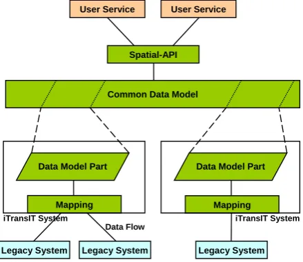
4.2 Common Spatial Data Model
The spatial data model, common to all iTransIT systems, is comprised of a set of potentially distributed layers and represents the central component of these systems. As shown in Figure 4, individual iTransIT systems implement one or more of these layers (or parts of layers) and maintain the static, dynamic, live, or historical traffic data available in a particular layer. For example, a system might implement a data layer describing the current weather conditions while another layer capturing intersection-based traffic volumes might be maintained by a different system.
The spatial application programming interface exposes this layered data model to other iTransIT systems or indeed user services. Remote access to this interface may be enabled through widely used communication technologies and query languages based on CORBA and Web Services.
described using a set of flow classes, including event, stream, request/response, configuration and alarm flows, based on the characteristics and requirements of communication links provided by the KAREN framework architecture [23]. Using these descriptions, individual iTransIT systems implement interfaces that map specific legacy data to their data layers. This approach enables the use of communication technologies that can address the requirements of particular systems and their respective data flows. The objective of an iTransIT system might be to handle a certain data subset efficiently and to provide specific guarantees for the delivery of the data. For example, an iTransIT system may employ real-time communication technology to connect to a legacy system that is capable of supporting strong delivery guarantees.
iTransIT System
Legacy System Legacy System
User Service
Mapping
User Service
Spatial-API
Common Data Model
Data Model Part
iTransIT System
Legacy System Mapping Data Model Part
[image:14.595.189.409.260.450.2]Data Flow
Figure 4: iTransIT system architecture and common data model.
4.3 Data Model Layers
The spatial data model is a multi-layered object data model that has been designed to be extensible and inherently distributed across a range of diverse ITS. Data layers differ in the type of information captured in terms of level of detail and similarity. The data model is built using our abstractions for modelling spatial objects that have been developed to represent key aspects common to all ITS data sets. Principal among these is the spatial aspect of ITS data that is captured by geo-coding all system data.
information associated with individual ITS. A layer typically represents the set of information generated or used by a specific system. New ITS are integrated through the composition of a new system data layer representing the data of that new ITS. For example, a system data layer might be added to integrate the data from a road weather system.
Interoperability. Spatial object types are used throughout the data model in order to ensure interoperability between data layers. When a new system data layer is composed, data elements are built using spatial objects that classify data elements according to their location, identification, and role within the data model. Using this model-wide classification, data from diverse systems can be combined to provide new applications and user services.
Distribution. The data model may be distributed across multiple ITS with individual systems maintaining one or more layers of the overall data model. This potential distribution of layers across a series of systems effectively allows users to access elements of a certain part of the model with a specific quality of service. Hence, this provides a means to share data while accommodating application specific quality of service requirements. For example, a Journey Time Estimation service that uses CCTV sensors for license plate recognition can obtain the plate identification data from an iTransIT Management system whereas a real-time incident detection system using CCTV sensors might require a streamed input data flow.
Physical equipment layer Transport Network Layer Geographic Data Layer
Global View Layers
Traffic Count System Journey Times System
Car Parking System Road Weather System
[image:15.595.189.406.384.490.2]System View Layers
Figure 5: Data model layers.
Extensibility. To ensure extensibility in the spatial data model, a multi-layered approach to modelling has been adopted. The data model is composed of global and system layers representing regional and infrastructural data and individual ITS data sets respectively. A cross-section of the model layers is illustrated in Figure 5. The following three layers describe the global view of the data model.
Geographic Data Layer. This layer contains information relevant to the geographical region in which ITS are deployed. This layer contains topological data and political geographic data, such as district names and boundaries.
related to road lanes and the set of legal turning manoeuvres, as well as profiles of the links connecting junctions.
Physical Equipment Layer. This layer contains information relevant to ITS equipment and installations and includes data on signal controllers, detector loops, traffic bollards, parking meters, and variable message sign installations. Such physical equipment is characteristically modelled using types describing sensor and actuator elements.
These global context layers typically contain static information or information that has a long lifetime. However, they may also accommodate dynamic or rapidly changing information. Examples of static information might include district and road network descriptions whereas dynamic information often includes data that is relevant to the operational status of ITS equipment, such as traffic volumes and congestion levels. Based on our experience with ITS in the Dublin City area, we have found that systems such as a Sydney Coordinated Adaptive Traffic System (SCATS) [24, 25] and a Congestion Level application [26] may supply information for global context layers.
System view layers in contrast characteristically capture information of a specific ITS that often consist of mainly dynamic data. Examples of such system view layers, again taken from the Dublin City region, are shown in Figure 5. Of these, an Urban Journey Time Estimation system [27], might be modelled using a system layer that contains journey time values along with their respective time of day and traffic volumes. Such information may then be cross-referenced to the relevant sections of the road-network using their spatial context.
4.4 Interaction Paradigms
The iTransIT framework overview shown in Figure 3 also identifies five different roles for iTransIT systems described by the communication paradigms used to interact with other iTransIT systems, legacy systems, or user services. These paradigms essentially characterize possible flows of information and systems exploiting them are termed accordingly. Identifying suitable roles using interaction paradigms represents an initial step towards integrating a system or service into an iTransIT architecture. An implementation of the iTransIT architecture may consist of one or more of each of these system types and specific systems may integrate one or more interaction paradigms.
System Type 1 - Dedicated User Service. These systems interface to one or more specific legacy systems and make data available to user services. Such systems can be used to provide context data to or capture context data from legacy systems. Data may simply be passed on or may be processed by an integrated transport management application. An example of a dedicated user service might include a remote configuration platform.
System Type 2 - Legacy System Mediator. These systems enable direct interaction between two or more legacy systems, for example, when exchanging information that exhibits bandwidth requirements that cannot be supported by an iTransIT Management system.
systems often calculate historical information using sensor information maintained in a remote data layer. For example, they may capture hourly traffic volumes in order to generate daily and monthly congestion level reports.
System Type 4 - Universal User Service. These systems may use information generated by a variety of iTransIT systems and combine them to provide “value added information” to users. For example, they may use individual journey time information in combination with weather data and road-work schedules to provide context-aware journey time estimations.
System Type 5 - Dedicated Processor. These systems implement mechanisms that reuse data from other iTransIT systems, process this information and forward the results to specific legacy systems. For example, when providing feedback on traffic volume from a novel iTransIT compatible car parking system to a legacy congestion level system.
Dedicated user service, legacy system mediator, and dedicated processor systems will require mappings to specific legacy systems while universal processor and universal user service systems will have been designed to use the spatial programming model interface to facilitate data exchange. This will facilitate the more rapid integration of these latter system types.
Table 3 summarizes the iTransIT systems roles as well as the data flows associated with each particular interaction paradigm and system type.
System Type Flow Source Flow Sink
Dedicated User Service
Legacy System User Service
User Service Legacy System
Legacy System Mediator Legacy System Legacy System
Universal Processor Mgmt. System Mgmt. System
Universal User Service
Mgmt. System User Service
User Service Mgmt. System
Dedicated Processor
Mgmt. System Legacy System
[image:17.595.134.460.399.560.2]Legacy System Mgmt. System
Table 3: Data flow sources and sinks for each of the system types.
4.5 Data Flow Model
Once a new data layer has been composed, for example, to facilitate the integration of an additional system into the iTransIT framework, the information flows between system components are analyzed using these data flow classes and their attributes. Establishing the characteristics of such data flows is of central importance in the selection and design of appropriate communication technologies for mapping data model elements onto underlying ITS systems and consequently have a direct impact on the quality of data access including retrieval latency and expected lifetime.
The following flow classes have been chosen to represent all data flows in the iTransIT framework.
Event Flow. This class represents data flows that are characteristically driven by an initiating component or source system that determines initiation time and frequency of specific information transfers, provides the information, and designates the intended system component or sink for which the information is destined. Event flows are logically asynchronous and often implemented by an asynchronous messaging protocol.
Request/Response Flow. This class represents data flows that are characteristically driven by a requesting component, i.e., by the component at which the actual information flow is terminated. This component determines initiation time and frequency of specific information transfers, implicitly designates the component for which the information is intended, and explicitly determines the information providing component. Request/response flows are typically synchronous and implemented by a synchronous protocol.
Alarm Flow. This class represents data flows that are essentially specializations of event data flows but differ in the nature of the information flow (from the user’s perspective) that they represent. Event flows illustrate information that typically describes normal system operation whereas alarm flows often indicate information that describes some fault or exception condition.
Configuration Flow. This class represents data flows that are characteristically generated by a source component that that may be required in order to configure another component. Such flows although asynchronous by nature, may be implemented by a synchronous means. The concept of a session is often utilised for this purpose allowing one component to establish a configuration session with another component. Such sessions may comprise several data exchanges between the parts involved.
Stream Flow. This class represents data flows that consist of sequences of related messages. Such streams may be requested by a terminating component or may be commenced by an initiating component. Since stream flows represent sequences of messages they typically depict information flows with a higher volume of data compared to the previously introduced data flow classes. Audio and video data are canonical examples of stream flows. However, streams may also represent sequences of ASCII data.
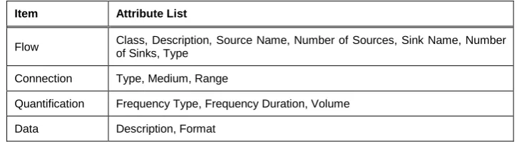
different flow aspects as well as ranges of valid attribute values. However, details of these value ranges have been omitted due to space limitations.
Item Attribute List
Flow Class, Description, Source Name, Number of Sources, Sink Name, Number
of Sinks, Type
Connection Type, Medium, Range
Quantification Frequency Type, Frequency Duration, Volume
[image:19.595.115.478.151.251.2]Data Description, Format
Table 4: Attributes of data flow classes.
5. Evaluation
This section evaluates the framework for building global smart space applications proposed in this article. The framework has been evaluated using a prototypical implementation of an iTransIT Management system for a real urban environment. The iTransIT Management system integrates real transportation information from independent legacy systems and serves as a platform for pervasive services using this information.
5.1 The iTransIT Prototype
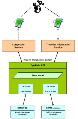
This evaluation is based on a prototypical implementation of an iTransIT Management system that integrates various static and dynamic legacy data from a range of independent systems into a platform for pervasive services. Figure 6 illustrates the prototype and the systems and services that compose this proof-of-concept global smart space.
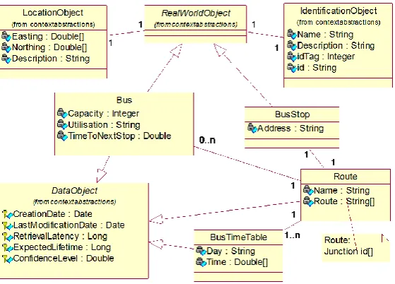
The core of the prototype is the iTransIT Management system that implements the spatial application programming interface and uses spatial objects to model information concerning a range of transportation systems currently deployed in Dublin City. The system includes global context layers modelling the road network comprising intersections, roads, lanes, traffic counts, traffic volumes, and congestion levels as well as the public transport network consisting of bus and tram routes, stops, timetables, bus and tram locations, and bus lanes. It also includes system context layers modelling parking information and road weather data. These layers integrate static and dynamic data provided by a range of real legacy systems including the main traffic management system, a public transport information service, a congestion level application, a road weather service and a car parking information system. Figure 7 shows a small set of the spatial objects modelling these layers that have been implemented as relational tables in a MySQL database with spatial extension. The information from these spatial objects has been provided by the traffic management system, the public transport information service and by a journey time monitoring system.
The two legacy systems shown in Figure 6 are of particular interest for this evaluation. Both of them emulate the real interface of existing transportation systems and use real data from these systems to populate the data model with static and dynamic information on public transport, including routes, timetables and vehicle locations, and on road network traffic congestion. These two legacy systems connect to the Management system using different communication technologies. Information received by the Management system is initially converted into an XML-based format before being translated into SQL statements for populating the data model. In addition to ensuring realistic information exchange, this approach of using real legacy interfaces and real data is expected to enable a transparent switch over from our prototypical legacy system simulators to the real systems without changes to either the Management system or the pervasive services.
congestion levels. Such information enables travellers to adjust their journey routes and to avoid high-congestion areas depending on context such as the time of day or prevailing weather conditions. Such services can be considered canonical global smart spaces applications since they exploit context information generated by a variety of independent systems.
Congestion Service
iTransIT Management System
Spatial - API
XML to DM
CORBA to XML
XML to DM
SCATS to XML
Public Transport Simulator CORBA IDL
Traffic Congestion Simulator SCATS Interface
Data Model
[image:21.595.170.440.167.576.2]Traveller Information Service
Figure 6: Systems and services integrated by the iTransIT prototype.
Figure 7: Spatial objects modelling public transport information.
5.2 Integrating Independent Systems and Services
This experiment evaluates the interactions between the independent legacy systems and the context-aware pervasive services integrated into a global smart space. Specifically, the latencies for exchanging dynamic information between the iTransIT Management system and the legacy systems populating the data model as well as between the iTransIT Management system and the services using the spatial programming model to access information from the data model are assessed. Interactions are based on transportation information exchanges during a weekday, from 5:45 am (when tram services start) to mid afternoon, thereby covering morning and lunch-time rush hours.
Traffic Congestion Legacy System. These measurements assess the interactions between the Traffic Congestion legacy system and the iTransIT Management system. They capture the latencies incurred by the Management system when processing and integrating congestion level updates from the Traffic Congestion system. The Management system uses the interface of the SCATS Traffic Congestion system to periodically request congestion updates. Updates are requested every minute for all 1304 intersections currently covered by our road network model and the presented results are averaged over 5 minute periods.
[image:22.595.104.492.606.717.2]Figure 8 shows a breakdown of the update latency indicating the latencies for requesting updates from the remote legacy system, for converting updates to XML and for converting the XML updates to SQL statements. The latter also includes execution of the SQL statements in order to refresh the data model (database). Figure 9 illustrates the total update latency indicating that processing a single request for updates on all congestion levels in the data model averages at 1358ms and that this duration is steady, which is to be expected considering that the number of congestion levels to be updated (also shown in Figure 9) remains constant.
Figure 9: Overall congestion level update latency.
Figure 10 and Figure 11 show latency measurements for scenarios similar to Figure 8 and Figure 9 respectively. However, the strategy for updating the data model is now based on caching congestion updates received from the legacy system, where congestion levels are only processed if they differ from previous levels. As outlined in Figure 11, this approach significantly reduces the number of processed congestion levels and consequently the number of levels to be updated in the data model. Overall latency is initially high as all levels need be updated and is significantly reduced afterwards, with minor peaks during morning rush hour and at lunch time when levels are expected to change more frequently.
[image:23.595.105.492.496.602.2]Figure 11: Overall congestion level update latency using a caching strategy.
Public Transport Legacy System. These measurements assess the interactions between the Public Transport legacy system and the iTransIT Management system. They capture the latencies incurred by the Management system when processing updates on the locations of the trams of the two lines currently operating in Dublin’s inner city. These location updates are asynchronously disseminated using the CORBA notification service. A notification, which is also called event, is generated for every location update and the presented latencies are averaged over 15 minute periods.
[image:24.595.103.492.427.538.2]Figure 12 shows a breakdown of the latency for refreshing tram locations in the data model. The latency for event dissemination averages at 77ms with 200ms peaks shown during rush and lunch hours. The latency for event queuing shows similar peaks and has been found to be most significant while, in comparison, the latency for event conversion to XML is negligible.
Figure 12: Latency breakdown for updating the tram locations in the data model.
Figure 13: Overall tram location update latency.
Congestion Service. These measurements assess the interactions between the user service for visualising traffic congestion in the road network and the iTransIT Management system. They capture the latencies incurred by the Congestion Service when using JAVA remote method invocation and the spatial programming interface to request congestion levels from the data model. Congestion levels for all 1304 intersections are polled every minute and the latencies are averaged over 5 minute periods. Figure 14 depicts the latencies for requesting a list of all intersection prior to each polling of the congestion levels for all intersections and for polling of the congestion levels while requesting the intersection list only once at initialisation time. The ability to dynamically request newly available congestion levels (and to dynamically ignore discarded congestion levels) increases the average polling latency from 1254ms to 1326ms.
Figure 14: Overall congestion level request latency.
5.3 Incremental Construction of Global Smart Spaces
[image:25.595.103.493.419.526.2]convert XML-based legacy data from other legacy systems. The feasibility and usefulness of such a component has been assessed by subsequently integrating the Public Transport system and reusing this translator.
Table 5 summarises the programming effort required for the individual integration activities of the two legacy systems. Note that these results reflect effort for prototypical programming activities by an experienced researcher only, i.e., they exclude other software engineering activities such as requirements analysis and documentation. The efforts of the realisation activities for the Public Transport system are generally higher than those for the Traffic Congestion system with the exception of the XML to SQL conversion activity. This activity illustrates the high initial effort for realising the generic translator component when integrating the Congestion system and the significantly lower effort for subsequent reuse when integrating the Transport system.
Realisation Activity Traffic Congestion Legacy System Effort [h]
Public Transport Legacy System Effort [h]
Legacy System Communication 3.2 7.5
Legacy Data Queue n/a 6.0
Legacy Data to XML Translator 10.8 13.0
XML to SQL/DM Translator 20.9 2.5
[image:26.595.104.492.307.423.2]Total 34.9 29.0
Table 5: Programming effort for integrating independent legacy systems.
Table 6 outlines the specific programming effort for the XML to SQL conversion realisation activity. The number of Lines of Code (LoC) used for realising this component for integrating the Traffic Congestion legacy system and for integrating the Public Transport legacy system are shown. Of the eleven Java classes realising this component for the Traffic Congestion legacy system integration, eight classes can be reused without change for the Public Transport legacy system integration while three classes require minor extensions (as opposed to modifications). These extensions are straightforward descriptions of the SQL statements updating the database with the new legacy system data. This enables easy reuse of this component as most classes can be reused directly and changes are contained to minor extensions to a small number of classes.
XML to SQL/DM Translator Java Classes
Traffic Congestion Legacy System
Effort [LoC]
Public Transport Legacy System
Effort [LoC]
Effort Increase [Additional LoC]
1: DataObject 199 199 0
2: IdentificationObject 99 99 0
3: LocationObject 58 58 0
4: PayloadData 121 121 0
5: DM_GenericObject 159 159 0
6: XML2DM 431 431 0
7: DM_Translator 57 57 0
8: ITransIT_table_const 39 39 0
9: DM2JDBC 154 159 5 (3.2%)
10: SQL_StatementGenerator 563 714 151 (26.8%)
11: DM2SQLstring 128 161 33 (25.8%)
[image:27.595.104.492.102.355.2]Total 2008 2197 189 (9.4%)
Table 6: Lines of Code for the “XML to SQL/DM Translator” legacy system integration activity.
5.4 Programming Global Smart Space Applications
This experiment evaluates the feasibility of the programming model of our framework providing access to information captured by our data model in a context-aware manner. The evaluation scenario includes a tourist using the context-aware Traveller Information service to locate public transport stations within walking distance of her current location. The tourist has just visited The Book of Kells museum at Trinity College Dublin and is about to leave campus through the Nassau Street gate. She remembers that she used the number 15 bus to travel from her hotel to the city centre and would therefore like to locate nearby bus stops of this route.
1 int[] busStopId = sapi.select("BusStop", searchArea); for (int i = 0; i < busStopId.length; i++) {
2 Parameter busStopName = sapi.retrieve("BusStop",
busStopId[i],"Name"); 3 Geometry busStopLocation = sapi.select(“BusStop”, busStopId[i]); 4 Parameter linkToRoute = sapi.retrieve("BusStop", busStopId[i], "route_autoId");
int routeId = linkToRoute.getIntegerValue();
5 Parameter routeName = sapi.retrieve("Route", routeId, "Name"); 6 if ((routeName.getStringValue().equals(“15-outbound”)) || (routeName.getStringValue().equals(“15-inbound”))) { 7 //use results
} }
The service might use a geometric query to locate all spatial objects representing bus stops in the given search area (1) and retrieve the parameters and attributes of these objects that describe the names and locations of specific bus stops (2, 3). The service then proceeds to identify the spatial objects that describe the routes associated with these bus stops. These “links” to route objects are modelled as parameters that can be retrieved from bus stop objects (4). They are subsequently used to retrieve the names of the bus stop routes (5) and information related to the previously indicated bus route (6) can then be used to advise the user (7). The results of such a scenario for locating bus stops within walking distance can be found in Table 7. Bus stops for both city centre-bound and suburb-bound stops have been retrieved since the user did not specify her preferences. Naturally, a Traveller Information service would display this information as an overlay to a map of Dublin City rather than in table form. Such an overlay might include the bus stop names and the headings of buses. This might further assist the user in locating and eventually walking to a convenient bus stop.
Bus Stop Name Route Name Bus Stop Location
(Irish national grid coordinates)
Kildare Street 15-outbound (316230.8575, 233593.6385)
Dawson Street Upper 15-inbound (316063.4310, 233792.1260)
Dawson Street Lower 15-inbound (316036.3947, 233612.0083)
Suffolk Street 15-inbound (315924.9190, 233981.6965)
Nassau Street 15-outbound (316202.2930, 233883.7390)
[image:28.595.113.490.105.271.2]College Green 15-outbound (316038.3422, 234186.3123)
Table 7: Locating public transport stations within walking distance.
hotel to locate a convenient stop near her destination and to display the route the bus will take. Other related scenarios might include using the Congestion service to retrieve the congestion levels along the route in order to get an indication of whether the bus is likely to be on time. Such a scenario might also be of interest to someone travelling by car to the airport or to work. These related scenarios have been implemented but due to space limitations are not described in further detail.
This application scenario furthermore illustrates how a Java-based realisation of a service can access information from the data model using element type and location context. Using a geographical scope further limits the number of retrieved spatial objects to a subset of the typed objects captured in the data model. Larger search areas are more likely to yield spatial objects that are relevant to the service user and possibly identify alternative objects of interest. The results of queries using smaller-sized search areas can be retrieved and processed more efficiently reducing computational load and can increase clarity from a user’s perspective. For example, using a larger search area might provide a traveller with alternative bus stops but will impose increased computational load on the handheld device for displaying these additional stops. It will also require the traveller to manually eliminate a larger number of unsuitable stops.
This evaluation is based on scenarios that access information integrated in the framework through a single spatial application programming interface. However, a context-aware user service may concurrently use multiple spatial application programming interfaces to access spatial objects in a similar way. The overlapping context of such distributed spatial objects may be used similarly to correlate objects. For example, the location of a bus stop available from one spatial application programming interface might be used to locate nearby train stations through another interface. Also, the framework does not impose a specific programming language for realising spatial application programming interfaces. A programming language other than Java may be chosen based on system and service requirements, for example, to provide a more performance efficient runtime.
6. Summary and Conclusions
information provided by separate underlying systems and facilitates the incremental construction of global smart spaces over time while minimising the impact of such expansion as changes are largely local to the new system or service. The data model is distributed allowing individual systems to maintain one or more layers of the overall data model and facilitating data exchange between systems and services with diverse contextual data sets and functional organizations.
This framework has been evaluated by building a proof-of-concept prototype of a global smart space. The prototype integrates real transportation information derived from independent systems currently deployed in Dublin City and realises context-aware services based on this information. The evaluated scenarios demonstrated that our framework enables the integration of individual systems associated with a global smart space into a comprehensive platform for the provision of truly pervasive context-aware services and information to users.
Acknowledgements. The work described in this article was partly supported by the Dublin City Council in the Republic of Ireland. The authors would also like to thank the Traffic Office of the Dublin City Council for providing the transportation data that made the evaluation of this work possible.
References
[1] A. Dearle, G. Kirby, R. Morrison, A. McCarthy, K. Mullen, Y. Yang, R. Connor, P. Welen, and A. Wilson, "Architectural Support for Global Smart Spaces," in Proceedings of the 4th International Conference on Mobile Data Management (MDM 2003), LNCS 2574. Melbourne, Australia: Springer-Verlag, 2003, pp. 153-164.
[2] K. Cheverst, N. Davies, K. Mitchell, A. Friday, and C. Efstratiou, "Experiences of Developing and Deploying a Context-aware Tourist Guide: The GUIDE Project," in Proceedings of the Sixth Annual International Conference on Mobile Computing and Networking (MobiCom 2000). Boston, Massachusetts, USA: ACM Press, 2000, pp. 20-31.
[3] G. D. Abowd, C. G. Atkeson, J. Hong, S. Long, R. Kooper, and M. Pinkerton, "Cyberguide: A Mobile Context-Aware Tour Guide," ACM Wireless Networks, vol. 3, pp. 421-433, 1997.
[4] T. Sivaharan, G. Blair, A. Friday, M. Wu, H. Duran-Limon, P. Okanda, and C.-F. Sørensen, "Cooperating Sentient Vehicles for Next Generation Automobiles," presented at The First ACM International Workshop on Applications of Mobile Embedded Systems (WAMES'04), Boston, Massachusetts, USA, 2004.
[5] J. Kjeldskov, S. Howard, J. Murphy, J. Carroll, F. Vetere, and C. Graham, "Designing TramMateña Context-Aware Mobile System Supporting Use of Public Transportation," in Proceedings of the 2003 Conference on Designing for User Experiences. San Francisco, California, USA: ACM Press, 2003, pp. 1-4.
[7] M. Garofalakis, J. Gehrkle, and R. Rastogi, "Data Stream Management: Processing High-speed Data Streams," Springer-Verlag Berlin and Heidelberg GmbH & Co., 2007.
[8] European Commission, "The KAREN European ITS Framework Architecture," http://www.frame-online.net, URL accessed in 2008.
[9] U.S. Department of Transportation, "The National ITS Architecture Version 5.0," http://itsarch.iteris.com/itsarch, URL accessed in 2007.
[10] R. A. P. Bossom, O. LeGuellec, A. Nigro, and P. Jesty, "European ITS Framework Architecture - Functional Architecture (D3.1)," European Communities, 2002.
[11] N. Hönle, U.-P. Käppeler, D. Nicklas, T. Schwarz, and M. Grossmann, "Benefits of Integrating Meta Data into a Context Model," in Proceedings of the 2nd IEEE PerCom Workshop on Context Modeling and Reasoning (CoMoRea 2005). Kauai Island, Hawaii, USA: IEEE Computer Society, 2005, pp. 25-29.
[12] O. Lehmann, M. Bauer, C. Becker, and D. Nicklas, "From Home to World - Supporting Context-aware Applications through World Models," in Proceedings of Second IEEE International Conference on Pervasive Computing and Communications (Percom'04). Orlando, Florida: IEEE Computer Society, 2004, pp. 297-308.
[13] M. Grossmann, M. Bauer, N. Hönle, U.-P. Käppeler, D. Nicklas, and T. Schwarz, "Efficiently Managing Context Information for Large-scale Scenarios," in Proceedings of the Third IEEE International Conference on Pervasive Computing and Communications (PerCom 2005). Kauai Island, Hawaii, USA: IEEE Computer Society, 2005, pp. 331-340.
[14] M. Roman, C. Hess, R. Cerqueira, A. Ranganathan, R. Campbell, and K. Nahrstedt, "Gaia: A Middleware Infrastructure to Enable Active Spaces," IEEE Pervasive Computing, vol. 1, pp. 74-83, 2002.
[15] C. Borcea, C. Intanagonwiwat, P. Kang, U. Kramer, and L. Iftode, "Spatial Programming using Smart Messages: Design and Implementation," in Proceedings of the Twenty-Fourth IEEE International Conference on Distributed Computing Systems (ICDCS'04). Tokyo, Japan: IEEE CS Press, 2004, pp. 690-699.
[16] J. H. Kim, W. I. Lee, J. Munson, and Y. J. Tak, "Services-Oriented Computing in a Ubiquitous Computing Platform," in Proceedings of the Fourth International Conference on Service Oriented Computing (ICSOC 2006), LNCS 4294. Chicago, USA: Springer Verlag, 2006, pp. 601-612.
[17] J. Munson and Y. J. Tak, "The XVC Framework for In-Vehicle User Interfaces," in Proceedings of the First IEEE International Workshop on Pervasive Transportation Systems (IEEE PerTrans 2007). White Plains, New York, USA: IEEE Computer Society, 2007, pp. 435-442.
[19] A. Dey and G. Abowd, "Towards a Better Understanding of Context and Context-Awareness," in the Workshop on The What, Who, Where, When, and How of Context-Awareness, as part of the 2000 Conference on Human Factors in Computing Systems (CHI 2000). The Hague, The Netherlands, 2000, pp. 1 - 12.
[20] R. Meier, A. Harrington, and V. Cahill, "Audit of ITS Applications and Services in Dublin City," Trinity College, Dublin, Ireland, Dublin City Council iTransIT Deliverable, August 2004.
[21] M. Bauer, C. Becker, and K. Rothermel, "Location Models from the Perspective of Context-Aware Applications and Mobile Ad Hoc Networks," Personal and Ubiquitous Computing, vol. 6, pp. 322-328, 2002.
[22] Open GIS Consortium Inc, "OpenGIS Simple Features Specification for SQL, Revision 1.1," OpenGIS Project Document 99-049, 1999.
[23] R. A. P. Bossom, European ITS Framework Architecture - Communication Architecture (D3.3), Annex 1: Supporting Information for Communications Analysis: European Communities, 2000.
[24] Roads and Traffic Authority of Australia, SCATS 6.3 Operating Instructions. Eveleigh NSW, Australia: Roads and Traffic Authority of NSW Australia, 2003.
[25] B. Conolly, G. Davis, G. Francis, and K. McCallum, SCATS 6 ITS Interface: Messaging Protocol 1, version 1.3. Eveleigh NSW, Australia: Roads and Traffic Authority of NSW Australia, 2003.
[26] M. Dineen, "Real-Time Display of Dublin Traffic Information on the Web," Department of Computer Science, University of Dublin, Trinity College, Ireland, M.Sc. Thesis September 2000.
[27] A. Harrington and V. Cahill, "Route Profiling - Putting Context To Work," in Proceedings of the 19th ACM Symposium on Applied Computing (SAC 2004). Nicosia, Cyprus, 2004, pp. 1567-1573.
[28] T. F. Fugger, B. C. Randles, A. C. Stein, W. C. Whiting, and B. Gallagher, "Analysis of Pedestrian Gait and Perception–Reaction at Signal-Controlled Crosswalk Intersections," National Research Council, Washington, D.C, USA, Transportation Research Record 1705 TRB 00-1439, 2000.