Abstract-Carrier aggregation (CA) is one the techniques to increase the system bandwidth but with carrier aggregation it increases the peak-to-average power ratio (PAPR) level to worsen the system performance. In this paper we consider to include a spectral filter with roll-off square-root raised cosine structure or to include the same spectral filter cascading with phase randomization in every component carrier (CC) path to improve the PAPR level. One to five CCs are considered in the aggregated transmission system the resulting complementary cumulative distribution function (CCDF) PAPR levels for each possible aggregated system are simulated and compared when QPSK, 16-QAM, 64-QAM, and 256-QAM modulation formats are considered when the roll-off factor of the square-root raised cosine filter varies from 0 to 1. The simulation results are tabulated that can be used as the design reference in the selection of the best roll-off factor in the spectral filter to have the best PAPR performance.
Index Terms—Carrier Aggregation (CA), Peak-to-average Power Ratio (PAPR), LTE-A, OFDM, Spectral Filter
I. INTRODUCTION
T needs to extend the available bandwidth up to 100 MHz in LTE-Advanced system to meet various system service requirements carrier aggregation (CA) is one of the techniques to meet the goal. Carrier aggregation is a way of aggregating two or more carrier components (CC) together. Multi-carrier transmission such as Orthogonal frequency division multiplexing (OFDM) is a promising technique in overcoming the channel fading environment however it has the drawback that it has high peak-to- average power ratio (PAPR) comparing the conventional single carrier transmission [1, 2]. When high PAPR is encountered in signal transmission the signal may enter into the nonlinear operating range of the power amplifier to incur Interference among signals in the transmitted signal it then needs to consider certain methodology to reduce the PAPR level to
Hsien-Wei Tseng is with the Department of Computer and Communication Engineering, De Lin Institute of Technology, Tucheng City, Taipei County, Taiwan 23656, R.O.C. (e-mail: [email protected]).
Yih-Guang Jan is with the Department of Electrical Engineering, Tamkang University, Tamsui, New Taipei City, Taiwan 25137, R. O. C. (e-mail: [email protected])
Yang-Han Lee is with the Department of Electrical Engineering, Tamkang University, Tamsui, New Taipei City, Taiwan 25137, R. O. C. (e-mail: [email protected]).
Chun-Hsiang Chan is with the Department of Electrical Engineering, Tamkang University, Tamsui, New Taipei City, Taiwan 25137, R. O. C. (e-mail: [email protected]).
Tsai-Hua Kang Author is withDepartment of Electronic Engineering De Lin Institute of Technology Tucheng, New Taipei City, Taiwan, 23656, ROC (e-mail: [email protected])
maintain the power efficiency so as to reduce the interference effect.
In this paper we propose to include a spectral filter in each CC path of the aggregated transmission system to reduce the PAPR effect. Many filters can be implemented as the spectral filter; we consider the square-root raised cosine filter as the spectral filter in this paper for its implementation simplicity [3]. It has a roll-off factor, α, that determines the effective filter bandwidth in the square-root raised cosine filter. Consequently when various roll-off factors are selected not only PAPR levels but also system performance will be affected [4]. Furthermore as long as the original signal spectrum can be recovered the system bit error performance can be improved due to possible frequency diversity gain resulting from excess filter bandwidth when the filter roll-off factor is increased [5].Three carrier aggregated system models with one to five components carriers in each system model are considered. The system models considered are: 1) system without spectral filter, 2) system with spectral filter included and 3) system not only including a spectral filter but also with a phase randomization factor inserted at each component carrier. The resulting PAPR levels are considered for each system model when the filter roll-off factor varies from 0 to 1.0. The resulting system bit error performance is not presented in this paper but is conducted in the ongoing project.
This paper is organized in the following. In Section 2, the transmitter spectral filter is introduced and three system models with individual functional block diagram are introduced. Simulation results are presented in Section III where the resulting PAPRs for each system model with QPSK, 16-QAM, 64-QAM, 256-QAM modulators are presented, compared and plotted. From these results it can be used as a reference for system designers that how many component carriers can be aggregated in the system considered so that the transmitter PAPR level will not be deteriorated for a particular spectral filter roll-off factor is considered.
II. TRANSMISSIONSYSTEMMODEL A. Transmit Filter
As discussed in [6] that many conventional filters as implemented in OFDM system can reduce the PAPR effect but almost all these filters could not guarantee to have the lowest PAPR value. The square-root raised cosine spectral filter as discussed in [7] that results from the Nyquist criterion can attain the optimum PAPR level and consequently is selected as the spectral filter in our paper. The square-root raised cosine spectral filter has the
Low-PAPR Spectral Filter for Carrier
Aggregated Transmission System
Hsien-Wei Tseng1, Yih-Guang Jan2, Yang-Han Lee3, Chun-Hsiang Chan4, Tsai-Hua Kang5
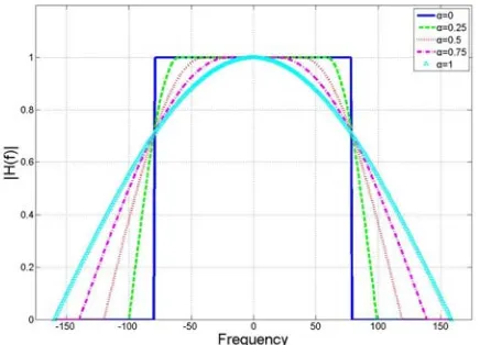
frequency response as shown in Eq. (1) with its associated plot as shown in Fig. 1-A.
otherwise M k M M k M M k k HT , 0 2 1 2 1 , 2 1 2 cos 2 1 0 , 1 ) ( (1)
Where M is the number of data symbols, k is the index of the discrete frequency component and α is the roll-off factor, has range from 0 to 1.
[image:2.595.64.282.298.455.2]From Fig. 1-A, it reveals that different filter responses will be generated when α varies and it also appears that higher α value will have wider filter bandwidth. Furthermore from filter time response, as shown in Fig. 1-B, the filter sidelobe levels vary when different α value is selected; consequently the system bit-error performance will also be affected. The resulting PAPR levels under various α values for various transmission systems have been simulated and will be presented in the sequel.
[image:2.595.76.281.478.635.2]Fig. 1-A. Square-root Raised Cosine Filter with Different Roll-off Factors.
Fig. 1-B. Time Response of the Square-root Raised Cosine Filter with Different Roll-off Factors.
B. System Functional Blocks
Three transmission system models with a maximum of five component carriers in each system modelare considered. Four modulation modes, QPSK, 16-QAM, 64-QAM, 256-QAM, are used for the transmitting signals.
The first transmission model is without spectral filter in each component carrier path as shown in Fig. 2. M modulated symbols at the modulator output in each component carrier path are passed through M-DFT module to generate their associated frequency domain symbols; they are then transmitted through the N- point IFFT module to generate the final time domain signal for each aggregated path. The number N used in the IFFT module depends on the number of component carriers aggregated in the system. And it has many possible arrangements in the N-IFFT module when M-DFT output signals from each component carriers are processed in the IFFT module. The time signals out of the N-FFT modules in each component carrier are then summed and transmitted through the transmitter antenna.
The second transmission model we consider has the structure as shown in Fig. 3 that has the same structure as the transmission model 1 except that it adds a Copy & Filter/Subcarrier Mapping module in each component carrier path before the M-DFT output signals entering into the N-IFFT module. The Copy & Filter operation includes data signals copy and filtering operation that the square-root raised cosine filter as discussed above is used as the filter in this operation.
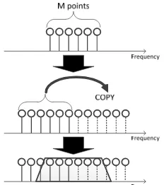
In the Copy operation it first gets a copy of the M data signals and then cascades the copied M data signals at the end of the original M data signals as shown in the middle plot of Fig. 4 [7]. Then the square-rooted raised cosine filter has its filtering operation onto the resulted cascaded 2M data signals.
CC1 Modulation M-DFT N-IFFT
CC3 Modulation M-DFT N-IFFT
CC4 Modulation M-DFT N-IFFT
CC5 Modulation M-DFT N-IFFT CC2 Modulation M-DFT N-IFFT
[image:3.595.108.488.49.298.2]Σ Tx
Fig. 2. Transmission System Model without Spectral Filter (Model 1).
Σ
CC1 Modulat ion M-DFT N-IFFT
CC2 Modulat ion M-DFT N-IFFT
CC3 Modulat ion M-DFT N-IFFT
CC4 Modulat ion M-DFT N-IFFT
CC5 Modulat ion M-DFT N-IFFT
Tx Copy & Filter
Sub-carrier mapping
Copy & Filter Sub-carrier mapping
Copy & Filter Sub-carrier mapping
Copy & Filter Sub-carrier mapping
Copy & Filter Sub-carrier mapping
Fig. 3. Transmission System Model with Spectral Filter (Model 2)
Σ
Phase randomization
TX N-IFFT
Copy & Filter Sub-carrier mapping
CC1 Modulation M-DFT
N-IFFT Copy & Filter
Sub-carrier mapping
CC2 Modulation M-DFT
N-IFFT Copy & Filter
Sub-carrier mapping
CC3 Modulation M-DFT
N-IFFT Copy & Filter
Sub-carrier mapping
CC4 Modulation M-DFT
N-IFFT Copy & Filter
Sub-carrier mapping
CC5 Modulation M-DFT
Fig. 5. Transmission System Model with Spectral Filter and Phase Randomization (Model 3).
Fig. 4. Copy & Filter/Subcarrier Mapping Process.
I. SIMULATION RESULTS
This section shows the simulated results of the resulting PAPR levels for each possible carrier aggregated transmission system. The system parameters used in the simulation are: M = 160, the number of data symbols considered in each component carrier path and N= 2048 is used in the N-IFFT module. The pre-assigned phase set for data symbols randomization has four elements 1+i, 1-i, -1+i and -1-i. The roll-off factor of the spectral filter varies from
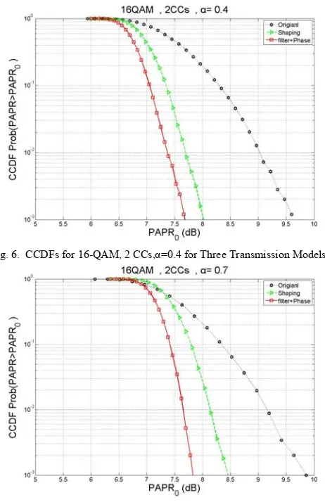
0 to 1 with step size of 0.1. Four modulation modes, QPSK, 16-QAM, 64-QAM, and 256-QAM are considered. The resulting complementary cumulative contribution function (CCDF) of PAPRs for each possible combination of system parameters for the three transmission system models are simulated and compared. We only present here the simulation results of using 16-QAM modulation, 2 component carrier (CC) paths with spectral filter roll-off factors α = 0.4 and α = 0.7. They have the results as shown in Fig. 6 and Fig. 7 for α = 0.4 and α = 0.7 respectively.
[image:3.595.114.230.512.643.2]Similarly for 16 QAM modulation with 5 CCs it has CCDF PAPR performances as shown in Fig. 8 and Fig. 9 for the situations whenα=0.2 andα=0.4 respectively. It has the best performance at α=0.2 and it starts the ‘cross-over’ situation when α=0.4.
[image:4.595.55.286.109.466.2]Fig. 6. CCDFs for 16-QAM, 2 CCs,α=0.4 for Three Transmission Models.
[image:4.595.59.283.114.271.2]Fig. 7. CCDFs for 16-QAM, 2 CCs,α=0.7 for Three Transmission Models.
[image:4.595.305.550.471.532.2]Fig. 8. CCDFs for 16-QAM, 5 CCs,α=0.2 for Three Transmission Models.
Fig. 9. CCDFs for 16-QAM, 5 CCs,α=0.4 for Three Transmission Models.
From simulation results it appears that with QPSK, 16-QAM, 64-16-QAM, and 256-QAM modulations when different number of CCs is considered in the aggregated system the CCDF PAPRs improve when α increases but when α reaches to certain level it starts the performance cross-over phenomena. This is due to the fact when α increases the effective spectral filter bandwidth widens and when α reaches certain level it does not have enough guard intervals among data symbols and the intersymbol interference introduced among data symbols by the sidelobe level of the filter will be increased. Table 1 lists the simulation results when different CCs are aggregated in the system with QPSK, 16-QAM, 64-QAM, and 256-QAM modulations; the α values when the system has the best CCDF PAPRs and the α values when the CCDF PAPRs starting revealing the cross-over situations.
Table I α Values when CCDF PAPRs Have Best Performances and when Cross-Over Phenomena Appears for Different CCs in the Aggregated
System and with Different Modulation Formats.
1CC 2CCs 3CCs 4CCs 5CCs
QPSK 0.5 0.5 0.5 0.4/0.8 0.3/0.6
16-QAM 0.5 0.4/0.7 0.3/0.5 0.3/0.4 0.2/0.4 64-QAM 0.5/1 0.4/0.6 0.3/0.4 0.3/0.4 0.2/0.4 256-QAM 0.4/1 0.4/0.6 0.3/0.4 0.2/0.4 0.2/0.4
From the results as listed in the table it reveals that when the number of CCs used in the system aggregation is given and when a modulation format is selected then we know what is the αvalue that will result in the best CCDF PAPR performance and what are αvalues cannot be selected since in this range the CCDF PAPRs performances will be deteriorated. And also when more CCs are aggregated in the system the less of αrange values can be used.
II. CONCLUSION
[image:4.595.60.283.492.655.2]deteriorating for each modulation format. Although we presented the phase randomization set with elements {1+i, 1-i, -1+i, -1-i} in this paper other phase randomization sets and their associated PAPR performances had also been considered. Furthermore with the transmitter modulator as proposed in this paper we are considering in the upcoming project to design its associated receiver structure so as to have the resulting system meet certain system performance criterion.
REFERENCES
[1] S. H. Han and J. H. Lee, “An Overview of Peak-to-Average Power Ratio Reduction Techniques for Multicarrier Transmission,” Wireless
Communications, IEEE, vol. 12, no. 2, April 2005, pp. 56-65.
[2] H. G. Myung, J. Lim, and D. J. Goodman, “Single Carrier FDMA for Uplink Wireless Transmission,” Vehicular Technology Magazine, IEEE, vol. 1, no. 3, Sept. 2006, pp. 30-38.
[3] Y. Akaiwa, Introduction to Digital Mobile Communication, 1st ed., 1997.
[4] S. Daumont, B. Rihawi, and Y. Lout, “Root-Raised Cosine Filter Influences on PAPR Distribution of Single Carrier Signals,” Proc.3rd International Symposium on Communications, Control and Signal
Processing (ISCCSP 2008), March 2008, pp. 841-845.
[5] S. Okuyama, K. Takeda, and F. Adachi, “MMSE Frequency-domain Equalization Using Spectrum Combining for Nyquist Filtered Broadband Single-Carrier Transmission,” Proc. IEEE 71st Vehicular
Technology Conference (VTC 2010-Spring), May 2010.
[6] S. B. Slimane, “Reducing the Peak-to-Average Power Ratio of OFDM Signals Through Precoding,” IEEE Transactions on Vehicular
Technology, vol. 56, no. 2, March 2007, pp. 686-695.
[7] A. Boonkajay et al., “Performance Evaluation of Low-PAPR Transmit Filter for Single-Carrier Transmission,” Asia-Pacific Conference on