TWEETHER Future Generation W-band Backhaul
and Access Network Technology
Claudio Paoloni
1, François Magne
2, Frédéric André
3, Xavier Begaud
4,Viktor Krozer
5, Marc Marilier
6,
Antonio Ramirez
7, José Raimundo Ruiz Carrasco
8, Ruth Vilar
8, Ralph Zimmerman
91Lancaster University, Lancaster LA1 4YW, UK
email: [email protected]
2When-AB, Paris, France
3Thales Electron Devices, Vélizy 78140, France
4LTCI, Télécom ParisTech, Université Paris-Saclay, France
5Goethe University of Frankfurt, Frankfurt 60323, Germany,
6OMMIC S.A.S., Limeil Brevannes 94453, France
7Fibernova Systems, Valencia 46022, Spain
8Universitat Politècnica de València, Valencia 46022, Spain,
9HF Systems Engineering GmbH, Kassel 34123, Germany
Abstract—Point to multipoint (PmP) distribution at millimeter wave is a frontier so far not yet crossed due to the formidable technological challenge that the high atmospheric attenuation poses. The transmission power at level of tens of Watts required at millimeter wave for a reference range of 1 km is not available by any commercial or laboratory solid state devices. However, the availability of PmP with multigigabit data rate is pivotal for the new high density small cell networks for 4G and 5G and to solve the digital divide in areas where fiber is not convenient or possible to be deployed. In this paper, the advancements of the novel approach proposed by the EU Horizon 2020 TWEETHER project to create the first and fastest outdoor W-band (92 – 95 GHz) PmP wireless network are described. For the first time a new generation W-band traveling wave tube high power amplifier is introduced in the transmission hub to provide the enabling power for a wide area distribution.
Keywords—milllimeter waves; TWT; access; backhaul; W-band; 5G; Point to multipoint
I.
I
NTRODUCTIONThe urgency of enabling people to be connected to internet every time and everywhere at very high data rate and the increasing demand of bandwidth-hungry services, such as High Definition TV (HDTV), videoconferencing, online games, IoT, and many others, are placing unprecedented strain on operators’ networks to deliver the required capacity [1 – 5].
Faced with this exponential increase in data traffic, the cellular network operators are confronted with a precarious situation: accommodate the ever-increasing traffic growth, yet reduce the costs and consequently increase average revenue per user. In this scenario, operators have started to upgrade their 3G cell sites to 4G e-Node Base Station and to deploy large number of small cells to supply sufficient capacity density and
high-quality contiguous and ubiquitous coverage. However, deploying large numbers of small cells helps to solve the capacity problem for the radio access network, but adds novel challenges for backhaul, with substantial impact on the costs. Such a backhaul problem on 4G small cells will indeed worsen with 5G, where density and capacity will be considerably increased (small cells of 100m radius, @ 2.4 GHz). This will lead to install a higher density of Points of Presences (PoP) to feed the small cells in the attempt to increase efficiency, reliability and consumption. The challenge is therefore to provide an affordable multi-gigabit backhaul solution that can allow flexible, scalable small cell deployments. A capacity density of Gbps/km2 class is required.
A second important aspect, with social implications, of internet distribution, is the digital divide due to the still low coverage by fast broadband internet access in most of the residential, sub urban or “rurban” areas, where the deployment of fiber is not convenient or feasible. This affects millions of households with poor Internet connections. Hopefully, 5G will introduce LTE @3.5GHz very suitable to offer high throughputs to houses. However, the current limitation in bandwidth and capacity of microwave wireless networks can only be overcome by the exploitation of unused portions of the spectrum at millimeter wave frequencies (above 30 GHz).
The total capacity requested today for the 4G plus WiFi small cells backhauling scenario is around 1 Gbps/km2. It is expected
that 5G will add a factor from 3 to 5 to the 4G capacity, meaning that in some dense areas it would rise to 10 Gbps/km2 with small
cell radius < 100m. In residential areas, the capacity could reach 1.5 Gbps/km² with larger cells (250m radius). In both cases, throughputs of a backhaul link would range from 50 to 200 Mbps per cell.
The TWEETHER project aims to respond to this challenge by a novel point to multipoint wireless system operating at W-band (92 – 95 GHz), to provide a capacity density up to 10 Gbps/km2. In this paper, the architecture and the key components of system, in advanced fabrication status, will be described [8].
II.
W-
BANDP
OINT TO MULTIPOINTW
IRELESS NETWORKA. Why Point to multipoint at W-band
The millimeter waves are unanimously considered the new frontier of wireless communications due to the wide availability of spectrum for multi-gigabit data rate [1 - 4]. The Q-band (40.5 – 43.5 GHz) [5] regulated for PtP and PmP, V-band, (59 – 64 GHz) and E-band (71-74 GHz, 81-85 GHz) [6, 7] both regulated for PtP, are already used for internet distribution. Millimeter wave PtP systems are available at V-band and E-band, based on the available low power solid state transmitters and high gain and directivity antennas (up to 50 dBi). PmP systems are available only at Q-band, with limited spectrum. PtP backhaul can be feasible only by using a high number of antennas at the transmission hub, with high cost of equipment, space and renting of the masts.
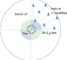
On the contrary, point to multipoint (PmP) backhaul is a more effective solution (Fig.1), due to the use of one low gain antenna at the transmission hub to feed a high number of PoPs. It is of easy installation, high flexibility and configurability and permits significant savings in TCO (Total Cost of Ownership) with up to 50 percent reduction in comparison to fibre [9, 10]. The W-band (92 – 95 GHz) is a portion of the spectrum still not exploited, that represents a very promising band for PmP deployments, due to 3 GHz available bandwidth, the traditional llight licensing for PmP, and the small footprint of the equipment made possible by the short wavelength
B. Capacity
The W-band offers almost 3 GHz (92 – 95 GHz) for high capacity wireless distribution. The system capacity is computed assuming an allocation of 1GHz per operator and a re-use frequency ratio 2. A sector would use 500 MHz in order to alternate sub-bands for frequency re-use and decoupling between sectors. This means that ten 40 MHz channels or five 80 MHz channels can be used or a mix of them, with 10 MHz of frequency guard separation between channels. With these
channel bandwidths, the modulation order will determine the maximum capacity over one link. In this sense, the modulation order should be limited to 64 QAM (256 QAM may be possible for very small cells at short distance) to obtain a Frame Loss Rate (FLR) under 10-6.
Therefore, for an allocation of 500MHz per sector and considering 64QAM ¾ modulation scheme, the capacity delivered as a function of the modem configuration can reach 1.35 Gbps.
The total capacity of one Transmission Hub (TH) will be therefore S*1.35 Gbps, being S the number of sectors. Depending on the configuration of the TH, for example with 4, 6 and 8 sectors, it is possible to deliver 5.4 Gbps, 8.1 Gbps and 10.8 Gbps respectively.
C. Coverage and range
Two main obstacles have so far prevented the development of millimeter waves PmP systems: one is the atmospheric attenuation under rain conditions, the second is the technology to provide sufficient output power to overcome the attenuation. An initial estimation of the output power needed at the transmitter for enabling a PmP at W-band was made assuming the budget link for a kilometer range and 10 terminals of 40MHz bandwidth each (e.g. considering 1GHz allocation for each operator, as explained in previous section). For this computation, a number of factors such as the absorption equations for rain intensities, including probabilities of intensities for a given ITU zone, and availabilities depending on range, antenna gains, noise figure, circuits losses, phase noise, C/N at transmission, correcting codes effect and yield of MAC layer, processing degradation depending of MSC (modem bandwidth and frequency guards, back-off, PAPR) and efficiency (FEC, MAC, IP) were considered. It has been assumed 99.95% availability.
[image:2.595.322.559.555.678.2]The rain attenuation is the most critical parameter that affects the range and the availability at millimeter waves. The EMEA (Europe, the Middle East and Africa) and the US the rain zones ITU, from A to K are considered as main TWEETHER scenario. In case of ITU zone E/ F, range in the order of 1 km is obtained with 64QAM and 720Mbps with 99.99% availability. In case of heavy rain, the availability at 99.99% is
Fig.1 Transmission Hub Sectors (radius R, capacity C, sector angle zz°.
[image:2.595.106.222.586.690.2]obtained by ACM with a lower modulation scheme (QPSK) reducing the capacity.
The calculation provides a linear output power of 10W at the Transmission Hub to enable the requested coverage. Due to the high order of the modulation scheme, high linearity is needed, imposing 6dB back-off. Finally, an amplifier with 40W saturated power is needed. This demonstrates the challenge of enabling a PmP system at W-band as no amplifiers are presently available to provide 40 W at W-band.
Fig. 2 reports the estimation of the area covered by the system, feeding up to tens of PoPs, for different cell radius and sector angles. This figure shows that, assuming a deployment of small cells with 100 m radius, a TH with four 90º sectors covers an area of 850 m radius, equivalent to 2.5 km². This scenario is suitable for high density cells. In case of larger cells, e.g. 200 m cell radius, a TH with 12 sectors (aperture angle 30°) can cover an area of about 27 km² and about 3 km radius.
This case is suitable to provide cost effective broadband access in residential or rurban areas. The decreasing of the sector angle leads to an increase in the range, underlying the versatility of the TWEETHER system given by the possibility to choose the number and the aperture angles of the sectors, depending on the coverage, with important and positive impact on the TCO.
D. TWEETHER system specifications and performance
The fabrication of equipment for PmP at W-band is a challenge. The low gain antennas for covering sectors in the range 30º - 90º requires transmission power of tens of Watt, presently not available by solid state power amplifiers [11] at these frequencies.
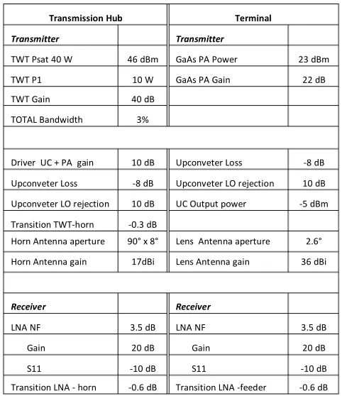
The H2020 TWEETHER project aims to the design, fabrication and test of the first W-band Point to multi point system. TWEETHER system specifications are reported in Table I. It is notable the high power that the TWT will provide, up to 40W saturated in W-band.
Each sector supports an end-to-end sub-network based on IEEE 802.3 aggregation, connectivity and switching standard protocols and with Gigabit Ethernet Interfaces. This sub-network comprises two elements, the Transmission Hub and the Network Terminal Equipment (NTE) (Fig. 3):
•The Transmission Hub (TH), connected to a fiber PoP, provides high aggregated capacity to feed several terminals.
The TH is composed of an Indoor Unit (IDU) dealing with the baseband and intermediate frequency communications. The IDU accommodates a stack of modems on separated channels, each dedicated to a PoP. The aggregation of these independent half-duplex TDD channels is multiplexed and sent to an Outdoor Unit (ODU), which is responsible for the up and down-conversion of the intermediate frequency channels to the 92 - 95 GHz frequencies radiated by the sector antennas integrated in this module.
•The NTE delivers basic Service Interfaces to customer’s Points of Presence (small cells or residential access PoPs). It establishes a single connectivity to the TH where they are connected through a VLAN. The NTE comprises
directive antennas, a transceiver for W-band up/down conversion and the IF modem.
Once the network architecture is defined, key aspects are the capacity provided by each sector, its coverage and how many PoPs will be connected in an area and at which ranges.
III.
W-
BANDE
NABLINGT
ECHNOLOGYPresently, no devices are available to provide the requested level of transmission power at W-band to enable the PmP as in Table I. The solid state electronic at W-band is progressing. State of the art high power solid state MMICs based on GaN provide power amplifiers with saturated power in the range of 30dBm [11].
The challenge of TWEETHER is to develop components suitable to build a transceiver for high capacity PmP system, operationally simple, with low TCO.
[image:3.595.312.553.64.343.2]The breakthrough of TWEETHER project is integrating a novel, compact, low cost and high yield Traveling Wave Tube (TWT) power amplifier with 40 W saturated output power, and
Fig.3 Sub-network layout
Transmission Hub Terminal
Transmitter Transmitter
TWT Psat 40 W 46 dBm GaAs PA Power 23 dBm
TWT P1 10 W GaAs PA Gain 22 dB
TWT Gain 40 dB
TOTAL Bandwidth 3%
Driver UC + PA gain 10 dB Upconveter Loss -8 dB
Upconveter Loss -8 dB Upconveter LO rejection 10 dB
Upconveter LO rejection 10 dB UC Output power -5 dBm
Transition TWT-horn -0.3 dB
Horn Antenna aperture 90° x 8° Lens Antenna aperture 2.6°
Horn Antenna gain 17dBi Lens Antenna gain 36 dBi
Receiver Receiver
LNA NF 3.5 dB LNA NF 3.5 dB
Gain 20 dB Gain 20 dB
S11 -10 dB S11 -10 dB
Transition LNA - horn -0.6 dB Transition LNA -feeder -0.6 dB
[image:3.595.313.549.542.618.2]
10 W at 1-dB compression point at the transmission hub, to power an affordable high performance transceiver, based on a novel GaAs MMIC chip-set at 92 - 95 GHz.
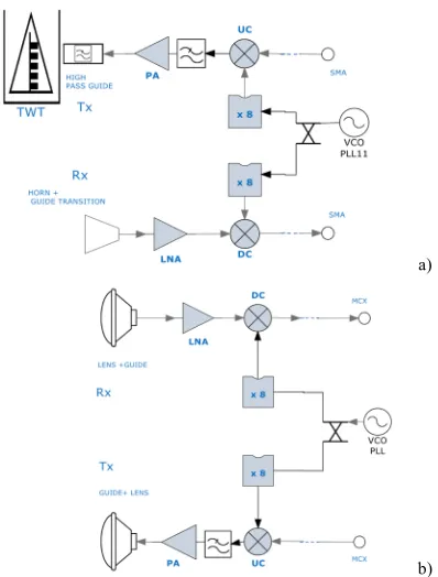
Regarding the radiation level, the use of a low gain antenna at the TH keeps the level below the ETSI and FCC limits. The schematics of the TWEETHER W-band system is shown in Fig.4. Transmission Hub (Fig. 4 (a)) and NTE (Fig. 4 (b)) use the same chipset.
A description the design and fabrication status for the various components is summarized in the following. The main system specifications are listed in Table I.
A. W-band Traveling Wave Tube
TWTs (Fig. 5a) are commonly used in specific, high end and high reliability applications where high power is needed. The maximum operating frequency of the commercial TWT is below 50 GHz due to the small dimensions that make challenging the fabrication and assembly at millimeter waves [12, 14]. At the W-band, the fabrication challenge is formidable due to the dimensions of the parts in the range of hundreds of microns. W-band TWTs are reported in literature only at laboratory level. A new approach has been adopted to make the fabrication easier and satisfy the system specifications [14]. A novel W-band TWT has been designed and is in advanced fabrication stage. The output power is higher than 40 Watt in the whole frequency range. In Fig.5a is shown the TWT cross section. The folded waveguide (FWG) is the interaction structure. The electron beam travels in the beam tunnel along the FWG and by interaction with the electric field in the FWG its energy is transferred to radiofrequency field. The electron gun and the magnetic focusing system must provide a well
confined electron beam. Both these parts have been fabricated and successfully tested.
The folded waveguide has been microfabricated in OFHC (Oxygen free high conductivity) copper [13]. The small section of the waveguide, 0.6 mm2, requires a high precision CNC
milling to be realized with tolerance better than 5 microns. A sample of the realized FWG is shown in Fig. 5b.
B. Multi-chip module assembly
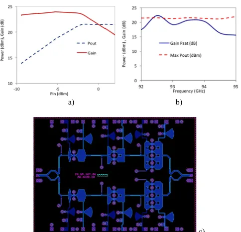
A purposely designed low power subassembly is under development for the TH and the NTE. It is based on a GaAs MMIC chip set with 100nm gate length, including 8X-multiplier, Power Amplifiers (PA) for the NTE (Fig.6), Low Noise Amplifier (Fig.7), Up and Down Converters and a Synthesizer. The specifications for the output power of the MMIC power amplifier are important to provide the required range to the NTE. The MMIC PA has been redesigned with the target of about 23 dBm in the frequency band, value at the state of the art in GaAs in Europe. All the chipset parts have been fabricated and measured with satisfactory results. The preliminary measurements provide a gain of 23 dB and an output power of 21.6 dBm (Fig. 6 a, b). Further improvements are in progress to increase the output power to extend the NTE range. The Low Noise amplifier provides less than 3dB of Noise Figure with 25 dB gain (Fig.7a). The LNA chip in the mount is shown in Fig.7b.
Low-phase noise LO signal generation is crucial for the required system performance. This is accomplished using a traditional low phase-noise synthesizer and a direct digital synthesizer ASIC in BiCMOS, both being currently tested. One of the challenges is a reliable assembly of the breadboard including the W-band and IF component and the transition to the TWT. A purposely designed subassembly approach is under development to reduce the interconnection losses.
a)
b)
Fig. 5 a) TWT cross section schematic with FWG and the electron beam, b) detail of the microfabricated copper FWG. To note the beam tunnel crossing the FWG.
a)
[image:4.595.85.284.67.329.2] [image:4.595.311.555.78.267.2]C. Antennas
In the framework of the TWEETHER project, two different antennas are required [15]. A pyramidal horn low gain antenna to cover a defined sector from the transmission hub (TH) has been adopted because of simplicity of its design and realization. The size of the aperture has been optimized to satisfy the
specification in Table I. High directive antennas are necessary for the NTE. The hyperbolic lens antenna has been chosen for its simple design and high gain. The simulation and measurements of the radiation patterns for the NTE antenna in the E and H planes at 92.5 GHz is given in Fig. 8. This result presents a high directive radiation pattern with a HPBW of 2 degrees in both planes without side lobes.
The lens profile focuses the energy up to ± 39 degrees and the gain is better than 38 dB over the required operating band. All the antennas have been fabricated and measured.
IV. CONCLUSIONS
The H2020 TWEETHER system represents a new concept of future generation network infrastructures for backhaul and access. It is a Point-to-multipoint wireless system operating at W-band, based on a novel TWT high-power amplifier. The system has been conceived to be implemented for 4G and 5G deployments in dense urban environments with a lower TCO compared to fiber-based or point-to-point-based backhauls.
The chipset and the TWT beam optics have been successfully tested. The integration of the parts is in progress.
R
EFERENCES[1] Z. Pi and F. Khan, "An introduction to millimeter-wave mobile broadband systems," in IEEE Comm. Magazine, pp. 101-107, June 2011.
[2] T.S. Rappaport et al., “ Millimeter Wave Mobile Communications for 5G Cellular: It will work!”, IEEE Access, pp. 335-349, Mai 2013.
[3] “Rethinking Small Cell Backhaul: A Business Case Analysis of Cost-Effective Small Cell Backhaul Network Solutions,” White paper by Wireless 20/20.
[4] H. Mehrpouyan, et al. "Hybrid millimeter-wave systems: a novel paradigm for hetnets," in IEEE Communications Magazine, vol. 53, pp. 216-221, January 2015
[5] R. Vilar, J. Martí and F. Magne, "Point to multipoint wireless backhaul systems for cost-effective small cell deployment," Microwave Conference (EuMC), 2015 European, Paris, 2015, pp. 1092-1095.
[6] D. Richardson, The Evolution & Economics of E-Band for Wireless Backhaul
,
http://www.wirelessdesignmag.com/print/articles/2014/05/evo lution-economics-e-band-wireless-backhaul[7] C. Colombo; M. Cirigliano "Next-generation access network: A wireless network using E-band Radio frequency (71–86 Ghz) to provide wideband connectivity" Bell Labs Technical Journal, vol.16, pp.187-205, June 2011 [8] TWEETHER website [Online]. Available: http://www.tweether.eu
[9] R. Taori et al., "Point-to-multipoint in-band mmwave backhaul for 5G networks," in IEEE Comm. Mag., pp. 195-201, January 2015.
[10] C. Paoloni, et al. “Millimeter wave wireless system based on point to multi-point transmissions.” EUCNC 2016, Athens, Greece.
[11] J. Schellenberg et al., "W-Band, Broadband 2W GaN MMIC," in IEEE MTT-S International Microwave Symposium (IMS), 2-7 June 2013 [12] C. K. Chong and W. L. Menninger, "Latest Advancements in High-Power
Millimeter-Wave Helix TWTs," IEEE Trans. on Plasma Science, vol.38, no.6, pp.1227,1238, June 2010
[13] S S Dhillon et al 2017, The 2017 terahertz science and technology roadmap J. Phys. D: Appl. Phys. 50 043001,
[14] C. Paoloni, F. Andre, S. Kohler, V. Krozer, TL Quang, R. Letizia, A. Sabaawi, G. Ulisse and R. Zimmerman, 'A traveling wave tube for 92 - 95 GHz band wireless applications' 41st Int. Conference on Infrafred, Millimeter and Terahertz Waves, IRMMWTHz, Denmark, 2016. [15] J.E. González, X. Begaud, B. Huyart, Q. T. Le, R. Zimmermann, F.
Magne ‘Millimeter Wave Antennas for Backhaul Networks’, EuCAP 2017, Paris, March 2017.
a) b)
[image:5.595.42.284.57.290.2]c)
Fig. 6 W-band power amplifier. a) Pout/Pin and Gain as a function of Pin, b) Saturated power and gain, c) layout
[image:5.595.51.280.326.479.2]
a) b)
Fig.7 Low Noise amplifier. a) Noise figure and b) photo of the LNA chip
[image:5.595.47.284.593.680.2]