© 2019, IRJET | Impact Factor value: 7.211 | ISO 9001:2008 Certified Journal
| Page 6890
Weight Optimization of API 6D 12”-150 Class Plug Valve Body by Finite
Element Analysis and Experimental Method
Akash Chandrakant Yadav
1, Prof. G. R. Kulkarni
2, Prof. A. M. Qureshi
31
M. Tech. (CAD/CAM/CAE), Department of Mechanical Engineering, KITCOEK, Kolhapur, Maharashtra, India
2Professor, Production Department, KITCOEK, Kolhapur, Maharashtra, India
3
Professor, Department of Mechanical Engineering, KITCOEK, Kolhapur, Maharashtra, India
---***---Abstract -
In the field of fluid transfer systems, variouscomponents are incorporated in the fluid transfer systems for efficient transfer of the fluids. Valve is a device that regulates, directs or controls the flow of a fluid by opening, closing, or partially obstructing various passage ways. Valves are used in a variety of contexts, including industrial, military, commercial, residential, and transport. With the wide range of applications hydraulic valves are globe valves, butterfly valves, ball valves, gate valves, plug valves, check valves and needle valves. Recent work was carried out for weight optimization of API 6D 12”-150 class plug valve body by finite element analysis and experimental method. The step by step modification in the valve body was made for reducing the weight by using FEA simulation. The stress analysis was carried out for analyzing the maximum stress regions in existing valve body. The ANSYS workbench software support was used to carry out the stress analysis. The experimental stress analysis was carried out for validating simulation results by standard test rig by applying fluid pressure and stress estimation by strain gauge. By reduction in wall and flange thickness and providing fillet by appropriate amount; nearly 6.4% weight reduction was achieved in the valve body.
Key Words: Plug valve, weight optimization, FEA
1. INTRODUCTION
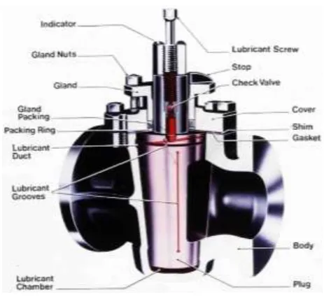
Plug valves are valves with cylindrical or conically tapered "plugs" which can be rotated inside the valve body to control flow through the valve. The plugs in plug valves have one or more hollow passageways going sideways through the plug, so that fluid can flow through the plug when the valve is open. Plug valves are simple and often economical. When the plug is conically tapered, the stem/handle is typically attached to the larger diameter end of the plug. Plug valves usually do not have bonnets but often have the end of the plug with the handle exposed or mostly exposed to the outside. In such cases, there is usually not much of a stem. The stem and handle often come in one piece, often a simple, approximately L-shaped handle attached to the end of the plug. The other end of the plug is often exposed to the outside of the valve too, but with a mechanism that retains the plug in the body.
Fig -1: Cross section of plug valve
The Accusable plug valve is a non-lubricated, resilient seal, plug type valve which has a mechanical means of freeing the plug before it is rotated from the closed to the open position. For Opening of plug valve, hand wheel has to turn counter clockwise. During this operation the plug is raised while the slips are retracted away from the body. When the slips are fully retracted from the body seating area, the plug is then able to rotate 90˚ to fully open position. When the valve is in the hill open position, slips and slip seals are completely protected from line flow. For closing of plug valve, hand wheel has to turn clockwise. During this operation the retracted plug and slips are rotated 90˚ without body contact. This rotation continues until the slips are positioned over the upstream and downstream port areas. Continued rotation of hand wheel mechanically forces the plug downward and forces the slips outward to seal firmly against the valve body. This produces a secondary metal to metal seal on both upstream and downstream areas providing double isolation. Biofuels Product isolation, Multi product manifolds, Custody transfer units, Tank farms (Oil Depots) Aviation fueling system are typical applications of plug valve.
[image:1.595.321.553.222.436.2]© 2019, IRJET | Impact Factor value: 7.211 | ISO 9001:2008 Certified Journal
| Page 6891
concentrated regions. The FEA was carried out for stressanalysis with the help of the ANSYS work bench software support and the experimental validation was carried out with the help of the strain gauge setup with standard valve testing setup.
2. LITERATURE REVIEW
Literature survey is carried out for getting the information regarding FEA and optimization techniques. This literature survey provided useful information regarding the experimental stress analysis method. The literature is collected from various international published papers, International journals and company documents. The literature review of work done by different researches in the area of weight optimization, FEA and experimental stress analysis technique is discussed below.
Mona Golbabaei et. al. [1] carried out work of centrifugal pumps engaged in high pressures must have smooth and safe operation without leakages. To control this phenomenon, optimal geometry and proper materials must be considered in design of all mechanical components including, significantly, the volute casing.
According to Deokar Vinayak Hindurao et. al [2].; in the field of competition, all companies should supply their goods and services with high quality, in shortest period with lower prices than its competitors in order to keep their capacity and power to compete.
Xue Guan Song et. al. [3] carried out work related to a butterfly valve is a type of flow control device, typically used to regulate fluid flow. This paper proposes a new process to meet desired needs in valve design that is characterized by the complex configuration.
A. Dorogoy et. al. [4] analyzed the errors inherent to the determination of mixed mode stress intensity factors from data obtained by using a three strain gauge rosette. The analysis shows that the errors are mainly due the third characteristic value (3/2) and its corresponding coefficients. It is also shown that the errors do not depend on the orientation angle of the rosette, the angle between the strain gauges and the material properties.
Aleksandar Petrovic [5] carried out stress analysis of a cylindrical pressure vessel loaded by axial and transverse forces on the free end of a nozzle. The nozzle is placed such that the axis of nozzle does not cross the axis of cylindrical shell. The method of finite element was applied to determine the state of stress in the cylindrical shell.
Dr. K. H. Jatkar et. al. [6] carried out FEA work on gate valves are used when a straight-line flow of fluid and minimum restriction is desired. Gate valves are so named because the part that either stops or allows How of fluid
through the valve acts somewhat like the opening or closing of a gate and is called, appropriately, the gate. The objective of this paper to perform a stress analysis of the critical component.
3. FINITE ELEMENT ANALYSIS
Simple mathematical model can be solved analytically, but more complex model requires use of numerical methods.
3.1 3D modeling of Valve Body
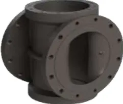
In ANSYS it’s very difficult to model the part with parametric modeling as compared with the available modeling software such as CATIA and Solid Works. To create a 3D model of valve body with all intricate geometric details, CATIA software is used. The created 3D model of valve body is as shown in fig 2.
Fig -2: 3D model of valve body
While creating 3D model care has been taken to model it with parametric expression, so as the dimensions changes it will reduce the repetitive time required for modeling. Small steps and champers are eliminated while modeling. The created 3D model is saved in part .iges tile format, as this file format is suitable during importing this model for meshing in ANSYS Workbench software.
3.2 Meshing of the 3D valve body model
In simple term meshing means connecting elements with each other. Elements are the building blocks of the finite element analysis.
[image:2.595.375.496.304.406.2] [image:2.595.333.538.586.740.2]© 2019, IRJET | Impact Factor value: 7.211 | ISO 9001:2008 Certified Journal
| Page 6892
Meshing is carried out by using ANSYS Workbench software.Model is meshed by using SOLID 45 element and with 7 element size. Total 1253416 elements and 1820087 nodes were created after meshing.
3.3 Material properties assigned
After completion of meshing material properties are assigned to meshed model. These properties listed below. Material used - ASTM A216 Grade WCC
Young‘s Modulus - 190000 N/ mm2 Poisons Ratio - 0.28
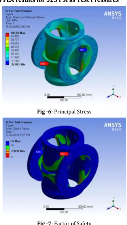
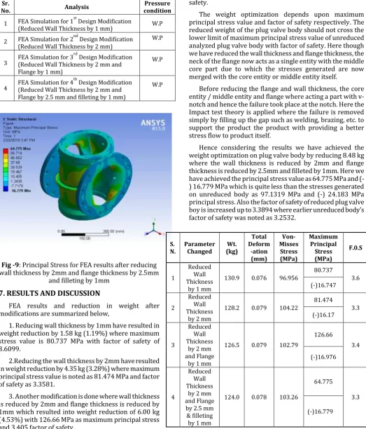
The maximum principal stress 97.319 MPa and (-) 24.183 MPa with 109.03 MPa and (-) 27.091 MPa founds in the rib at 290 PSI and 325 PSI as working pressures and test pressures as internal pressures respectively. As the internal pressure acts on the internal effective pressurizing area of valve body, results to expand the valve body. Ribs tries to hold the valve body in original position so ribs subjects to heavy tensile stress. As the internal pressure increases stresses in the valve body increases linearly.
3.4 FEA results for 290 PSI as Working Pressures
Fig -4: Principal Stress
Fig -5: Factor of Safety
3.5 FEA results for 325 PSI as Test Pressures
Fig -6: Principal Stress
Fig -7: Factor of Safety
3.6 Selection of locations for mounting strain gauge
rosettes
Finite element results shows that vertical rib is subjected to heavy tensile stress. But it is not possible to mount strain gauge rosette exactly on this rib, because thickness of rib is less for mounting of strain gauge rosette. For the convenience strain rosette will be mounted different portions of valve body. Three different locations decided by carefully analyzing the FEA results. Principal stress results from FEA will be compared with experimental stress results at the same point for validation of FEA results. Further to this, FEA and experimental stress analysis comparison will be useful to do reduction of the plug valve casting body.
[image:3.595.321.544.106.499.2] [image:3.595.55.270.376.707.2]© 2019, IRJET | Impact Factor value: 7.211 | ISO 9001:2008 Certified Journal
| Page 6893
Let us consider following abbreviations for the test andthe working pressure considered during the recent project work. Table 1 represents the FEA analysis results on actual component. Weight of part, total deformation, equivalent or Von Misses stresses, maximum principle stresses and factor of safety are mentioned in the table 1.
[image:4.595.306.563.446.562.2]W.P = Working Pressure T.P = Test Pressure
Table -1: FEA Analysis results on actual component
Sr. No. Parameters to Check Values
1 Weight of the part 132.57 kg
2 Total Deformation 0.085279 mm (W.P)
0.093214 mm (T.P)
3 Equivalent or Von-Misses Stress 95.291 MPa (W.P) 106.75 MPa (T.P)
4 Maximum Principal Stress 97.319 MPa (W.P)
109.03 MPa (T.P)
5 Factor of Safety 3.2532 (W.P)
1.9039 (T.P)
4. EXPERIMENTAL STRESS ANALYSIS
4.1 Experimental setup
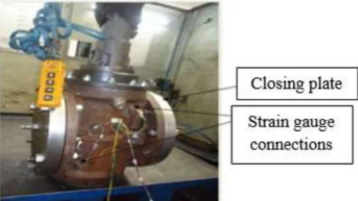
In this experimental work stain gauge technique is used to calculate stress at a point of interest. One opening made for fitting of relief valve kept open for the purpose of filling coolant in a valve body. Once the body totally filled with coolant that opening also make closed under standard pressure 325 Psi. One plug opening is provided to inlet closing plate, for connecting outlet pipe of the pressurizing unit. Testing has completed as per API 6D. After body test strain gauge rosettes are mounted on four locations which were decided previously by analyzing the FEA results. Strain readings are taken in two stages at 325 Psi. Strain developed in each arm of the rosette is noted from display of strain gauge indicator. The experimental setup is shown in the figure 8.
Fig -8: Experimental Setup
4.2 Experimental observations
For given load case the three readings are observed. The three readings are respective to the three axis of rosette namely 8a, 8b, and 8c. Safer getting the three axis readings lead wires of the respective directions are to be connected in the circuit to the meat panel of 10 channel balancing and switching unit along with strain indicator. The readings shown by strain indicator are in micro strains. Two sets of the readings are taken at given load conditions. Finally, the principal strains and principal stresses of the respective points of interest where rosettes mounted are calculated by analytical method. Table 2 showing the results.
5. COMPARISON BETWEEN FEA & EXPERIMENTAL
ANALYSIS
The values of deviation in principal stress, calculated based on experimental result and FEA results, for the valve body having wall thickness 19.5 mm and at same point where strain gauge rosettes was mounted. Results clearly show that the maximum deviation in these results is equals to 5.05 % which is allowed. While carrying the experimental validation the readings depends on environmental conditions like temperature difference, measuring instrument sensitivity, human errors, casting defects inbuilt while manufacturing valve body by casting these are some possible reasons for the deviation.
Table -2: Comparison between FEA & Experimental Analysis
Strain Gauge mounting
location number
Principal Stress (MPa)
% Error
FEA Results Experimental
Results
1 109.03 103.52 5.05
2 18.281 17.98 1.64
3 48.37 45.932 5.04
6. MODIFICATION OF THE VALVE BODY
As FEA and Experimental results are coming close to each other, different models of valve body by varying wall and rib thickness can be made. FEA of these models will be carried out without affecting original geometry as the 3D parametric modeling is built up in the CATIA. The FEA for modifications carried out in the model according to the industrial standards are shown in the table 3.
[image:4.595.37.292.593.736.2]© 2019, IRJET | Impact Factor value: 7.211 | ISO 9001:2008 Certified Journal
| Page 6894
Table -3: FEA for valve body modificationsSr.
No. Analysis conditionPressure
1 FEA Simulation for 1st Design Modification
(Reduced Wall Thickness by 1 mm) W.P
2 FEA Simulation for 2nd Design Modification (Reduced Wall Thickness by 2 mm)
W.P
3 FEA Simulation for 3
rd
Design Modification (Reduced Wall Thickness by 2 mm and Flange by 1 mm)
W.P
4 FEA Simulation for 4
th
Design Modification (Reduced Wall Thickness by 2 mm and Flange by 2.5 mm and filleting by 1 mm)
W.P
Fig -9: Principal Stress for FEA results after reducing wall thickness by 2mm and flange thickness by 2.5mm
and filleting by 1mm
7. RESULTS AND DISCUSSION
FEA results and reduction in weight after modifications are summarized below,
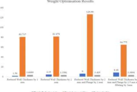
1. Reducing wall thickness by 1mm have resulted in weight reduction by 1.58 kg (1.19%) where maximum stress value is 80.737 MPa with factor of safety of 3.6099.
2.Reducing the wall thickness by 2mm have resulted in weight reduction by 4.35 kg (3.28%) where maximum principal stress value is noted as 81.474 MPa and factor of safety as 3.3581.
3. Another modification is done where wall thickness is reduced by 2mm and flange thickness is reduced by 1mm which resulted into weight reduction of 6.00 kg (4.53%) with 126.66 MPa as maximum principal stress and 3.405 factor of safety.
4. On making similar modification of reducing wall thickness by 2mm and flange by 2.5mm in thickness and
filleting by 1mm, the weight is reduced by 8.48 kg (6.40%) where 64.775 MPa as principal stress and 3.3894 as factor of safety.
The weight optimization depends upon maximum principal stress value and factor of safety respectively. The reduced weight of the plug valve body should not cross the lower limit of maximum principal stress value of unreduced analyzed plug valve body with factor of safety. Here though we have reduced the wall thickness and flange thickness, the neck of the flange now acts as a single entity with the middle core part due to which the stresses generated are now merged with the core entity or middle entity itself.
Before reducing the flange and wall thickness, the core entity / middle entity and flange where acting a part with v-notch and hence the failure took place at the v-notch. Here the Impact test theory is applied where the failure is removed simply by filling up the gap such as welding, brazing, etc. to support the product the product with providing a better stress flow to product itself.
Hence considering the results we have achieved the weight optimization on plug valve body by reducing 8.48 kg where the wall thickness is reduced by 2mm and flange thickness is reduced by 2.5mm and filleted by 1mm. Here we have achieved the principal stress value as 64.775 MPa and (-) 16.779 MPa which is quite less than the stresses generated on unreduced body as 97.1319 MPa and (-) 24.183 MPa principal stress. Also the factor of safety of reduced plug valve boy is increased up to 3.3894 where earlier unreduced body’s factor of safety was noted as 3.2532.
Table -4: Summarized results of modifications S.
N. Parameter Changed (kg) Wt.
Total Deform -ation (mm) Von-Misses Stress (MPa) Maximum Principal Stress (MPa) F.0.S 1 Reduced Wall Thickness
by 1 mm
130.9 0.076 96.956
80.737 3.6 (-)16.747 2 Reduced Wall Thickness
by 2 mm
128.2 0.079 104.22
81.474 3.3 (-)16.17 3 Reduced Wall Thickness
by 2 mm and Flange
by 1 mm
126.5 0.079 102.79
126.66 3.4 (-)16.976 4 Reduced Wall Thickness
by 2 mm and Flange
by 2.5 mm & filleting by 1 mm
124.0 0.078 103.26
64.775
3.3
[image:5.595.38.562.124.737.2]© 2019, IRJET | Impact Factor value: 7.211 | ISO 9001:2008 Certified Journal
| Page 6895
8. CONCLUSIONS
[image:6.595.41.278.259.418.2]In this dissertation work an attempt has made for weight optimization of plug valve body. Various models are created by changing the design parameters and analyzed these models for better results. Experimental structural strains and stresses measured by actual pressurizing the valve body, and compared it with FEA results. Strain gauge technique gives good results for the measurement of strain and stress at the point of interest. Following graph represents the overall results of the research work for four design modifications as shown in figure 10.
Fig -10: Weight optimization results
1. Results of finite element method for the structural analysis of the plug valve body are well in agreement with experimental results, as the deviation is maximum deviation is up to 5.05 % while allowable deviation is up to 7 %.
2. Eight new different optimized models created by changing the design parameters and analyzed .As there is restriction to change the flange dimensions, wall body thickness and neck dimensions are considered for optimization.
3. Results of decreasing the wall thickness and increasing the neck size are better than only reducing the wall thickness.
4. The best modified model is that, in which wall thickness is reduced wall thickness by 2 mm and flange thickness by 2.5mm and filleting by 1mm have reduces 8.48 kg (6.40 %) weight, because maximum stress level is much lower than the yield stress value of the material. FEA results for this optimized model shows that stresses in ribs also decreased because of increased rib thickness.
REFERENCES
[1] Mona Golbubaei. Rouhollah’l‘orabi, Ahmad Nourbakhsh,
KaroScdighianI, "Failure Detection and Optimizaaon of a Centrifiagal-pump Volume Casmg"Proceedings of the SEM Annual Conference June 1-4, 2009, Albuquerque
New Mexico USA, Society for Experimental Mechanics 1nc.
[2] DeokarVinayakHindurao. D. S. Chavan, “Optimization of
16” Plug Valve Body Using FEA And Experimental Stress Analysis Method", 1ntemational Journal of Mechanical Engineering, Vol. No. 1, pp. 79-86.
[3] Xue Guan Song, Lin Wang. SeokHeumBack, Young Chul
Park “Multidisctplinary optimization of a butteryly valve”, ISA Transactions, 2009, pp. 370-377.
[4] A. Dorogoy, D. Rittel, “0ptimum location of a (knee strain
gauge rosette for measuring mixed mode stress intensity factors ", Engineering Fracture Mechanics, 2008, pp. 4127-4139.
[5] AleksandarPetrovic,"Sn'ess Anubisw of Cylindrical
Pressure Vessels with Loads Applied to the Free End of Nozzle", International Joumal of Prmcsurc Vessels and Piping, 2001, pp. 485-493.
[6] K. H. Jatkar, Sunil S. Dhanwe,“Dynamic Analysis of