Decision
Data
Computer
Corporation
A Decision Industries Company
PN 24447-00
J I
3496 Workstation
User Reference
Manua~
1 Introduction
The CRT ... 1-2 The Smart T Connector ... 1-6 The Keyboard ... 1-7 The Logic Module ... 1-8 The Cartridge ... 1-9 2 Unpacking and Installing Your Workstation
Connecting the Modules ... 2-2 Installing the Cartridge ... 2-5 Initial Start-Up ... 2-6 Off-Line SetUp for Printer Default Parameter ... 2-10 Configuring the Workstation on the Host System ... 2-13 3 SetUp
Display Intensity ... 3-2 Display Contrast ... 3-3 Auto Dim ... 3-3 Reverse Image ... 3-4 Keyboard Clicker On/Off ... 3-4 Blink/Normal Cursor ... 3-5 Alternate Cursor ... 3-5 Extended Display ... 3-6 Language Character Set ... 3-6 Cursor Location indicator ... 3-7 MUltinational Character Set. ... 3-7 Keyboard ID ... 3-8 Set Address ... 3-8 4 Control Key Functions
Control Key Functions for the 122 key Keyboard ... 4-1 Control Key Functions for the 102 key Keyboard ... 4-7 5 Record/Playback Keys
ii
6 Fault Isolation Procedures
Pathway A ..•...•...•••...••....• 6-2 Power Test ...•...•...••..•...•... 6-3 Pathway B ...•....•..•...••..•.•... 6-4 Pathway C ...•...•...•.•...•...• 6-8 Pathway 0 ... 6-9 Mechanism Test ... , ... " .•.. , ... '" ....•.• " . 6-19 Sample Printouts and Switch Settings .•...•.... 6-20 7 Printer Control
System Addressable Printer ...•...• 7-1 Printer Status Indicators ...•... 7-2 Printer Control Menu ... 7-3 Printer Parameters Screen ... 7-4 Differences From IBM 5256 Operations ... 7-8 Differences From IBM 5224/5225 Operations ... 7-10 Appendix A - Error Codes
Appendix B - Diagnostics
Power-On Diagnostics ... B-1 Off-Line Tests ... B-1
This equipment generates, uses, and can radiate radio frequency energy and if not installed and used in accordance with the instruction manual, may cause interference to radio communications. It has been tested and found to comply with the limits for a Class A computing device pursuant to
Subpart J of Part 15 of FCC Rules, which are designed to provide reasonable protection against such interference in which case the user at his own expense will be required to take whatever measures may be required to correct the interference.
The policy of Decision Data is one of continuous development and improvement of its products and services, and the right is therefore reserved to alter the information contained in this document without notice. Decision Data makes every effort to ensure the accuracy of this document but does not accept liability for any error or omission. All steps, procedures, configurations, items, figures or instructions
referenced in this document are researched and checked to ensure the highest degree of accuracy and latest revision level of every item as it was available at the time of publication. Wherever practicable, Decision Data is willing to verify upon request the accuracy of any specific matter contained in this document.
Introduction
The Decision Data 3496 Workstation has five basic modules: The
Introduction
The CRT
Features
1-2
Your 3496 is equipped with a low-glare 12-inch screen in either amber or green. The angle of the display screen can also be adjusted by tilting the monitor up or down, or from left to right. An optional sunflex filter is available to reduce glare and improve the display contrast.
The power switch and the security keylock are located to the rear on the right side of the
CRT.
When the Workstation is locked, the terminal can be turned on, but cannot access the host. This allows the flexibility of changing operational characteristics in theDisplay
There are a variety of display characteristics that can be selected or changed by the user. All adjustments to the display are
controlled during SetUp mode by the Command keys. The display intensity and contrast can be increased or decreased. Characters can be shown on a dark background, or in reversed image as dark images on a light background.· The cursor can be displayed as blinking or steady, and can be an underscore or a solid block. The cursor location indicator can be displayed on the Status Line or can be turned off. The screen can auto dim automatically after 10 minutes unattended and can be recalled by pressing the Reset key. At sign-on the display is controlled by the host system. The
screen displays messages from the host system. If the spacebar is held down during power on the Offline screen appears on the display.
'
-~
--.
cAl'C~-cu,: ....
--
- c o• r , ~ ; • I
...
...
....
--Wil Wil Wil IMlca.. :11-':.
=-....
:--Scan oct ~ : ....
c.a. .... Iru ....
...
....
....
--Wil Wil IMl IMlSaL . . ~~ ta1.aa.a
ItGil "... '#1..00
I .... '
I:::::
:l
Ii
!.ann . . · •• eu. , .. ~v.
t... ...
:..a,
....
,
i . . . . 1
S
MoW
IMlI
IMlI
With the 83-key keyboard the choices on the Offline screen are accessed as follows:
Select
< Err-C> < Err-S>
Introduction
The screen will display an 80-column format. In this format. up to 24 lines of data can be displayed in the data area of the screen. At the bottom of the screen is a Status Line which displays mode and status indicators. The Record/Playback and printer prompts and messages will temporarily overlay some of the status line. A list of the Status Line indicators follows for your reference.
If you are in Extended Display (see Set Up), the terminal
emulation, terminal address, printer address, keyboard 10. language code, line parity error counter, and keyboard error counter are also displayed.
Normal Status Line Indicators
SYS
System Available-indicates that the host system is operating and available, and that the Workstation can access the host system.MSG
Message Waiting-indicates that a message is waiting for you on the host system.INH
Input Inhibited-indicates that the host system is processing your data and further input cannot be accepted; also occurs when the host recognizes an error condition.LCK
Key Lock-indicates that the Workstation is locked; the workstation is operational in Off-Line mode only.NV,U,K,KT,KL,L
Hardware Error Code Indicator-indicates hardware and NVRAM errorconditions.
0000
Error Code-indicates all operator errors that occur while communicating with the host or while the Workstation is offline.SHF
Shift-indicates that the Shift key or the Caps Lock key is depressed.INS
Insert-indicates that the Workstation is in the insert mode.D 1M
Dim-indicates that the display has turned itself off after 10 minutes with no user or system interaction; display returns to normal at first keystroke (Reset key recommended).M
Mode-indicates the current mode of the Workstation.PRT, STP
Printer Attention-indicates that the printer needs attention or the printer is not "ready."RR1CC
Row/Column Indicator-indicates the row and column position of the cursor.S
R
p
T
Setup-indicates that the Workstation is in Setup mode.
Record-indicates that the Workstation is in Record mode. While this indicator is displayed every keystroke is recorded.
I
Playback-indicates that the Workstation is in the Playback mode; characters and commands stored on one of the Record/Playback keys can be entered into the data area of the screen.
Test-indicates that the Workstation is in Test mode.
Extended Display Status Line Indicators
0000
o
o
o
00
000
000
Terminal Emulation-indicates the current terminal emulation. Terminal Address-indicates the station address of the terminal. Printer Address-indicates address for the printer emulation. Language-indicates either the multinational set or the language selected commands stored on one of the Record/Playback keys can be entered into the data area of the screen. Keyboard ID-indicates the workstation's keyboard 10.
Keyboard Error Count-indicates the number of keyboard errors since the workstation was powered on.
Introduction
The Smart T Connector
The smart T connector can be disconnected from the logic module so
that the workstation itself can be moved. The operation of devices attached to the "smart Til will not be affected by the removal of the workstation.
The Keyboard
1-6
Your Workstation comes with an 83, 102, or 122-key keyboard. The 122-key keyboard features a center cluster of keys in a standard
typewriter-style arrangement. On the far right of the keyboard is a numeric keypad. Control keys are located in two groups to the left and right of the center cluster (for a description of the functions of these keys, see Control Key Functions). Above the center cluster are 24 single stroke Command keys. The keyboard tilt angle on the 122-key
keyboard can be adjusted with the button underneath the upper center of the keyboard. While holding the button in, raise or lower the top edge of the keyboard. Release the button when the keyboard is at the most comfortable position for you.
The 102-key keyboard features a center cluster of keys set up in a standard typewriter arrangement. The function keys at the top of the keyboard are used as the Command keys. The Control keys are to the left of the center cluster and a numeric keypad is at the far left.
Both the 83-and 102-key keyboards can either lie flat or be set at an angle. The 1 02-key version can be adjusted by pressing the buttons on both sides of the top of the keyboard. The 83-key keyboard can be adjusted with a button underneath the upper center of the keyboard.
Introduction
The Logic Module
The logic module is a separate element of the Workstation. It has a raised receptacle on its top to secure the positioning of the
workstation monitor. There are connectors on the rear of the logic module for the keyboard, the CRT cable, the printer, and a Twinax connector to attach the "smart T" connector.
The door on the left side of the logic module opens to accept the system software cartridge.
There is a printer connector on the rear of the logic module.
The Cartridge
The cartridge plugs into the left side of the logic module in a
The Cartridge
Unpacking and Installing Your Workstation
Your 3496 is shipped in five modules (CRT, logic module, the "smart Til connector, cartridge, and keyboard). We recommend that you save the packing materia. after unpacking the Workstation. On-site replacement is available through Decision Data Service Incorporated; other maintenance options may require you to repack and ship problem modules back to DDS!. Follow all instructions in the User Reference Manual when installing the 3496.
If you encounter any problems when installing or operating the Workstation, contact OOCC Marketing Support (1-800-231-3322 or 215-674-3300 in PA).
Unpacking and
Installing
Connecting the Modules
1
Remove the CRT from its shipping package and place it on the desk or tabletop you will use as a workspace. When moving the CRT. lift it from undemeath the housing.2
Check that the security keys are enclosed with the CRT. Write down the key number and save it in a safe place.3
Remove the logic module from its carton and place it on the surface you will use as a workspace.4
Open the keyboard package. The keyboard shipping package contains the keyboard and the plastic overlay for the command keys.5
Slide the monitor base into the raised receptade on the logic module., I
7
P,lug ltbe keyboard cable~nto
ltbe 'baS9 of'tbe CRT. The 5-pin keyboard CQnnectotis at the :rear
'Irert.
I8
Hoild the Smart-1T" oormeCtoT byti\e .oord end IIn_ ihat the sheU of the ;connector slides up and down the 'ODnneamr about a quarterti an mch). Pull the shell back to expose ,tbe end of the connector~.
.---U
ru
~
IUIUI
O~~:
9
The Twinaxsocket ,on the WmTkstation has ,a 'key inside the ,tigbt hand side. Align tbe slot in fhecorme.ctorplug withthtekey and push the connector all the way onto the socket and screwitheshelhmnt01he sockeUhreads. If there is no cable attached to the "smart Til output, :theoutput connector ,automatically terminates.10
AttaohttbepoweriCDrdlttil,tI:Je rearofthe ·CRT.Make sure the workstation is powered off. Before plu.g;ging the powarcordinto the waJl ''Gutlet. be sure that the outlet is properly wired and grol:Jm4adusin.ga!hreB"!prongrece,ptacle.11
Your Workstation.comes with three numbered labels. One of these I abets should be applied to·1lte :maC'k..ofthetnonitor.,the ;bottom of the keyboard, and the bottom of the logic module for your sen/ice warranty to be valid.Installing the Cartridge
1
Open the cartridge door on the left side of the logic module.2
Slide the cartridge into the slot at the left side rear of the CRT base. Make sure that the cartridge label is facing up and that the'cartridge is firmly seated in the slot.UlIpaddDg
and
IDStalli~gInitial Start-Up- Workstation
1
il.Jn!loCk~
CRT w,ith the security key in the keylock at'tihe right rear of the mon'im~ bdd dc:Nm . . ~ bar, andtum
on the power. The Workstation takes about lIB secBDds to·warm '~ make sure you hold the space bar down. If the message",NV" ~
on
lIhe statusline.
press the Reset key. The Off-Une dispJay will ~~ ilfum ~ appealS" tum the Workstation off and check all connections. Ohe'dkllbBt1m iQRTijs un'lodked (thaUheslotis ,in the horizontal position). Then,Urn ate ~ om again 'm d!eck for the P,ower On display.
2
1f'he~icn
idreeiice <ad'mess, the language set, the terminal emulation (on the 12~amd l;G2Gyk~tm.ards).and the keyboard 10 should be set before connecting to·:tf:leiImSt
{EWiItlIlIta834e,
lheyboafd you must set the device address).FIrst,
turn offlla ~ion.lP.1ess
,mown
and hold the space bar on the keyboard, and turn on thelfllllldl"a:pin. iHlQldi!lm~ bar down until the Off·Une display appears. (Ifthe;emmSQl1:3iis lI~:pll8SS1!he'Error Reset key.) The Workstation will be in
Off~Lir!re 11i1Ulde.
3 ,
..
1ftI b iI:22Gyandttll2-4<ey :keyboards, select the terminal emulation to be used, pr:i!R tIIna rMIDde and IE 'kep. "Withthe~ykeyboard the terminal emulation isalJlclm:ldaII;rMt:to52!H-2. 11he,foUowingscr:een will be displayed:
Selecttemnir:ral emulations
<D>
.Exit
4
Press option 0 to exittha Terminal Emulation Selection. The Off-Une Display will appear again.5
To set the channel address, language set or multinational character set. or keyboard 10, press the SetUp key with the 122-key keyboard. the Shift and SetUp keys with the 102-key keyboard, or the Error Reset and S keys on the 83-key keyboard. A blinking"s"
will appear on the Status Une at the bottom of the screen. The device address number will be displayed as a number from 0 to 7, the language set will bedisplayed as 0-9 or A-C and the Multinational Character Set as a M. The keyboard 10 will normally be displayed as two dashes, or 00 through 63 with the 122-key keyboard or 00 through 31 with the 102-key keyboard. There is no display for the 83-key keyboard.
6
The channel address (0 to 7) on the Status Une increases each time you press the Set Address key. Your System Operator will determine your channel address number (7 is not a valid address and cannot be selected by using this key). If the address displayed is not the address you want, you can change it according to the keyboard you are using:Keyboard type Key sequence 122-key Command key 24 102-key Shift and F12 keys 83-key Shift and
=
keys7
The keyboard 10 number (- - and 00 to 63 on the 122-key keyboard and 00 to 31 on the 102-key keyboard) on the Status Une increases each time you press the Keyboard 10 key. The S3-key keyboard does not require a keyboard 10. The normal and default setting is twodashes, unless your System Operator assigns another number. If the keyboard 10 displayed is not the 10 you want, you can change it according to the keyboard you are using:
Keyboard type Key sequence 122-key Command key 23 102-key Shift and F11 keys 83-key N/A
Unpacking ,and Installing
Choose the language setrrom the chart below.
Language Character Message
Set Set Language
0 US/Canadian English
1 Belgian English
2 French French
3 French Canadian French
4 German/Austrian German
5
Italian Italian6 Norwegian/Danish English
7 Spanish Spanish
8 Spanish Speaking Spanish
9 UK English
A Swedish/Finnish Swedish B Brazilian English C Portugese English
9
The Multinational Character Set key enables the multinational character set. The selection of this set is indicated in the language field on the status line.When you choose the Multinational Character set it overrides any other language set choice but will not ovemCie the selected message language.
Keyboard type Key sequence 122-key Command key 22 102-key Shift and F10 keys 83-key Shift and 0 keys
10
When completed, press the SetUp key (or Error Reset and S keys on the 83-key keyboard) again to exit the SetUp mode and power off the workstation or continue to the next section.Off-Line SetUp for Printer Default Parameter
1
In order to set the default Print Format Parameters for the System Addressed Printer Capability, your Workstation must be off line and you can choose from the following selections: Select <Alt Cancel> <Setup> <AltTest> <Mode Print> <Mode E>Exit to ONLINE Configure Terminal Start OFf Une Tests Configure Printer
Select Terminal Emulation With the 83-key keyboard the choices on the Offline screen are accessed as follows:
Select
<Err- C> <Err- S> <Err- T> <Err - Print>
Exit to ONLINE Configure Terminal Start Off Une Tests Configure Printer
2
Press the Mode and the Print keys (or the Error Reset and Print keys with the 83-key keyboard). The Printer Configuration Display appears as shown below:PRINTER CONFIGURATION Select printer configuration:
<0> Exit
<1> Une Spacing <2> Font
<3> Character Spacing <4> Override Host <5> Character Set <6> Emulation <7> Address <8> Buffer
<9> Select Attached Printer
6 LPI 8 LPI Draft NLQ
10 CPI 12 CPI Compressed On Off
0123456789ABC 5256-3 5224-2 5225-4 01234567
Unpacking and Installing
Initial Power-On Printer Defaults
Printer default settings can either be changed permanently through the Printer Configuration Display in the Off-Une SetUp mode or temporarily through the printer's operator control panel. Parameters set through the Printer Control screen are stored in the Workstation's memory. When the Workstation is turned off and on again, the Printer Control screen parameters will be the last ones used. The following parameters are preset for your printer:
Parameter
Setting
Une Spacing 6 Unes per Inch
Font Draft
Character Spacing 10 CPt Override Host Off
Language Set
o
(US/Canadian English) Emulation IBM 5225-4Address 7*
Buffer Large
*If the Printer Device Address is 7 an error message is displayed if Mode Print is pressed while on line.
3
Repeatedly pressing an option number causes the select bar to move through the available choices for that option. Once the desired feature is highlighted, choose another option by pressing its corresponding number or press 0 to exit the Printer Configuration. The options are described below:Option
<0> Exit
<1> Une Spacing <2> Font
<3> Character Spacing <4> Override Host
2-10
Function
Returns you to the Off-Une screen.
Select 6 LPI,
a
LPI or host selected LPI for the desired line spacing.Select Draft or NLQ to change the character quality. Select 10 CPI, 12 CPI or Compressed for the desired
character spacing.
The printer's CPI can be designated as follows:
o Host Format Control: The CPI of the output will be set according to the information provided by the host.
<5> Character Set
<6> Emulation
<7> Printer Device Address <8> Buffer
The printer's character set can be made to correspond to that of the terminal. See the Language chart on page 2-8 for valid values. Select a number from 0-9; A, B, C or M to choose another language set. Several IBM printers can be emulated. Select 5256,
5224 or 5225 for the desired printer emulation. Note: The host must be configured to recognize the same printer type.
Select a number (0-7) for the desired address.
(7 disables the printer feature.)
Printing can be performed using a print buffer of the same size as that of the IBM 5256 printer. A larger burst mode buffer can be used to achieve slightly faster printing.
Select Large or Small for the desired buffer type. If you press any keys other than those displayed on the Printer Configuration
Display, the Invalid Setup Key error message (9013) will be displayed. To correct this error, simply press a valid key.
4
The last selection from the Printer Configuration screen allows you to select the attached printer. When you select 9 from the Printer Configuration screen you will see the following menu:ATTACHED PRINTER SELECTION Select Attached Printer:
<0>
Exit
<1> DDCC 651X <2> Proprinter XL <3> Epson FX -286 <4> Basic ASCII
Unpacking and Installing
Configuring the Workstation on the Host System
System/36
System/38
2-12
On System/36 systems, set the workstation emulation and address and perform an IPL with the workstation powered on. The system will automatically
recognize the workstation. Consult the IBM manual, "Operating Your Computer" SC21-9026 for directions on performing an IPL
The chart below shows the device code and the keyboard type for 3196 and 5291 emulations for reference, if the GNFIGSSP procedure is used.
Device Type 3196 5291
No. of Keys 102 122 83,102,122 on Keyboard
Device Code 15 15 10
Keyboard Type Enhanced 5250 Style 5250 Style The 83-key keyboard emulates a 5291 only.
When the workstation is configured on a System/38, consult the IBM System/38 Guide to Program Product Installation and Device Configuration, GC21-7775.
The 3496 Workstation can be configured as a 3196 or 5291 depending on the terminal emulation selected. Reference the chart below to determine the device type, model, and wsckbd parameters.
Device Type 3196 5291
No. of Keys 102* 122 83,102,
on Keyboard & 122
Screen Color Amber Green Amber Green n/a
Model B2 A2 B1 A1 n/a
WSCKBD GUSB GUSB PUSB PUSB TUSB
*
When installing a 3496 Workstation configuration as a 3196 with a102-key keyboard locally on a System/38, the workStation must be configured to a workstation controller-extended (WSCE).
Configuring the Workstation on the Host System
System/36
On System/36 systems, set the workstation emulation and run the CONFIG procedure.
System/38
When the workstation is configured as a 5292-01, consult the IBM System/38 Guide to Program Product Installation and Device Configuration, GC21-7775. Set the DEVTYPE for 3196 or 5291.
Set the MODEL and the WSCKBD according to the chart below: 102 122
SetUp
There are a number of operational characteristics, such as the brightness of the display or the cursor type, that you can adjust according to your preference. These adjustments are made by entering the SetUp mode. SetUp can be entered either on-line (after the power-on diagnostics are completed and the Workstation has communicated with the host) or off-line. There are a few operational characteristics that can only be changed off-line. • To enter SetUp mode off-line, press the space bar and hold it
down while turning on the Workstation. Hold the key down until the Off-Une dispk" appears. Then press the SetUp key with the 122-key keyboard, the Shift and SetUp keys with the 102-key keyboard, or the Error Reset and S keys with the S3-key keyboard.
• To enter SetUp mode on-line, press the SetUp key with the 122-key keyboard, the Shift and SetUp keys with the 102-key keyboard, or the Error Reset and S keys with the S3-key keyboard.
• Follow the instructions below for setting operational characteristics.
• To store your new settings and exit the SetUp mode, press the SetUp key or key sequence· a second time.
An explanation of each of the options on the SetUp menu is provided below.
An "S" in the Status Une indicates that you are in SetUp mode. Once in SetUp mode, all operational characteristics are changed by selecting the appropriate Command keys. Some options, such as display intensity or contrast, are adjustable over a wide range; their setup keys are auto-repeat keys. The keyboard clicker will click as you hold these keys down. More than one operational characteristic may be changed while in the SetUp mode.
SetUp
Display Intensity
Display Contrast
Auto-Dim
3-2
The intensity of the screen display is adjustable over a range of 16 steps. Once you reach the top limit of this feature the next choice will be the bottom again. You can reverse the order of the option by pressing the Alt key and Command key 1 simultaneously. This key is an auto-repeat key.
Keyboard type Key sequence 122-key Command key 1 102-key F1 key
83-key 1 key
The contrast of the screen display is adjustable over a range of 8 steps. Once you reach the top choice of this feature the next choice will be the bottom again. You can reverse the order of the option by pressing the Alt key and Command key 2 simultaneously. This key is an auto-repeat key.
Keyboard type Key sequence 122-key Command key 2 102-key F2key
83-key 2 key
The auto-dim feature protects your CRT screen from phosphor bum. When auto-dim is active, the screen automatically goes blank if there is no keyboard input or host system command input for 10 minutes. "DIM" appears in the Status Une to indicate that the screen has
auto-dimmed. The display returns to normal at the first keystroke (use Reset to restore the display). The dim indicator is enabled during SetUp. This key is an auto-repeat key.
Keyboard type Key sequence 122-key Command key 3 102-key F3key
Reverse Image
Alarm Duration
Keyboard Clicker On/OtT
Biink/Normal Cursor
The image on the display screen can be either green (or amber) characters on a dark background or reverse image, that is. dark letters on a light background.
Keyboard type Key sequence 122-key Command key 4 102-key F4key
S3-key 4 key
The duration of the alarm can be adjusted between .5 second. 1 second. or 1.5 second. The alarm sounds for the selected duration each time the key is pressed. The power on default is 1 second.
Keyboard type Key sequence 122-key Command key 5 102-key F5key
83-key 5 key
The keyboard clicker can be turned off entirely. Keyboard type Key sequence 122-key Command key S 102-key FSkey
Sa-key Skey
The display cursor can be either blinking or normal. Keyboard type Key sequence 122-key Command key 7 102-key F7key
SetUp
Alternate Cursor
The cursor type can be either an underline or a solid block.Keyboard type Key sequence 122-key Command key B 102-key FBkey
83-key Bkey
Extended Display
When extended display is activated, formatting is shown in hexadecimal code.Keyboard type Key sequence 122-key Command key 9 102-key F9key
83-key 9 key
Language Character Set
The terminal character option selects the character set tobe displayed. This option can only
be
activated in the Off-Une mode. A value of 0 stands for US/Canadian English. 3 stands for French Canadian. (See the section 2 for a listing of aI/language choices). This key is an auto-repeat key.Keyboard type Key sequence 122-key Command key 10 102-key F10 key
83-key
o
keyCursor Location Indicator
The location of the cursor on the screen (row, column) canbe
displayed in the lower left hand comer, or it can be turned off.Keyboard type Key sequence 122-key Command key 11 102-key F11 key
83-key -key
Multinational Character Set
The multinational character set option reassigns certain keys to display different characters. The character set can only be activated in the Off-Une mode. An "M" on the Status Une indicates that the multinational character set is chosen and active.Keyboard ID
Set Address
Keyboard type Key sequence 122-key Command key 22 102-key Shift and F10 keys 83-key Shift and 0 keys Keyboard ID can only be set off line. The keyboard ID is displayed as either two dashes (- -) or a two-digit number (00 to 63) on the Status Une. The normal setting for the 122-key is -, with the 1 02-key the normal setting is 00, and with the 83-key keyboard there is no keyboard ID. This key is an auto-repeat key; the number will increment as you hold the key down.
Keyboard type Key sequence 122-key Command key 23 102-key Shift and F11 83-key N/A
Set address should be set before connecting to the host computer. The set address is determined by the System Operator, and can only be set off line. The set address (0 to 6) is displayed on the Status Une. This key is an auto-repeat key; the number will increment as you hold down the key.
SetUp
3-6
This page intentionally
Cursor Location Indicator
For 122 key keyboard
For 102 key keyboard
Multinational Character Set
For 122 key keyboard
For 102 key
The location of the cursor on the screen (row, column) can be displayed in the lower left hand corner, or it can be turned off. Use Command key 11 to change the cursor location indicator option from its previous setting.
The multinational character set option reassigns certain keys to display different characters. The character set can only be activated in the Off-Line mode. Press Command key 22 to change the character set from its previous value; an "M" on the Status
SetUp
KeyboardID
For 122 key keyboard
For 102 key keyboard
Set Address
For 122 key keyboard
For 102 key keyboard
3-8
~+
Keyboard ID can only be set off line. The keyboard ID is displayed as either two dashes (- -) or a two-digit number (00 to 63) on the Status Line. The normal setting is two dashes, unless your System Operator assigns a number. Press Command key 23 to change the keyboard ID. This key is an auto-repeat key.
EJ
r~-l'-
L
Contr ••• !! ...Cntrt Cntr9:' DIm
- - - _ .. - \
--1m ... CMcIt_ OnIOIi Blink Cursor AH CUI"IOf
[§J~[§J~ ~lliill~[§J
~-lt~"" if~·
'!=-
ClIeI< ..OoIOft
.,
c ......
~I
..
-,
...
Mufti; f N.'"-
..
...
Oot
Control Key Functions
for the I22-key Keyboard
Key
rBl
o
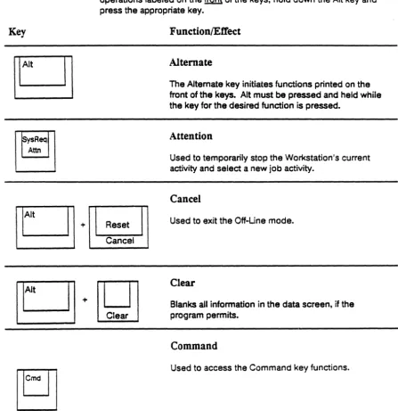
[image:44.620.95.543.253.714.2]When you press a control key, the Workstation performs a specific operation. Pressing a control key does not enter a character on the screen. The control keys and their functions are described in the table below. Auto-repeat keys are marked with an asterisk; these keys automatically repeat when you hold them down.
The Alt key functions similarly to the Shift key. To select
operations labeled on the front of the keys, hold down the Alt key and press the appropriate key.
Function/ElTec:t
Alternate
The Alternate key initiates functions printed on the
front of the keys. Alt must be pressed and held while the key for the desired function is pressed.
Attention
Used to temporarily stop the Workstation's current activity and select a new job activity.
Cancel
[g
lt + ' - - - _ ResetUsed to exit the Off-Une mode. Cancel
IFIlrrll
L:::=::J
+~
Clear
Blanks all information in the data screen, if the program permits.
Command
Control Key Functions
Key
[~J
ntn
EraseL::::::::J
+ L..--1np----,utField Exit
-4-2
Function/EtTect
Delete
Deletes the character at the cursor. All characters in the same field move to the left.
Display Next Record/Enter Data
Displays the next record on the screen (when application is so programmed). Data already entered is sent to the host.
Duplicate Record
Duplicates the information in the previous record into the field where the cursor is pOSitioned. A duplicate
character fills the field to indicate successful
duplication. (Some fields cannot be duplicated; an error message will be displayed.)
Enter the SetUp Mode
Allows operating characteristics to be changed. in On-Une or Off-Une modes. After changing parameters. press the SetUp key again to enter the changes. See the section on SetUp.
Erase Input
Erases information from all input fields and returns cursor to Home position.
Exit Any Data Field
Key
Field +
o
w
rFIl
+n
L===:J
~
FunctionlElTect
Exit Data Field
Fills the rest of a data field with blanks and moves the cursor to the next data field. In right-adjust fields. data is aligned to the right. In assigned numeric fields. a blank fills the last position.
Help
Information about an error condition or an operation of the current application (when application is so programmed) is displayed. To continue entering data. press Reset.
Hex Key
Used to enter a character's hexadecimal code. After Alt and Hex are pressed. the next two numeric characters entered are treated as the hexadecimal value of a displayable character (which may not appear on the keyboard). The character will be displayed at the cursor position.
Home
Moves the cursor to the Home position or to the first input position on the screen.
Insert
Begins insert mode. The next character keyed is inserted at the cursor. All characters in the same field move to the right. "INS" appears in the Status Une.
Control Key Functions
Key
*
-*
Function/EtTect
Mode Key
When used with the E key, the Mode key causes the Select Emulations screen to be displayed. When on-line, the Mode key along with the Print key accesses the Printer Control screen.
Move Cursor Back One Character
Moves the cursor back one character.
Move Cursor Down
Moves the cursor down one line or wraps around to the top of the page when pressed with the cursor atthe bottom of the page.
Move Cursor
Left
Moves the cursor to the left, or wraps around to the previous line when the cursor is at the start of a line. With the Shift key, moves the cursor at 3 times the regular speed.
Move Cursor Right
Moves the cursor to the right, or wraps around to the next line when the cursor is at the end of a line. With the Shift key, moves the cursor at 3 times the regular speed.
Move Cursor to Next Field
Key
Play
I
TestFunction/EiTect
Move Cursor to Next Line
Moves the cursor to the first position of the next line with an input field.
Move Cursor to Previous Field
Moves the cursor to the previous first postion of an input field.
Move Cursor Up
Moves the cursor up one line or to the top of the page when the cursor is at the bottom of the page.
Playback Recorded Keystrokes
Starts Playback mode. See the section on Record/Playback keys.
The information in the data area of the screen is sent to the assigned printer.
Record Keystrokes
Starts and ends record mode. See the section on Record/Playback keys.
Control Key Functions
Key
4-6
B
+0
+0
~
Function/EiTect
Roll Screen Down
Displays the next screen.
Roll Screen Up
Displays the previous screen.
Shift
Accesses the upper case characters.
Shift Lock
Locks the shift key on. Shift Lock is released when the Shift key is pressed.
System Request
Used to notify the host system that the Workstation is selecting a new activity or a new program.
Test
Used to enter diagnostic testing. See the section on DiagnostiCS.
Text Assist
Control
Key
Functions
for the 102 key Keyboard
Key
B
o
[QJ
t
The control keys and their functions are described in the table below. Pressing a control key does not enter a character on the screen. Auto-repeat keys are marked with an asterisk; these keys automatically repeat when you hold them down. The Alt key functions similarly to the Shift key. To select operations labeled on the
front of the keys, hold down Alt and press the appropriate key.
Reset Dvenl
Function/EtTect
Alternate
The Alternate key initiates functions printed on the front of the keys. Alt must be pressed and held while the key for the desired function is pressed.
Attention
Used to temporarily stop the Workstation's current activity and select a new job activity.
Cancel
Used to exit the Off-Une mode.
Clear
Blanks all information in the data screen, if the program permits.
Delete
Deletes the character at the cursor. All characters in the same field move to the left.
Duplicate Record
Duplicates the information in the previous record into
En*
Control Key Functions
Key
t
Shiftt
Shift-J
FieldExit
n::n
~
4-8lEn
+0
+ Erase InputFunction/EJTect
Enter Data
Sends the data entered on the screen to the host system.
Enter the SetUp Mode
Allows operating characteristics to be changed, in On-Une or Off-Une modes. After changing parameters, press the SetUp key again to enter the changes. See the section on SetUp.
Erase Input
Erases information from all input fields and retums cursor to Home position.
Exit
Any
Data Field
Moves the cursor to the first position of the next field.
Exit Data Field
Fills the rest of a data field with blanks and moves the cursor to the next data field. In right-adjust fields, data is aligned to the right. In assigned numeric fields, a blank fills the last position.
Help
Information about an error condition or an operation
ot
the current application (when application is so programmed) is displayed. To continue entering data, press Reset. 'Hex Key
Key
8*
o
~+~or
•
-Backspace
FunctionlEtTect
Home
Moves the cursor to the Home position or to the first input position on the screen.
Insert
Begins insert mode. The next character keyed is inserted at the cursor. All characters in the same field move to the right. "INS" appears in the Status Une.
Insert Minus Sign
in
Numeric Field
In assigned numeroc fields, places a minus sign in the last position. If the cursor is not positioned in an assigned numeric field, a letter fills the last position.
Mode
EJJ
When used with the E key, the Mode key causes the Select Emulations screen to be displayed. When Print on-line, the Mode key along with the Print keyaccesses the Printer Control screen.
Move Cursor Back One Character
Control Key Functions
Key
~.
~.
..
Tab
[~J
~.
4-10
FunctionlEtTect
Move Cursor
Left
Moves the cursor to the left. or wraps around to the previous line when the cursor is at the start of a line. With the Shift key. moves the cursor at 3 times the regular speed.
Move Cursor Right
Moves the cursor to the right. or wraps around to the next line when the cursor is
at
the end of a line. With the Shift key. moves the cursor at 3 times the regular speed.Move Cursor
to
NeJt Field
Moves the cursor to the first position of the next input field to the right.
Move Cursor to Next Line
Moves the cursor to the first position of the next line with an input field.
Move Cursor to Previous Field
Moves the cursor to the previous first postion of an input field.
Move Cursor Up
Key
Print SysReq Reset Dvenl8*
o
1Rl*
o
+ F17F15
PiaF16
F14
RecrdFunction/EtTect
Playback Recorded Keys
Starts the Playback mode. See the section on Record/Playback keys.
The information in the data area of the screen is sent to the assigned printer.
Record Keystrokes
Starts and ends record mode. See the section on Record/Playback keys.
Reset
When an error message is displayed, the Reset key unlocks the keyboard. Also ends an insert.
Roll Screen Down
Displays the next screen.
Roll Screen Up
Displays the previous screen.
Shift
Accesses the upper case characters.
Control Key Functions
Key
n::n
~
n::n
~
rFIlD
~+CJ
4-12
Function/EfTect
System Request
Used to notify the host system that the Workstation is selecting a new activity or a new program.
Test
Used to enter diagnostic testing. See the section on Diagnostics.
Text Assist
Control Key Functions
for the 83-key Keyboard
Key
B
o
Error Reset
When you press a control key or key sequence, the Workstation performs a specific operation. Pressing a control key does not enter a character on the screen. The control keys and their functions are described in the tabl&below. Auto-repeat keys are marked with an asterisk; these keys automatically repeat when you hold them down. The Error Reset key functions Similarly to the Shift key. To select operations labeled on the front of the keys, hold down the Error Reset key and press the appropriate key.
FunctionlEffect
Attention
Used to temporarily stop the Workstation's current activity and select a new job activity.
Cancel
Used to exit the Off-Une mode.
Command
Used to access the Command key functions.
Delete
rrtn
m!ill
*
t=:J+CJ
Deletes the character at the cursor. All characters in the same field move to the left.Duplicate Record
Control Key Functions
Key
Error Reset Enter/ Rec/Adv[g.
Field + Field Exit ' -4-14 F,rase nput Home '-Function/EtTect
End Insert
Ends the insert mode. The next character keyed will
replace the character at the cursor.
Enter Data
Sends the data entered on the screen to the host system.
Erase Input
Erases information from all input fields and returns cursor to Home position.
Exit
Any
Data Field
Moves the cursor to the first position of the next field.
Exit Data Field
Fills the rest of a data field with blanks and moves the cursor to the next data field. In right-adjust fields, data is aligned to the right. In assigned numeric fields, a blank fills the last position.
HeJp
Key
Erase
liiput
Home
rTBl
D
~.
*
Function/EfTect
Home
Returns the cursor to the Home position.
Insert
Begins insert mode. The next character keyed is inserted at the cursor. All characters in the same field move to the right. "INS" appears in the Status Une.
Insert Minus Sign in Numeric Field
In assigned numeric fields, places a minus sign in the last position. If the cursor is not positioned in an assigned numeric field, a letter fills the last position.
Move Cursor Back One Character
Moves the cursor back one character.
Move Cursor Down
Moves the cursor down one line or wraps around to the top of the page when pressed with the cursor at the bottom of the page.
Move Cursor Left
Control Key Functions
Key
4-16
*
[§J
~.
rn=:llrr:ll
~·eJ
Function/ElTect
Move Cursor Right
Moves the cursor to the right. or wraps around to the next line when the cursor is at the end of a line. When used with the Shift key, moves the cursor at 3 times the normal speed.
Move Cursor to Ne:tt Field
Moves the cursor to the first position of the next input field to the right
Move Cursor to Next Line
Moves the cursor to the first position of the next line with an input field.
Move Cursor to Previous Field
Moves the cursor to the previous first postion of an input field.
Move Cursor Up
Moves the cursor up one line or to the top of the page when the cursor is at the bottom of the page.
Playback
Key
Error Reset
Error Reset
Error Reset
Error Reset
+~
+~
+~
Function/EfTect
The information in the data area of the screen is sent to the assigned printer.
Printer Control
Accesses the printer control screen of the printer.
Record Keystrokes
Starts and ends record mode. See the section on Record/Playback keys.
Error Reset
When an error message is displayed, the Error Reset key unlocks the keyboard.
Roll Screen Down
Displays the next screen.
Roll Screen Up
Displays the previous screen.
SetUp
Control Key Functions
Key
Ellrr;Tl
~+t::J
4-18
Function/EtTect
Shift
Lock
Locks the shift key on. Shift Lock is released when the Shift key is pressed.
System Request
Used to notify the host system that the Workstation is selecting a new activity or a new program.
Test
Record/Playback Keys
The Record/Playback keys give you the capability of storing a series of keystrokes and later inputting them to the display with one keystroke. When you play back keystrokes, the Workstation treats them as though you were entering them through the keyboard. The 24 Command keys are used as the "addresses" of the recorded keystrokes. Any Playback key can store up to 1024 keys; the total for all 24 keys cannot exceed 1024. The Workstation will keep track of available space for you.
Record/Playb~ck
Keys
Record
1
To begin recording keystrokes, use the proper key sequence for your keyboard: Keyboard type Key sequence 122-key Record key 102-key Alt and Rec keys ~83-key Error Reset and R keys A blinking "R" appears in the Status Une to indicate that the Workstation is in theRecord mode. At the bottom of the screen, the message "SELECT KEY" appears.
-
...
2
Select one of the 24 Command keys to "address" the recorded keystrokes. Keyboard type Key sequence122-key 24 Command keys in the cluster at the top of the keyboard.
102-key Function keys for Command keys 1 - 12 and the Shift key and the function keys for Command keys
13 - 24.
83-key Numbered keys along top row for Command keys 1 -13 and Shift and numbered keys for Command keys 13 - 24.
2
Select one of the 24 Command keys to "address" the recorded keystrokes. On the 122 key keyboard, use one of the 24 Command keys in the cluster at the top of the keyboard. With the 102 key keyboard, use the function keys for Command keys 1 through 12 and the Shift key and the function keys for Command keys 13 through 24.The "R" on the Status Line will stop blinking. The number of keystrokes recorded for that Playback key and the available recording space in memory
(DODO to 1024) are displayed on the message line.
StS
3
Enter the keystrokes you want to save. Note: Any keystrokes except Play. SetUp. Record, or Mode can be used. Record/Playback keys must be used independently and cannot be nested together. Note: Only one Enter keystroke can be used in a recorded sequence.The characters are displayed in the data area of the screen. The available buffer space displayed for the key and for the Record/Playback functions decreases as you type until the total remaining counter reaches zero. If the available space in memory is filled. an error tone sounds.
4
To save the keystrokes. press the Record key. With the 102 key keyboard press the Alt and Rec keys. The Workstation saves the keystrokes inRecord/Playback Keys
Previously Assigned Keys
If the Command key you choose as the playback address has been previously assigned a keystroke sequence, the Workstation beeps and displays the error message:
• To leave the contents intact and end the Record process, press the Record key again. With the 102 key keyboard press the Alt and Rec keys.
• To write over the contents, type the keystrokes you wish to store. The new keystrokes will overwrite all of the previously recorded keystrokes.
• To erase the contents of the key entirely, press the Alt and Cancel keys.
Typing Errors
Use the backspace or cursor keys to correct the mistakes. These keystrokes will be recorded.
Erasing a Single Command Key
If you wish to erase a single command key sequence, enter the Record mode, select the key to be erased, and press the Alt and Cancel keys. The
Workstation will automatically exit the Record mode.
Erasing All Playback Keys
If you wish to clear all information stored in all 24 playback keys while in the Record mode, press the Alt and Erase Input keys. The available space in memory will return to 1024, and all information previously recorded will be erased.
Playback
1
To play back a previously recorded keystroke sequence, move the cursor to the location on the screen where you want the stored information entered.2
Press the Play key(s).Keyboard type Key sequence 122-key Play key
102-key Alt and Play keys 83-key Error Reset and P keys A blinking "PH appears in the Status Une to indicate that the Workstation is in the
Playback mode. At the bottom of the screen, the message "SELECT KEY" appears. (If you decide not to play back a recorded sequence, press the Play key again.)
--3
Press one of the 24 Command keys that you have previously assigned as an address for a keystroke sequence.Record/Playback Keys
Invalid Playback Keys
If you press any key other than a Command key or the Reset key, or if you press a Command key that has no recorded keystrokes, an error tone will sound and either the "INVALID KEY" message orthe "UNRECORDED KEY" message will be displayed.
"
...
_ '-o To play back a recorded sequence, press a valid Command key. o To cancel the Playback mode, press the Play or Reset key.
Note: If the "INPUT INHIBITED" message occurs during a playback sequence, the data will not be input. The playback will automatically continue after the
"INPUT INHIBITED" message clears.
Fault Isolation Procedures
Your Workstation has six replaceable modules: the keyboard, the CRT display, the logic module, the "smart T" connector, the cartridge, and the power cord. This problem solving guide will help you to isolate the problem.
To begin problem-solving, first make sure that the Workstation is unlocked by turning the security key clockwise. Then determine when the problem appeared, and start at either number 1, 2, or 3 below. If you're not sure when the problem appeared, start at number 1.
If you have any problems following these procedures, call DDCC Marketing Support for assistance.
When Did the Problem Occur?
1.
PROBLEM OCCURRED BEFORE SIGN-ONIs there an error code or an error message displayed on the screen?
Yes
Go to Pathway B.No
Go to Pathway A.2.
PROBLEM OCCURRED AT SIGN-ON OR AFTER SIGN-ON Go to Pathway B.3.
INTERMITTENT PROBLEMSIs there a problem with the display?
Yes
Go to Pathway B.No
Go to Pathway C.Fault Isolation Procedures
Pathway A
In this section, you will start diagnosing the problem by looking at the red and green lights on the logic module. The base is vented on the right side at the rear, and the logic module lights are visible through these vents. Position the Workstation so that you are looking at the back of the base. Then look through the vent on your right.
IS ONLY THE LOGIC MODULE GREEN LIGHT ON?
6-2
No
Turn off the power. Wait 15 seconds. Turn the power on. Wait 15 seconds. Is only the green light on?Yes
Go to PathwayB.
No
Compare the lights to the table below.Logic Module Lights
Red light on steady. Red blinking and a four second beep sounds. Red blinking and no beep sounds.
Red and green lights on.
All lights off.
Yes
Go to Pathway B.Resolution
Replace the logic module. Cartridge not installed or not seated properly. Install the cartridge properly.
Replace the cartridge. Replace the logic module.
Power Test
To run the power test, check the CRT lights, which can be seen through the vents at the top rear of the CRT display. There should be one green light and three red lights visible through the vents. ARE ALL FOUR CRT LIGHTS OFF?
Yes
Check the circuit breaker. The circuit breaker is a round button next to the power cord on the back of the CRT. Check the CRT lights again. Are all four lights on now?Yes
Your Workstation should be OK. If the circuit breaker trips repeatedly, replace the CRT display.No
•
Check your AC power supply. If your outlet is faulty, repair it. If your outlet is OK, check the Workstation power cord; try exchanging cords with a station that is working. If the cord is faulty, replace it.• If your AC power and your power cord appear OK, reptace the CRT display.
No
Are all three red lights on?Yes
Check the cable from the CRT to the logic module. • If the cable is loose, turn off the power, and reconnectthe cable. Your Workstation should be OK.
• If the cable appears OK, replace the logic module. If this does not correct the problem, replace the CRT display.
Fault Isolation Procedures
PathwayB
Turn off the Workstation and check the keyboard cable. If it is loose, resecure it. Then turn on the power. If the problem continues, find the appropriate description below and follow that procedure.
An "L" or error code appears on the Status Line.
• Replace the logic module.
An "KL" error code appears on the Status Line.
• Turn the power off. Unplug the keyboard from the logic module. Turn the power on. If the error code does not appear, replace the keyboard. If the error code appears, replace the logic module.
A "K" error code appears on the Status Line when the power is turned on.
• Turn the power off and on again. If the error code appears again, exchange keyboards with a station that is working. If the error code still appears, replace the logic module; if the error does not reappear, replace the keyboard.
• If the problem continues, replace the logic module.
A "NV" error code appears on the Status Line during normal operations.
• Press the Reset key. Re-enter the setup parameters. Power the Workstation off and on again. If the error code still appears, replace the logic module.
An error code or error message is displayed on the Status Line.
6-4
• Consult the list of error codes in Appendix A for errors
One or several keys display the wrong characters or no characters.
• First, check that the keyboard 10 is set correctly. Unless your System Operator has told you otherwise, keyboard 10 should be two dashes (see the section on Initial Start-up).
• Perform the keyboard test. (See the Diagnostics section.) • If the keyboard 10 is set cQrrectly and the problem continues,
replace the keyboard.
• If the problem still continues, replace the logic module. Is the sign-on display on or blinking, and the system available indicator off or the system available indicator blinking?
Yes
•
Check that all cables are attached to the CRT display correctly and securely.• Check that the "smart T" twinax connector is securely fastened to the CRT display. (See the Installation section.)
• Check the channel address setting, the address of the printer, and that the proper emulation is selected.
• Do you share a cable with other terminals?
Yes
If other terminals are having the same problem, notify your System Operator. If your terminal is the only device on the cable that has the problem, replace the logic module. If the problem continues, replace the smart T connector.No
Replace the logic module. If the problem continues, replace the smart T connector.Fault Isolation Procedures
There is a display problem. For example, the screen is out of focus, all or part of the screen is shrunk, or the screen is warped, tilted, or too dark with the
brightness set at maximum.
The display is blank.
• Check the channel address setting.
• Check that no other station on your cable is using the same channel address setting.
• Turn the power off, remove the cartridge, and check that you are using the right cartridge, that the label is facing up when
inserted, and that the cartridge is seated properly.
• If the channel address is OK, replace the CRT display. If the problem continues, replace the logic module.
• Run the Power test. The display contrast or brightness is too low.
• Check the contrast and brightness settings. If they are set too low, readjust them (see SetUp).
• If the contrast and brightness settings do not work, run the Keyboard test (see the Diagnostics section). Did the keyboard pass?
Yes
Replace the logic module.No
Replace the keyboard.• If they need frequent readjustment, replace the CRT display. Displayed characters have pieces missing or have extra dots.
• Replace the logic module.
The cursor or attributes do not work correctly.
• Make sure the cursor and attributes are set up in the desired way.
• Replace the logic module. The security keylock does not work correctly.
• Turn the security key counterclockwise. Does the "LCK" keylock indicator appear?
Yes
Turn the security key clockwise. Does the "LCK" keylock indicator appear?Yes
Make sure the CRT cable connector is firmly seated. If the problem continues, replace the CRT display. If the problem still continues, replace the logic module.No
Your Workstation should be OK If your problem appears again, start your problem-solving over again from the beginning.No
Make sure the CRT cable connector is firmly seated. If the problem continues, replace the CRT display. If the problem stillFault Isolation Procedures
PathwayC
1
Turn off the Workstation.2
Hold down space bar, and turn the power on again. This puts you in Off-Line mode.3
Press the Alt and Test keys to enter the Offline Test screen.4
Select #8 from the test screen.S
Turn the Workstation off. Wait 15 seconds. Then turn the power on again. The Workstation will attempt to run the power-on test; however, because an invalid channel address (7) was entered, it will continue cycling through the tests. Let it run until an error is detected.6
While the power-on tests are running, answer the following question. IS THERE AN ERROR MESSAGE OR ERROR CODE DISPLAYED?6-8
Yes
Go to Pathway B.No
The power on screen should flash every 10-15 seconds. If the power on screen does not flash after 15 seconds, check the lights on the logic module and compare them to the table below.Logic Module Lights
Red light on steady. Red blinking and a four second beep sounds. Red blinking and no beep sounds.
Red and green lights on. All lights off.
Resolution
Replace the logic module. Cartridge not installed or not properly seated. Install the cartridge properly.
Replace the cartridge Replace the logic module.
PathwayD
In this section, you can isolate problems that occur when
attempting to print from your Workstation. When you encounter any printing problems the first thing your should check is that your printer is properly set up to receive print commands from the Workstation. Make sure the printer is plugged in to an AC outlet, that your printer is powered on and connected to the Workstation, and that the printer is online and selected. If you cannot print your job after you've checked these basics, go to the appropriate section below and follow that procedure.
System Addressable Printer Fault Isolation Procedures
Identify one of the following conditions and follow that path to solve your printing problem: