Accurate and Cost-Effective Mini CNC Plotter
Sara Raad Qasim
Computer Engineering, Alfarabi University
Baghdad, Iraq
Haider Mohammad
Computer Engineering, Alfarabi University
Baghdad, Iraq
Mustafa Falah
Computer Engineering, Alfarabi University
Baghdad, Iraq
ABSTRACT
A Computer Numerical Control (CNC) plotter machine is a computerized numerical control machine which can be used to draw anything or design any mechanical parts according to the design program. The utilization of CNC machine is increased rapidly due to the growth of technology in industries. The fabrication of a low cost CNC plotter becomes a persistent need. In this paper, a low cost, medium size and accurate mini CNC plotter is designed using simple and low cost components: a microcontroller (Arduino), stepper and servo motors and their control software. Software has been used to produce a G code for the operation of the system; G code is an effective language in which people tell the machine tools ‘How to make something’. G code allows the machine to sketch the plots by converting the instructions of that plot into a readable format by the motor driver telling these motors where to move (the machine in this paper can draw maximum dimensions 270m*210m) & how fast to move.
Keywords
CNC, MCU, MIT, Arduino UNO, IDE
1.
INTRODUCTION
Computer Numerical Control (or CNC) [1] is an advanced form of automatic machine that used widely to control the motion of these machine tools. Numerical control machine was first invented around in 19th century to minimize the load of the work [2]. Its advantage ensures higher efficiency, higher flexibility, and low production cost, a little working time and a little loss in production. It mainly follows three steps that are receiving data, interpreting them and react accordingly [3].
To direct the machine function, a special codes and numbers form sequential commands (instructions) that are used to operate the machine automatically and to produce a specific part with specific dimension. These instructions (program) are then converted in to an electrical signal and act as input to the motors which run the machine and do the basic movements[4].
A machine control unit (or MCU) decides the tool depth of draw, drawing speed etc. Motion of tool is based on Right hand coordinate system. Three axis of rotation (x, y & z) for three dimensional motion of tool and for specific role plus an axis of rotation. The x-axis serves as height stands and uses two pieces one for front and one for back. The y-axis acts as motor mount to move z-axis in addition with slide mechanism whereas the z-axis controls the depth by allowing the movement of router in up and down direction so it is very important axis[5][6].
1.1
History of CNC
The idea of numerical control began when the automation of machine tools originally incorporated specific concepts of programmable logic [7]. In the beginning, the first machines
were constructed in the 1940s. But more advanced machines came along in the 1950s. These new NC machines were built based on existing tools that were modified with motors designed to move machine's controls. These first mechanisms were soon improved with both analog and digital computers[8][9].
After World War II, specifically in 1949, John Parsons found methods to improve aircraft by creating stiffened skins for them. This led to important Air Force research projects, which conducted at the Massachusetts Institute of Technology (MIT). After the research phases, an experimental milling machine was designed at MIT. Professor J.F. Reintjes with his team of researchers were involved in this project.
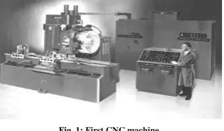
[image:1.595.318.545.397.530.2]In the 1960s and 1970, a very familiar form of a CNC machine started taking shape. Digital technology then entered the fray, and automation in production processes became more efficient than ever [10]. Figure 1 shows the first CNC machine.
Fig. 1: First CNC machine
1.2
The most famous CNC machines
1.2.1 CNC Milling
A CNC milling is a machine process that uses computerized controls and rotating multi-point cutting tools to progressively remove material from the workpiece or cut different materials such as metal, plastic, glass, and wood, and produce a custom-designed part or product (see Figure 2)[11][12].
[image:1.595.326.534.624.749.2]1.2.2 CNC Lathes
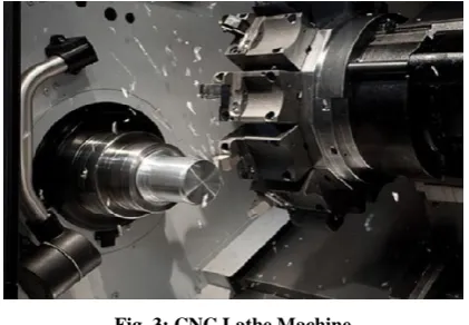
[image:2.595.318.544.74.233.2]CNC lathe is a CNC machine that used to cut workpieces as they are turned. CNC lathe can make exact cuts rapidly by utilizing different apparatuses (see Figure 3). The result is a beautifully finished product so that these machines are very successful in the exactness they offer contrasted with manual lathe. They are used by many industries to include automotive, electronics, aerospace, firearm manufacturing, sporting, and much more [13].
Fig. 3: CNC Lathe Machine
1.2.3 CNC Routers
[image:2.595.62.273.173.319.2]A CNC router is very similar in concept to a CNC milling machine. It is a computer-controlled cutting machine related to the hand-held router used for cutting various hard materials, such as wood, composites, aluminium, steel, plastics, glass, and foams. CNC routers (shown in Figure 4) can perform the tasks of many carpentry shop machines such as the panel saw, the spindle moulder, and the boring machine. They can also cut mortises and tenons. CNC router diminish waste and increment efficiency, creating different things in a considerably shorter measure of time than utilizing different machines [14].
Fig. 4: CNC Router
1.2.4 CNC Plasma Cutters
[image:2.595.327.529.328.547.2]A CNC plasma system is a machine that carries a plasma torch, and can move that torch in a path directed by a computer. The procedure of plasma cutting includes the cutting of a material utilizing a plasma burn. This strategy is most ordinarily used to cut overwhelming materials, for example, steel and different types of metal. CNC plasma cutter is shown in Figure 5 [15].
Fig. 5: CNC Plasma Cutter
1.2.5 CNC Electric Discharge Machines
Electric discharge machining, or EDM for short (see Figure 6), includes making a particular shape inside a specific material by utilizing electrical releases, or starts. The material is expelled from a particular workpiece by a progression of repeating electrical releases between two anodes. These anodes are isolated by a dielectric liquid, which regularly gets an electric voltage [16].
Fig. 6: EDM
2.
MAIN
COMPONENTS
OF
MINI CNC
PLOTTER
The block diagram of mini CNC plotter is shown in Figure 1:
Fig. 1: Simple block diagram of mini CNC plotter
2.1
Input Device
[image:2.595.58.280.468.620.2] [image:2.595.319.550.595.687.2]2.2
Interface
Interface Unit contains many components that help in programming and interfacing the input device into the sketching unit. These components include:
1. Two Stepper Motors
2. Two A4988 Stepper drivers
3. One MG 90S Micro Servo motor
4. CNC v3 shield
5. Arduino Uno R3
2.2.1
Stepper Motor
[image:3.595.331.518.159.283.2]A stepper motor is a brushless DC electric motor that divides a full rotation into a number of equal steps (see Figure 2). Stepper Motors represent the heart of CNC plotter. Two stepper motors are used for x and y axis for precise control over drawing pen (sketching unit) for object sketching. They have important role such that they control the size and type of speed, accuracy, CNC router precision etc. [17].
Fig. 2: Stepper Motor
[image:3.595.72.266.295.397.2]The axis of CNC machine (x, y & z) is based on the right hand coordinate system (rotation is counter clockwise about the axis of rotation as shown in Figure 3) [18].
Fig. 3: The CNC axes
2.2.2
Stepper Driver
[image:3.595.335.520.388.496.2]Stepper motor drivers (as shown in Figure 4) are specifically designed to drive stepper motors, which are capable of continuous rotation with precise position control, even without a feedback system. They offer adjustable current control and multiple step resolutions, and they feature built-in translators that allow a stepper motor to be controlled with simple step and direction inputs. In this project we use two drivers for the two stepper motors [17].
Fig. 4: Stepper Driver
2.2.3
Servo Motor
Servo motor controls the up and down movement of drawing pen in z axis direction It controlled by sending an electrical pulse of variable width, or Pulse Width Modulation (PWM) and this can be achieved using the microcontroller. It determines the position of the shaft, through the control wire, which represent the z axis [19].
Fig. 5: Servo Motor
2.2.4
CNC Shield
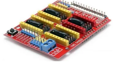
CNC shield V3.0 can be used as drive expansion board for engraving CNC machine. It has 4 slots in the board for stepper motor drive modules that can drive 4 stepper motors. Each stepper motor need two IO port only, that is to say, 6 IO ports can quite well to manage three stepper motors as shown in Figure 6. It is very convenient to use with the microcontroller (Arduino) such that it is placed above the Arduino [20].
Fig. 6: CNC Shield
2.2.5
Arduino
[image:3.595.78.255.441.540.2]Arduino Microcontroller (Here Arduino Uno is used as shown in Figure 7) controls the position of the stepper motors with the help of program instructions. This microcontroller is an open source platform based on both hardware and software that very easy to use. It has 14 digital and 6 analog input/output pins that can incorporate into various expansion boards [21][22].
Fig. 7: Arduino Uno
Arduino programs are written in C++ programming language with a compiler that produces binary machine code.
2.3
Sketching Unit
[image:3.595.340.517.601.705.2] [image:3.595.85.256.659.735.2]pen or pencil and will be controlled by the three motors.
3.
PROJECT CONNECTIONS
[image:4.595.318.542.74.194.2]To build the base of CNC, several wooden pieces are cut which have made holes and blind holes and a wooden table (40cm * 40cm table is used in this paper) which form the base and support of the machine. The screwed steel rods (which were taken from an old wardrobe sliding door) operate as a worm drive. The blind holes serve as a stop for the steel bars that act as guides for the x-axis. In the middle, the screwed steel bar was put, that when turning, generates displacement in the x-axis as shown in the figures below:
Fig. 8: Project Connections
[image:4.595.319.544.78.316.2]The electronic connections include the connection of the stepper motor driver above the CNC shield then placing the CNC shield above the Arduino as shown in Figure 9. For simplicity two drivers were used for the two stepper motors (marked by 1 and 2 in Figure 9).
Fig. 9: Stepper Drivers with CNC Shield Connection
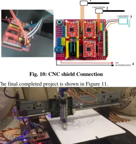
Other complementary components must be connected to the CNC shield as shown in Figure 10.
Fig. 10: CNC shield Connection
The final completed project is shown in Figure 11.
Fig. 11: Final Project Connection
4.
PROJECT SOFTWARE
At the beginning all the required software must be setup in the input unit (the computer). First Inkscape software was used which converts images or text into a code called G code. G code is a special code that consists of the dimensions of the image (x, y, z) and such that it gives the way that the motors move from one point to another and at specified speed. Then the simulator or G Code sender was used. It communicates with the CNC machine through the com port of the computer which connected it with the microcontroller (Arduino) (com3 was the port in this design). Through the G Code sender the image is opened as a link (by the Inkscape) and sent it to the CNC machine. Finally the IDE software must be used to program the Arduino. This program acts only as interface through which the code is uploaded to the Arduino and knew the com port.
4.1
Inkscape
[image:4.595.58.288.200.526.2]Inkscape (see Figure 12) is a free and open-source graphics editor. It is professional quality vector graphics software which runs on Windows, Mac OS X and GNU/Linux. It is used for creating G code for a wide variety of graphics such as illustrations, icons, logos, diagrams, maps and web graphics [23].
[image:4.595.68.270.596.711.2] [image:4.595.321.535.626.749.2]4.2
Simulator - G Code Sender
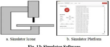
[image:5.595.57.280.167.264.2]G Code Sender is a GRBL compatible, cross platform CNC control software. Its features a highly optimized and asynchronous (event-driven) UI and USB-to-Serial communication and can be also used on computers with small amount of RAM and CPU. It is used to transfer G Code files to CNC machines running G Code interpreters (3D printers, milling machines ...etc) (see Figure 13) [24].
Fig. 13: Simulator Software
4.3
Integrated Development Environment
(IDE)
[image:5.595.55.279.393.543.2]Arduino IDE is a piece of free software that enables users to program in the language that based on C/C++ and can even be extended through C++ libraries. The IDE (see Figure 14) enables users to write a computer program, which is a set of step-by-step instructions that you then upload to the Arduino. Arduino will then carry out those instructions and interact with whatever you have connected to it. In the Arduino world, programs are known as “sketches” [25].
Fig. 14: IDE Software
5.
PROJECT PROGRAMMING SCHEME
[image:5.595.57.280.597.746.2]Figure 15 shows the project scheme in simple manner. It also provides a complete understanding of the whole project software and their roles.
Fig. 15: Simple Project Scheme
6.
CONCLUSION
In this project, Small drawing machine or mini CNC was built. It is a digital electromechanical machine with digital control through a piece of wood and low cost components. Two main axes (x & y) and a vertical axis (z) were used to draw image or figure with a specific dimension and speed. This project design was success prototype design since it can draw any figure or image easily and in a short time as compared to human drawing time.
7.
ACKNOWLEDGEMENTS
The authors gratefully acknowledge Alfarabi University of the pacific for their CNC project. The following individuals have assisted the authors in gathering information and photos for his research on CNC. With thanks, they are Omer Amer and Abdulla Jamal.
8.
REFERENCES
[1] Nanfara F., Uccello T., Murphy D. 2001. The CNC workshop. Prentice Hall, 2nd Edition.
[2] Karthick M., Sundarraj M. and Raja T. 2017. Design and Control of ATC for Shorter Time Interval in CNC Machines. IJMET, 8(3), 77–88.
[3] Kumar A., Ganesh M. and Bindu G.H. 2016.. Application of CNC Milling in Manufacturing Turbine Blades. IJCIET, 8(5), 801–808.
[4] Kumar M. A., Krishnaraj J. and Reddy B. G. S. 2017. Mini CNC 2D Sketcher for Accurate Building Drawing. IJCIET. 8(6), 543–549.
[5] Madekar K.J., Nanaware K.R., Phadtare P.R. and Mane V.S. 2016. Automatic mini CNC machine for PCB drawing and drilling. IRJET, 3(2), 1106–1110.
[6] Xu, X., Li, Y., Sun, J. & Wang, S. 2012. Research and development of open CNC system based on PC and motion controller. Procedia Engineering, 1845–1850.
[7] Pahole I., Rataj L., Ficko M., Klancnik S., Brezovnik S., Brezocnik M. and Balic J. 2009 .Construction and evaluation of low-cost table CNC milling machine. Scientific Bulletin, Series C, Mehcanics, Tribology, Machine Manufacturing Technology, Vol.XXIII, 143-148.
[8] Yesaswi Ch.S., Subrahmanyam, T., Karthik, G.S., Sudheer, N .S. and Farooq, S. B. 2017.Modeling and Analysis of A CNC Milling Machine Bed with Nano Material (Graphene). IJMET, 8(5), 372–379.
[9] Saifee A.M. and Mehta S.U. 2016. Design and Implementation of FPGA Based G Code Compatible CNC Lathe Controller. IJECET, 7(1), 2016, pp. 87-100.
[10] Computer Numerical Control, http://www.cnc.com/the-history-of-computer-numerical-control-cnc/.
[11] Armsrego E.J.A., Brown R.H., 1969. The Machining Of Metals. Englewood Cliffs,N.J , Prentice Hall, 2nd Edition.
[12] Thomasforindustryhttps://www.thomasnet.com/articles/c ustom-manufacturing-fabricating/understanding-cnc-milling/.
[13] WorthyHardwareCo.,https://www.worthyhardware.com/ cnc-lathe-machine-function/.
[15] ESABcompany,https://www.esabna.com/us/en/education /blog/what-is-a-cnc-plasma-cutter.cfm.
[16] E. Jameson, " Electrical Discharge Machining", Society of Manufacturing Engineers, 2001.
[17] Wikimedia Foundation, Inc., USA https://en.wikipedia.org/wiki/Stepper_motor (view at 25 May, 2019).
[18] Theyer G.E. 1991. Computer Numerical Control Of Machine Tools. Butterworth-Heinemann.
[19] Techopedia,ITEducationSite,https://www.techopedia.co m/definition/13274/servo-motor
.
[20] PinetreeElectronicsLtd,Canadahttp://osoyoo.com/2017/0 4/07/arduino-uno-cnc-shield-v3-0-a4988/ (view at 22 May, 2019).
[21] Smith A.G. 2011. Introduction to Arduino: A piece of cake!, Alan G. Smith.
[22] LCSC Electronics, 2018. China's Leading Electronic Components Distributor. Report on Arduino UNO "Arduino UNO Datasheet", China https"//components101.com /microcontroller/Arduino-uno (view at 20 May, 2019).
[23] Softonic International, S.A. Barcelona,Spain https://inkscape.ar.softonic.com/ (view at 3 April, 2019).
[24] Filecroco website for free software download, 2018. https://www.filecroco.com/download-universal-gcode-sender/ (view at 5 April, 2019).