Effects of Transmit Diversity on a Discrete Wavelet
Transform and Wavelet Packet Transform-based
Multicarrier Systems
Rameez Asif
Faculty of Engineering and Informatics, University of BradfordBradford, West Yorkshire, BD7 1DP, U.K
M. S. Binmelha
Faculty of Engineering and Informatics, University of BradfordBradford, West Yorkshire, BD7 1DP, U.K
Asmaa Hameed
Department of Laser and Optoelectronic Engineering,College of Engineering, Al-Nahrain University Baghdad,
Iraq
Raed Abd-Alhameed
Faculty of Engineering and Informatics, University of Bradford
Bradford, West Yorkshire, BD7 1DP, U.K
J. M. Noras
Faculty of Engineering and Informatics, University of Bradford
Bradford, West Yorkshire, BD7 1DP, U.K
ABSTRACT
This paper proposes a MIMO-WPT-based multicarrier system with feedback from the receiver to the transmitter carrying the channel state information (CSI), whereby a steering matrix can be defined to enhance robust performance against multipath fading effects at the receiver. This relies on the time-scale localization of wavelet bases, and is demonstrated in terms of bit error rate performance. In contrast to sinusoidal carriers WP have very narrow side lobes, with most energy contained in the main lobe; this makes the proposed system less susceptible to inter-carrier interference. The main contribution of this work is the evaluation of system parameters using different wavelet families, order of filters and number of elements to balance overall performance and cost of the system, and to provide a reliable system with a high data-rate.
Keywords
MIMO, Wavelet, Transmit Diversity, Beam-forming, Multicarrier System
1.
INTRODUCTION
The fundamental issue in communication theory is to transmit information through an unreliable multipath channel with minimum distortion. Most researchers divide their approaches into two, treating source coding or channel coding, although these are strongly interrelated in real world problems. However, by using Shannon’s source channel theorem these problems can be handled as two independent entities and can be addressed without much loss in the overall system performance, although for particular channel classes only [1]. Source coding techniques are implemented to reduce redundancy in data, minimizing the amount of data to be transmitted. Usually a discrete digital representation is preferred such as a discrete binary bit stream. Much research has focused on using source coding to enhance multi-rate signal processing [2 - 4].
Channel coding then adds additional information to the minimized source-coded data to combat the effects of the channel. Optimal performance can be achieved if this can be based on the specific channel characteristics. Channel coding,
modulation schemes and use of different waveforms are still less explored areas in the field digital communications and can play a vital role in the advancement of wireless systems. Currently Orthogonal Frequency Division Multiplexing (OFDM) systems using the fast Fourier transform lead the market because of their ability to increase the symbol period of the transmitted symbol and so counter the degrading effects of multipath environments. However, the orthogonality of the OFDM subcarrier is highly sensitive to frequency errors and signal phase offsets. Also, the truncation of windowing in OFDM causes production of subcarrier side lobes with a frequency spectrum which is not band-limited [5]. The first side lobe generated by the FFT processing is only 13 dB less than the main lobe, generating inter-carrier interference when the sub-carriers lose their orthogonality. In mitigation, a guard interval is added, equivalent to the channel delay response, but this results in less efficient transmission.
Some blind methods have been proposed for both CDMA and OFDM-based systems [6-7]. In [6] the authors have implicitly made use of time diversity, and proposed a filter design to convert the stationary transmitted signal to a cyclo-stationary form so that a second order method can be derived.
The radio frequency channels for wireless communications usually contain multiple paths because of reflections and diffraction due to obstacles and the resultant multiple signals are then superimposed at the receiver. If the received signals combine destructively the signal can suffer attenuation. A typical figure would be around 35 dB. Depending upon the total system bandwidth, fading can be flat or frequency selective. When dealing with mobile systems it will be time-varying [8].
Diversity techniques are used to mitigate the negative effects of fading, classified into different techniques as spectral diversity, spatial diversity, or time diversity.
Wavelet-based systems use wavelet pulses which have discrete time and frequency localization as compared to the discrete time rectangular pulses with ideal unlimited response in the frequency domain. The use of wavelets for signaling was also proposed as a bandwidth efficient modulation in [11-12]. In [13] the authors proposed using wavelets for user signature waveforms to improve the cross correlation of the pseudo-random codes. In [14] another wavelet-based CDMA
[image:2.595.58.537.152.331.2]system was proposed, and in [15] the authors applied a wavelet packet-based CDMA system to design an optimal joint detector. In [16] authors found significant performance improvement of quadrature amplitude modulation using wavelet packets, and in [17] an optimized wavelet packet multiplexing algorithm was proposed after the study of the timing error effects. The idea of
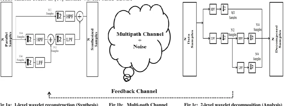
Fig 1a: 1-level wavelet reconstruction (Synthesis) Fig 1b: Multi-path Channel Fig 1c: 2-level wavelet decomposition (Analysis)
forward error correction (FEC) and wavelet packet multiplexing was introduced in [18] for MC-CDMA channel equalization methods in section 5, simulation results in 6, followed by the conclusions.
None of the work cited above utilized the time localization properties of wavelets. Firstly, the research proposes a new wavelet-based multi-rate modulation scheme and its system model for multi user communication over a Rayleigh fading channel which proved to be a great tool in successfully mitigating the fading effects in multipath environments. The proposed system can be implemented for both forward and reverse links. The proposed treatment does not consider interference types such as shadowing, hostile jamming, military applications, or co-channel interference.
Secondly, MIMO and beam-forming are employed using an antenna array at the transmitter with two elements to provide temporal diversity to the multi-user system. A complete parametric study has been carried out to find the best communication system architecture. The research considers the behavior of different wavelet transforms, families, and filters, and suggest one that has the best reconstruction properties for use in a multicarrier (MC) system. The proposed system consists of three aspects: 1) using wavelets to reduce ICI and multipath fading and to reduce bandwidth usage, 2) using MIMO to ensure high data-rates and 3) beam-forming for good link reliability. Most of the processing burden is kept at the Base-Station (BS) with less cost and power constraints.
The paper is divided as follows. Section II provides a background in wavelet analysis, sub-band coding and perfect reconstruction of filter banks, Section III will describe the system model, Section IV deals with the error probability and transmit beam-forming, followed by the simulation and results in Section V, with conclusions in Section VI.
2.
WAVELET ANALYSIS
Wavelets transform decomposes a signal into its constituent components corresponding to different scales, covering different frequency ranges. There are three different transform
methods namely: a) the dyadic wavelet transform [19] in which logarithmic band division is achieved using a two band wavelet transform, b) using wavelet packets by employing the full dyadic tree decomposition [19], and c) n-band wavelet analysis [8], which divides the spectrum into equal-sized bands. Wavelets are quickly decaying oscillations deriving from a basis function, the mother wavelet, with translated and scaled replicas known as daughter wavelets [20]. Signal analysis can use any of an infinite number of basis functions to isolate the information required, in contrast to other signal analysis methods.
The continuous wavelet transform can be mathematically defined as [20]:
(1) Here stands for the scaling factor, for the shifting parameter and “ is the mother wavelet. In its
continuous form the transform requires extensive analytical calculations due to data redundancy and no practicable inverse exists for this transform other than in theory, so is restricted to discrete valued data. In order to accomplish this we choose
and where and are integers with fixed values of and Then we have:
(2)
(3)
(4)
(5)
Any signal with a finite amount of energy can be successfully reconstructed by using (4). The coefficient of the wavelet transform is linked to a fastidious scale for fastidious number of times, orthonormal transform. We can define the DWT of any random signal as its product with the scaling and wavelet function [20] as:
(6)
where is the scaling function and is called the wavelet function. These functions are discretized at
and at translation . The DWT is implemented in a MCM system using a Perfect Reconstruction Quadrature Mirror Filter Bank (PR-QMF) with a half-band high-pass filter and a half-band low-pass filter . These filters values can be calculated as:
(7)
The filters satisfy the conditions:
(8)
The resulting DWT can be written to express the approximation and detailed coefficients in a mathematical form as;
(9)
Due to shifting and translation of the wavelet signal, each of the composite symbols suffer a delay by a factor ‘ ’ according to the z-transform relation ( , where ) for which adjacent matched filters are required to perfectly reconstruct the signal. This condition can be written as:
(10a)
(10b)
2.1
Sub-Band Coding and Perfect
Reconstruction
Sub-band coding is very useful in signal, audio and video coding applications. The input signal s(m) is decomposed into N different frequency sub-bands, using the analysis filter bank as shown in Figure (1c). These are down-sampled to get
and then quantized. The quantized outputs
are then up-sampled to (with ( and
summed to get an output signal using the synthesis filter bank as shown in Figure (1a).
Now for such a filter bank to be employed in a MCM it must be nearly perfect reconstruction filter bank in practical life, when no quantization is performed (in theory (perfect reconstruction)) can be defined as;
[image:3.595.347.513.105.234.2]The conditions that the filters need to follow have been shown in (10a) and (10b).
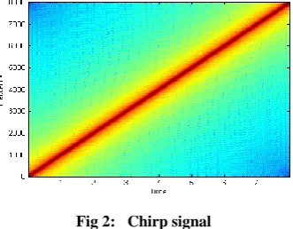
Fig 2: Chirp signal
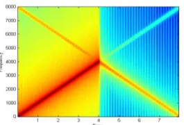
In Figure 2 - 3 it has been shown that how the signal gets replicated when it is directly up-sampled or down-sampled by 2 without the filters being present. In Figure 4 down-sampled and up-sampled signal using low pass synthesis filter is shown and lastly in Figure 5-6 a signal that has been down-sampled and up-sampled using the low-pass (analysis and synthesis filter) and high-pass (analysis and synthesis filter) is shown and Figure 7 shows the reconstructed signal of two channel filter bank.
Fig 3: Replicated chirp signal due to up-sampling and down-sampling without filter bank employment
3.
SYSTEM DESIGN
The system that is considered is for a wireless cellular network with many users connected to the same base station even though it can be used for several other applications. The communication between the base station and the mobile user which is the forward link and mobile user to base station or reverse link is essential and requires non-interfering channels [21]. A general system model is shown in Figure (1 and 9). At the transmitter, the incoming bit stream with a bit rate of (K/LM) is represented as (12);
(12)
This stream is then serial to parallel converted to yield (13)
(13)
where K represents the bit duration of this super stream, and
[image:3.595.337.520.349.453.2]Fig 4: Output of a low-pass filter in a synthesis filter part
To implement wavelet transform in a MCM system the inverse transform needs to be implemented at the transmitter as shown in Figure 1. Using the PRQMF the parallel symbols are first up-converted by a factor of two and then passed through the high pass filter (HPF) and low pass filter (LPF). This convolution between the symbols and the filters can be mathematically described as;
[image:4.595.345.541.244.379.2]
(13) These resultant approximate coefficients from the LPF and detailed coefficients from the HPF are then summed to constitute a wavelet symbol. The process of IDWT is also referred to as a Synthesis Process. This synthesized signal then propagates through the Rayleigh multipath fading channel in the presence of noise. For greater understanding of the process of convolution with the filters and channel please refer to authors [12].
Fig 5: Up-sampled and down-sampled output of filter bank with LPF.
3.1
WMCM signal in Rayleigh Multipath
Channel and AWGN
T The signal when propagated through the Rayleigh fading channel suffers phase and amplitude changes, time delay and the mathematical Equation in (12) can very well summarize this effect.
(12)
where , represents the amplitude and the time delay is represented by and , phase shift for any rth multipath at time instance t can be described as ( . Multipath summation limits are from r = 1 to R, where R stands for the total number of multipaths with the Dirac delta The resultant received signal at the receiver can be given as [22].
(13)
The effects of the multipath propagation caused by the media fluctuations and the transmitter and receiver motion are captured at time instance of n for the mth sample for the unit time sample n-m in . Noise and any other type of interferences present in the system are captured by the . If the kernels in (13) are zero mean and Gaussian the resultant channel will be the Rayleigh fading channel [22].
For frequency selective channels the magnitude of the time variant frequency response varies for every n as a function of and is independent of for flat fading channels and can be mathematically written as (14):
[image:4.595.103.236.440.530.2]
(14)
Fig 6: Up-sampled and down-sampled output of filter bank with HPF.
3.2
Implementation WMCM in Receiver
When the signal is received at the receiver it is passed through the conjugate LPF and HPF . The signal is decomposed into its approximate and detailed coefficients and then down-sampled by a factor of 2. This process is repeated until the desired N data streams are successfully recovered. A parallel to serial conversion is applied next which is followed by a suitable de-mapping scheme.
Fig 7: Resultant signal from 2-channel filter bank
3.3
Implementation of WPMCM
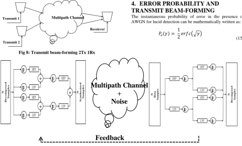
[image:4.595.341.514.505.615.2]Fig 8: Transmit beam-forming 2Tx 1Rx
4.
ERROR PROBABILITY AND
TRANSMIT BEAM-FORMING
The instantaneous probability of error in the presence of AWGN for lucid detection can be mathematically written as:
(15)
Fig 9a: 2 Level WPT- Synthesis Process Fig 9b: Rayleigh Multipath Channel + AWGN Fig 9c: 2 level WPT- Analysis Process
However, now this error probability will change if the beam forming is applied and can be given as;
(16) where the probability density function (PDF) of the output signal is represented by , however this value will depend on the PDF of the input signal.
To implement transmit beam-forming system two or more antennas are required at the transmitter. This technique is then applied to every subcarrier of the WMCM system at the baseband level. A steering matrix is computed which is used to steer the transmitted signal in the direction required. The transmitter weights that are applied in the steering matrix are derived using the channel state information (CSI) which is provided by the receiver in the closed loop systems.
Unless the phases of the signals from two different antennas align at the receiver no diversity gain can be achieved because of each transmitted signal will traverse through a different Rayleigh multipath channel so the overall system performance will be equal to a SISO system.
Mathematically the implementation of this technique can be realized as;
If ‘s’ is the transmitted symbol and ‘h’ is the channel impulse response then;
(17)
where n is AWGN. When two different transmitters are employed then (17) can be modified to add another independent channel and can be written as;
(18)
If the channels have phases and respectively. As there is a closed loop between the receiver and the transmitter and CSI is known Equation (18) can be further modified using steering matrix to;
(19) The received signal ‘y’ is then passed through the DWT and Equalized.
5.
SIMULATION RESULTS AND
DISCUSSION
This section presents the performance of the proposed system and the parametric studies that were done. The performance of different wavelet families, impact of filter order, diversity order and the performance of DWT and WPT have been considered. For simplicity, BPSK modulation was used for the proposed final system and the parameters used for each simulation have been described in the corresponding tables. All the results presented in this paper are through computer simulations using MATLAB and are solely based on numerical integration.
5.1
Performance Comparison of Wavelet
Families
Figure 10 and Figure 11 show the performance of two initial systems employing two different transform methods, i.e. DWT and WPT. From the results, it can be seen that when DWT is employed orthogonal, biorthogonal and reverse biorthogonal wavelets perform alike. If the order of filter is increased, the performance degrades in the case of biorthogonal and reverse biorthogonal wavelets because these wavelets don’t have good reconstruction properties, while orthogonal wavelets have been applauded for their reconstruction properties, so even the signal is decomposed more rigorously and many more coefficients need to be
Multipath Channel
Transmit 2 Transmit 1
Receiever
Multipath Channel
+
Noise
recovered to construct the original transmitted signal, orthogonal wavelets were shown to do that with ease.
[image:6.595.54.284.277.402.2]Fig 10: DWT-based MCM system with different wavelet family filters
Table I Modulation Parameter for Comparison of WP and DW using Orthogonal, Biorthogonal and reverse biorthogonal
wavelets
DWT WPT
Modulation 16-QAM 16-QAM
Symbol length 2^6 * 10^4 2^6 * 10^4
Channel Rayleigh Multipath
Fading
Rayleigh Multipath Fading
Noise AWGN AWGN
Decomposition Levels
Log2(n), n = 64; Log2(n), n = 64;
Antennas 1 Transmit,
1 Receive
1 Transmit, 1 Receive
In Figure 11 however even the lower order biorthogonal and reverse biorthogonal wavelets cannot compare to the orthogonal Daubechies wavelets; reason being the decomposition at every node of the wavelet packet which will require a wavelet that has good reconstruction properties to recover the signal correctly. Daubechies wavelets however performed alike regardless of the transform employed. Any orthogonal wavelets (e.g. Daubechies, Symlet, Coiflet) will show the same performance in AWGN and Rayleigh channels [23]. The answer to the question of the effect of filter order in orthogonal wavelets is addressed later in the discussion. The reason for selecting a higher order modulation technique for this simulation was to study the performance of these wavelets for high data-rate systems and complex mapping.
Fig 11: WPT-based MCM system with different wavelet family filters
5.2
BER performance of orthogonal
wavelet families
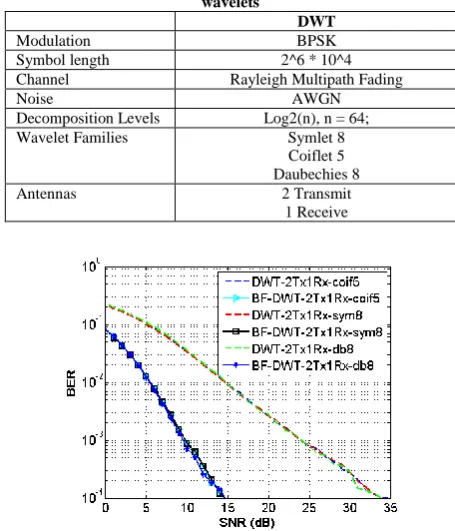
Figure 12 shows a comparison between three different orthogonal wavelet families. It has been suggested in [23] that all orthogonal wavelets perform alike which is true in the case of BER performance both with and without beam-forming but the system processing time considerably varies between them. In this study, it was noticed that the processing time of the Daubechies wavelet filters of order 8 had the fastest processing followed by the Symlet filters of order 8 and the Coiflet filters of order 5 had the slowest processing. The reasoning behind this is how the coefficients of these wavelets behave which is out of the context of this paper but the reader is referred to [24] for a general idea of the difference. This difference is important in the case of digital image processing but for effective communication system purposes Daubechies 8 is better suited.
TABLE II Modulation Parameter for Comparison of WP and DW using Orthogonal, Biorthogonal and reverse biorthogonal
wavelets
DWT
Modulation BPSK
Symbol length 2^6 * 10^4
Channel Rayleigh Multipath Fading
Noise AWGN
Decomposition Levels Log2(n), n = 64;
Wavelet Families Symlet 8
Coiflet 5 Daubechies 8
Antennas 2 Transmit
[image:6.595.313.541.283.549.2]1 Receive
Fig 12: Comparison of different orthogonal wavelet families using DWT
5.3
BER performance of DWT with
beam-forming and effect of the order of diversity
This part of the study studies the behavior of different wavelet families, performance comparison between a low order Daubechies filters and high order Daubechies filters, and the effect of order of diversity on the total system performance, to understand other tradeoffs that are required in the systems parameters to achieve a specific diversity gain.
TABLE III Modulation Parameter for Comparison of WP and DW using Orthogonal, Biorthogonal and reverse biorthogonal
wavelets
DWT
Modulation BPSK
Symbol length 2^6 * 10^4
Channel Rayleigh Multipath Fading
Noise AWGN
[image:6.595.73.260.573.730.2]Levels
Daubechies Filter Order
Daubechies 2 Daubechies 8 Daubechies 16
Antennas 2 Transmit, 1 Receive
3 Transmit, 1 Receive
Figure 13 shows that the implementation of Transmit beam-forming considerably improves the system performance due to the prior knowledge of the channel at the transmitter with the help of the feedback loop from the equalizer, through which decision can be made on the phase of the channel and the phases of both transmitted data streams can be constructively combined at the receiver using a steering matrix. The increase in the order of filter marginally improves the system performance due to higher filter coefficients but that also increases the system latency quite a bit. Between the three different filter orders that were used the performance of Daubechies family filter with 8 coefficients can be regarded the best overall when the tradeoff is made based on performance and latency.
[image:7.595.53.281.70.130.2]The system does not show any performance gain by just increasing the wavelet filter order if the beam-forming is not applied. Each data stream encounters an independent channel which makes the equalization at the receiver a challenge and will require more effective techniques which will increase the total receiver cost and power requirements.
Fig 13 Effects of beam-forming and wavelet filter order with 2 transmit elements using DWT
[image:7.595.337.522.75.195.2]In Figure 14 effects on the system performance have been studied by increasing the number of transmitting elements by 1, i.e. from 2 transmit antennas to three antennas which will increase the system implementation cost at the Base Station, power is not a constraint at the Base Station, so it is just the tradeoff between the cost of hardware implementation and maintenance and the performance. It is evident from the results produces that the system gain increases about 5 dB at BER of 10-4 but the overall system gain has decreased to the quarter between the addition of one extra transmit element and two extra transmit elements.
Fig 14: Effects of beam-forming and wavelet filter order with 3 transmit elements using DWT
5.4
BER performance of WPT with
beam-forming and effect of the order of diversity
[image:7.595.71.264.366.491.2]Figure 15 shows the system performance of WPT with beam-forming and the effect of the order of wavelet filters used. In WPT more super channels are created within parallel sub channels as can be seen in Figure 9 which at the end of the filtering process are combined to obtain a wavelet packet. This type of decomposition results in detailed decomposition of signal which results in more number of coefficients. This type of system requires more processing time and can suffer badly from the effects of ISI that is created when the convolution between the channel and the wavelet packet occurs as explained in [12].
Fig 15: Effects of beam-forming and wavelet filter order with 3 transmit elements using WPT
[image:7.595.358.499.379.489.2]This interference is then distributed in different wavelet domain to make the degradation effect minimal. But if the channel response is known and the steering matrix is applied then as can be seen the constructive interference of two signals at the receiver can provide high gain as compared to the three independent streams travelling through a multipath channel.
TABLE IV Modulation Parameter for Comparison of WP and DW using Orthogonal, Biorthogonal and reverse biorthogonal
wavelets
WPT
Modulation BPSK
Symbol length 2^6 * 10^4
Channel Rayleigh Multipath Fading
Noise AWGN
Decomposition Levels Log2(n), n = 64;
Daubechies Filter Order Daubechies 2
Daubechies 8 Daubechies 16
Antennas 3 Transmit, 1 Receive
[image:7.595.316.542.627.733.2]equalize the channel effects and retrieve the original transmitted data. But on the other hand, same system outperforms the DWT-based system when beam-forming is applied for the reasons.
5.5
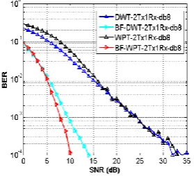
Proposed System compared with DWT
[image:8.595.55.276.175.312.2]Figure 16 shows the performance of the DWT and WPT using beam-forming with two transmit and one receive antennas. The WPT-based system provides the best BER performance.
TABLE V Modulation Parameter for Comparison of WP and DW using Orthogonal, Biorthogonal and reverse biorthogonal
wavelets
DWT WPT
Modulation BPSK BPSK
Symbol length 2^6 * 10^4 2^6 * 10^4
Channel Rayleigh Multipath
Fading
Rayleigh Multipath Fading
Noise AWGN AWGN
Decomposition Levels
Log2(n), n = 64; Log2(n), n = 64;
Antennas 2 Transmit,
1 Receive
2 Transmit, 1 Receive
Wavelet Family
and Order
Daubechies 8 Daubechies 8
[image:8.595.98.238.400.527.2]The WPT-based system provides a higher gain at the cost of extra processing time when compared to DWT with two transmit antennas, but the performance is the same as a 3 element DWT which also takes additional processing time and includes extra hardware cost to implement the third transmit antenna
Fig 16: Comparison of DWT and WPT
6.
CONCLUSION
From the above study, it can be concluded Wavelet Packet Transform-based MCS using Daubechies 8 filters can give the best BER vs. SNR performance using two elements which can reduce the overall system cost, Increase the coverage and reliability of the system, Power burden is all on the transmitter so the receivers can save power. Processing time is slightly increased when WPM is employed but 3 dB to 4 dB is sufficient gain with one less element at the transmitter for this system to be acceptable. An addition of an extra element with DWT-based system will also increase the processing time and the hardware cost. It is also concluded from the results above that for the communication system orthogonal wavelets of Daubechies family show the best overall performance and orthogonal wavelets perform alike in terms of BER but differ in processing time. From the results it is also evident that even though 2x1 transmitters are employed they perform just like a SISO system because of the independent channels and the sudden changes are due to the small symbol length while when the CSI is known and the signal adds constructively at the receiver the error is minimized.
7.
REFERENCES
[1] R. G. Gallager, Information theory and reliable communication, New York: Wiley, 1968.
[2] T. Berger, Rate Distortion Theory: A mathematical basis for data compression, Englewood Cliffs, NJ: Prentice-Hall, 1971.
[3] H. S. Malvar, Signal processing with lapped transforms, Norwood, MA: Artech, 1992.
[4] M. Vetterli and J. Kovacevic, Wavelets and sub-band coding, Englewood Cliffs, NJ: Prentice-Hall, 1995. [5] S. B. Weinstein and P. M. Ebert, Data transmission by
frequency division multiplexing using the discrete Fourier transform, IEEE transaction on communication technology, Vol. 19, pp. 628 – 634, Oct 1971.
[6] H. Bolcskei, P. Duhamel, and R. Hleiss, “A subspace-based approach to blind channel identification in pulse shaping OFDM/OQAM systems,”IEEE Transaction on Signal Processing, Vol. 49, pp. 1594–1598, Jul. 2001. [7] Y. Sun and L. Tong, “Channel equalization using one-tap
DFE for wireless OFDM systems with ICI and ISI,” in Proc. IEEE SPAWC’99, Annapolis, MD, pp. 146–149 May 1999.
[8] G. W. Wornell, Emerging applications of multi-rate signal processing and wavelets in digital communications, Proceedings of the IEEE, Vol. 84, No. 4, pp. 586 – 603, April 1996.
[9] G. W. Wornell and A. V. Oppenheim, “Wavelet-based representations for a class of self-similar signals with applications to fractal modulation”, IEEE transaction on information theory, Vol. 38, pp. 785 – 800, 1992. [10]G. W. Wornell, Signal Processing with fractals: A
wavelet-based approach, Upper Saddle River, NJ: Prentice-Hall, 1995.
[11]F. Daneshgaran and M. Mondin: ‘Bandwidth efficient Modulation with wavelets’, Electronic Letters, Vol. 30, No.1, pp. 1200–1202, July 1994
[12]R. Asif, R.A. Abd-Alhameed, “Performance Evaluation Of FFT-OFDM and DWT-OFDM for multicarrier communications systems using time domain zero forcing equalization”, International journal of Computer Applications, Foundation of Computer Science, NY, USA, Vol. 51, No. 4, pp- 34-38, August 2012.
[13]K. Hetling, G. Saulnier, and P. Das, “Spreading codes for wireless spread spectrum communications,” Proceedings of IEEE, Vol. 1, pp. 68–72, 1996.
[14]A. Muayyadi and M. A. Abu-Rgheff , “Wavelet-based multicarrier CDMA system and its corresponding multi-user detection”, IEE Communication Proceedings, Vol 150, No. 6, Dec 2003.
[15]R. E. Learned, A. S.Willsky, and D. M. Boroson, “Low complexity optimal joint detection for oversaturated multiple access communications,” IEEE Transactions on Signal Processing, Vol. 45, pp. 113–123, Jan. 1997. [16]A. R. Lindsey, “Wavelet packet modulation for
[17]K. M. Wong, J. Wu, T. N. Davidson, and Q. Jin, “Wavelet packet division multiplexing and wavelet packet design under timing error effects,” IEEE Transactions on Signal Processing, Vol. 45, pp. 2877– 2890, Dec. 1997.
[18]R. Asif, R. A. Abd-alhameed, “Performance Evaluation of DWT-OFDM and FFT-OFDM for Multicarrier Communications Systems using Time Domain Zero Forcing Equalization”, International Journal of Computer Applications, vol. 51, no.4, August 2012, pp. 34-38. ISSN: 0975 – 8887..
[19]M. Vetterli and C. Herley, “Wavelets And Filter Banks: Theory And Design,” IEEE Transactions on Signal Processing, Vol. 40, No. 9, pp. 2207 – 2231, Sept.1992. [20]I. Daubechies, Ten Lectures on Wavelets, 2nd Edition.
Philadelphia, PA, USA. CBMS-NSF-Regional Conference Series on Applied Mathematics, 1992.
[21]K. Abdullah, A. Z. Sadik, and Zahir M. Hussain, “On the DWT and WPT- OFDM versus FFT-OFDM”, 5th IEEE GCC Conference and Exhibition, Kuwait City, 17-19, pp 1 – 5, March 2009,
[22]W. C. Jakes, Ed., Microwave Mobile Communications. New York: Wiley, 1974.
[23]R. Asif, “A Unique Wavelet-based Multicarrier System with and without MIMO over Multipath Channels with AWGN.” International Journal of Computer Applications, Vol 17, No. 9, 2015.