RFID based Electronic Voting System using
Raspberry PI
Dr. D.B.Kadam1, Miss. Pooja R. Patil2, Miss.Tejashree N. Patil3 ,Miss.Nandini R.Khot4
1
Associate Professor, 2, 3, 4 UG Students, Department of Electronics and Telecommunication Engg, P. V. P. Institute of Technology Budhgaon, Sangli
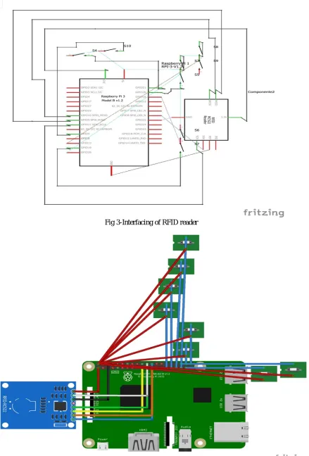
Abstract: The intent of this paper is to design an efficient and effective a secured voting system which utilizes the RDID technology along with the electronic voting machine to further improve the election process and to avoid fake voting. The system we have developed RFID reader, Raspberry pi , Screen. The voter comes to the polling booth to exercise his franchise, he is directed to scan his voter identity card on a RFID reader. The RFID reader senses the voter ID and sends this information to the Raspberry pi. After receiving the voter ID the Raspberry pi checks whether the received voter ID belongs to the particular polling booth or not. If the voter ID belongs to the particular booth the raspberry pi finds if the voter has voted or not. if not, then it the makes the voting machine ready for voting. This process continues for each voter. After implementing the components on the circuit board and programming the SD card, the system worked as expected.
Keywords: Raspberry pi , RFID reader, RFID cards
I. INTRODUCTION
India is an democratic nation where in the people are directly involved in the electing the candidates for the parliament.
Election is a basic process that occupies a prominent place in any democratic company. Many countries are using technology to effectively conduct elections and to smoothen the process.
Here Radio frequency identification based over voter identification is employed. Elections are backbone of democratic system, therefore it is necessary to employee efficient methods of a conducting elections. Recently a massive general election process concluded in India Electronic voting machine are used effectively in these elections.
Though the election commission took extreme care here and their some rigging and malpractices where reported during this election process. It is difficult task for the polling officials also for identifying the authenticity of the voter and to stop rigging.
In that direction we thought of a system which can identify the voter ID and check the voter for authenticity. The Raspberry pi is provided with the data base of all the voters and their RFID cards. After scanning the card from the RFID reader, the Raspberry pi checks the ID of card.
Radio frequency identification reader queries using RF, ID sends its ID using RF. Competes with bar code, magnetic stripes, magnetic Ink Character Recognition (MICR) on bank checks.
A radio frequency identification reader (RFID Reader) is a device used to gather information from an RFID tag, which is used to track individual objects. Radio waves are used to transfer data from the tag to reader.
RFID is a technology similar in theory to barcodes. However, the RFID tag does not have to be scanned directly, nor does it require line of sight to a reader. The RFID tag it must be within the range of an RFID reader, which ranges from 3 to 300 feet, in order to be read. RFID technology allows several items to be quickly scanned and enables fast identification of a particular product, even when it is surrounded by several other items.
RFID tags have not replaced barcodes because of their cost and the need to individually identify every item.
Radio Frequency identification (RFID) uses electromagnetic fields to automatically identify and track tags attached to objects. The tags contain electronically stored information. Passive tags collect energy from a nearby RFID reader's. Active tags have a local power source such as a battery and may operate at hundreds of meters from the RFID reader.
RFID is on method for Automatic Identification and Data Capture (AIDC). RFID is the wireless noncontact use of radio frequency waves to transfer the data.RFID tags are used in many industries.
©IJRASET: All Rights are Reserved
1902
The Raspberry Pi 3 model B is the latest version of the Raspberry Pi computer. The Pi isn't like your typical machine, in its cheapest from it doesn't have a case, and is simply a credit card sized electronic board of the type you might find inside a PC or laptop but much smaller.
The Pi 3 also supports a wireless internet out of the box, with built in Wi-Fi and Bluetooth. Its roughly 50-60 percent better performance in 32 bit mode and 10x faster than other raspberry pi model. The new board is capable of playing 1080p MP4 video at 60 frames per second.
The latest board can also boot directly from a USB attached hard drive or pen drive, as well as supporting booting from a network attached file system. The latest version of Raspberry Pi’s official OS has the chromium browser that chrome is based on. Its performance is reasonable. It is a 64 bit board. The raspberry pi is made by the Raspberry Pi foundation.
Push Button
A push button or simple button switch mechanism for controlling some aspect of a machine or a process. Buttons are typically made out of hard material, usually plastic or metal.
The surface is usually flat or shaped to accommodate the human finger or hand, as to be easily depressed or pushed. Buttons are most often biased switches, though even many un-biased buttons require a spring to return to their un-pushed state. Different people use different terms for the "pushing" of the button, such as depress, mash, hit, and punch.
We have 5 buttons to select the preferred candidate during voting
A. Buzzer
A buzzer or beeper is an audio signaling device, which may be mechanical, electromechanical, or piezoelectric. Typical uses of buzzers and beepers include alarms devices, timers, and confirmation of user input such as a mouse click or keystroke.
The electric buzzer was invented in 1831th by Joseph Henry. They were mainly used in early doorbells. Until they were phased out in early 1930’s in favor of musical chimes, which had a softer tone.
While technological advancements have caused buzzers to be impractical and undesirable, there are still instances in which buzzers and similar circuits may be used.
B. Telegram(Software)
Telegram is a cloud based instant messaging and voice over IP service developed by Telegram Messenger LLP, a privately held company registered in London, United Kingdom, founded by the Russian entrepreneur PavelDurov and his brother Nikolai. Telegram client apps are available for Android, iOStelephone were, Windows phone, Windows NT, macOS and Linux. Users can send messages and exchange photos, videos, stickers, audio and file of any type.
A telegram is a written message transmitted by using an electric device. Telegram were very widely used, because private not usual.
C. Python
Python is an interpreted, high-level, general purpose programming language. Created by Guido van Rossum and first released in 1991, python has a design philosophy that emphasizes code readability, notably using significant whitespace. It provides constructs that enable clear programming on both small and large scale.
Python features a dynamic type system and automatic memory management. It supports multiple programming paradigms, including object-oriented, imperative, functional and procedural. It also has a comprehensive standard library.
Python interpreters are available for many operating systems. The reference implementation of Python, is open source software and has a community-based development model, as do nearly all of pythons other implementations. Python and CPython are managed by the non-profit Python Software Foundation.
©IJRASET: All Rights are Reserved
1904
D. Pin Description
SR NO. PIN GROUP PIN NAME DESCEIPTION
1. Power source +5v,+3.3v,GND and Vin
UART interface (RXD,TXD) [(GPIO15,GPIO14)] +5v-power output +3.3v-power GND - Ground pin UART(Universal asynchronous Receiver
Transmitter) used for interfacing sensors and other
devices.
2. Communication interface SPI
interface(MOSI,MISO,CLK,CE)X2 [SPIO-(GPIO10,GPIO9,GPIO11, GPIO8)] [SPI1-(GPIO20,GPIO19,GPIO21, GPIO07)] TWI Interface(SDA,SCL)*2[(GPIO2, GPIO3)] [(ID-SD,ID-SC)] SPI(Serial peripheral interface)used for communicating with other
boards or peripherals. TWI (Two wire
interface) interface can be used to connect peripherals.
3. Input output pins 26 I/O Although these some pins
have multiple functions they can be considered as a I/O
pins.
4. PWM Hardware PWM available on
GPIO12,GPIO13,GPIO18, GPIO19
These 4 channels can provide PWM(pulse width
modulation) Outputs. *software PWM
available on all pins 5. External interrupts All I/O In the board all I/O pins can
be used as interrupts.
Raspberry Pi 3 Technical Specifications
Microprocessor Broadcom BCM2827 64 bit Quad Core Processor
Processor operating voltages 3.3v
Raw voltage input 5v,2A power source
Maximum current through each I/O pin 16mA
Maximum total current drawn from all I/O pins 54mA
Flash memory(operating system) 16Gbytes SSD memory card
Internal RAM 1Gbytes DDR2
Clock frequency 1.2GHz
GPU Dual core video core iv multimedia Co-Processor
provides open
GLES 2.0,Hardware-accelerated open VG, and 1080p30H.264 High profile decode.
Ethernet 10/100 Ethernet
Wireless connectivity BCM43143(802.11 b/g/n wireless LAN and Bluetooth
4.1)
©IJRASET: All Rights are Reserved
1906
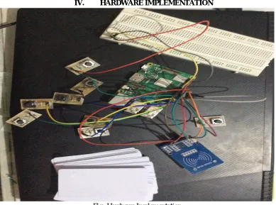
[image:6.612.113.502.79.368.2]IV. HARDWARE IMPLEMENTATION
Fig- Hardware Implementation
V. SOFTWARE DESIGN
Start
Reset Result RFID scan
Is ID valid
If 1
If 2
If 3
If 4
If 5
Total=1+2+3+4+5
Win=Max(1,2,3, 4,5)
Win%=(Win/Total)*100 Total=0
Win=0
1=2=3=4=5=0
Stop
Is ID
Invalid
Variable1++
Variable2++
Variable3++
Variable4++
[image:6.612.113.502.97.651.2]Variable5++
In this flowchart three parts are given. They are RFID scan, Result, Reset. We take 20 cards for voting. Card is scanned on RFID scan if card is valid it goes to further process and voting is done. If one button is pressed many times then this votes are stored in variable blocks. If card is invalid is it goes to start block. Second part is result, in this total no. of voters are counted and winner is declared. Also winner candidate percentage are declared. Third part is reset. If we go to this part all data are reset and all data is
cleared.
A. Result after Implementation
VI. CONCLUSION
©IJRASET: All Rights are Reserved
1908
REFERENCES
[1] Asif Ahmed Anik, RayeesaJameel, Abul Farah Anik, NowrozeAkter “Design of a solar power Electronic Voting Machine”, 2017 International Conference on Networking, Systems and Security (NSysS) Pages: 127 - 131, DOI: 10.1109/NSysS.2017.78 85813
[2] Rodrigo H. Murofushi, Jose J. P. Z. S. Tavares “Towards fourth industrial revolution impact: smart product based on RFIDtechnology” IEEE Instrumentation & Measurement Magazine Year: 2017, Volume: 20, Issue: 2 Pages: 51 - 56, DOI: 10.1109/MIM.2017.79191 35
[3] Anooshmita Das, ManashPratimDutta,Subhasish Banerjee, C. T. Bhunia “Cutting Edge Multi Stratum Secured Electronic Voting Machine Design with Inclusion of Biometrics RFID and GSM Module” 2016 IEEE 6th International Conference on Advanced Computing (IACC) Pages: 667 - 673, DOI: 10.1109/IACC.2016.129
[4] Yuan Ye, YihongRu, Dechen Liu, Jianhua Huang “Study on inbound special goods traceability system on the basis of RFIDtechnology” 2016 International Conference on Logistics, Informatics and Service Sciences (LISS) Pages: 1 - 6, DOI: 10.1109/LISS.2016.7854349