994 | P a g e
DYNAMIC TRAFFIC CONTROL SYSTEM USING
RFID TECHNOLOGY
Prajakta Waghere
1, Priyanka Nalawade
2, Nisha Vanare
3, Prajakta
Kalbho
r
4,
Prof. A.J.Jadhav
51,2,3,4
Department of IT, S. P. Pune University, Pune, India
5Professor,
Department of IT,S. P. Pune University, Pune (India)
ABSTRACT
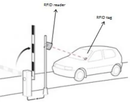
Nowadays, traffic congestion is a major problem in cities of developing countries like India because of the increasing number of vehicles. As result traffic is becoming one of the important problems in big cities and urban areas all over the world. The existing traffic lights follow the static traffic control mechanism. These lights are called static traffic lights. So, we propose a dynamic traffic control system using RFID. In this, each individual vehicle is equipped with the special radio frequency identification (RFID) tag to track the vehicle and we use RFID reader to read the RFID tags attached to the vehicle's windshield. It counts a number of vehicles using IR sensor that passes in a particular direction of the road during a specified duration and set time dynamically for the traffic signal. And it also provides quality of service to emergency vehicles like ambulance, fire brigade or police and also special vehicles like MLA, minister vehicles. When such vehicles with unique RFID tag is read by the RFID reader at the traffic junction then green light will be turned ON for a specific duration.
Keywords - Arduino Microcontroller, IR Sensor, RFID Reader, RFID Tag, Switches.
I.
INTRODUCTION
Dynamic Traffic Control Systems for traffic signals include communication systems, adaptive control systems,
traffic responsiveness, real-time data analysis and collection and maintenance of the system that enable dynamic
traffic control system to operate with greater efficiency. Traffic signal control system coordinates individual
traffic signals to achieve network-wide traffic operations objectives. Traffic light posts are positioned at the
traffic junction. Traffic light set the green passage for a specific period of time which is not a complete
systematic system as it cannot solve the traffic problems fully.
The proposed system will have RFID readers at the traffic junctions and that will read RFID tags attached to the
vehicles coming towards the junction. RFID technology uses digital data within RFID tag, which is made up of
integrated circuits which contain a small antenna for transferring information to RFID readers. The RFID tags
contain an integrated electromagnetic circuit along with antenna for transmitting and receiving RF signals.
Frequency ranges differ from low frequencies of 125 to 134 kHz and 140 to 148.5 kHz, and high frequencies of
850 to 950 MHz and 2.4 to 2.5 GHz. Wavelengths in the 2.4 GHz ranges are limited because they can be
995 | P a g e
Fig. 2.1 Structure of RFID1.1 RFID Technology
Radio-Frequency-Identification (RFID) tag uses electromagnetic signals to identify and track the tags that are
attached to vehicle automatically. The tags contain electronically saved information. Passive tags gain energy
from a nearby RFID reader's interrogating radio waves. Active tags have their own power source such as a
battery and may operate at hundreds of meters from the RFID reader [4].
1.2 Problem Statement
To avoid the traffic congestion problem the proposed system gives the solution using RFID technology. To
control traffic efficiently and avoid the congestion problem in urban areas a combination of RFID tag and RFID
reader are used along with IR sensor. To provide a special service for emergency vehicles such as ambulance,
fire brigades, VIP vehicles, police, etc. As soon as such vehicles are detected the system will dynamically set
green passage to let the vehicles go, also this system provides service for stolen vehicle by reporting to
concerned authority and updating the tag info as stolen for easy detection by RFID this system provides service
for rule violation.
II. ARCHITECTURE
2.1 Architecture of Proposed System
The proposed system consists of an Arduino microcontroller to sense by receiving input from IR sensor and can
affect its surroundings by controlling lights. This system has an RFID tag attached to vehicles that are read when
they pass through traffic junction and thus providing a better service to all vehicle specially the emergency
vehicles like ambulance, fire brigade, police van and also VIP vehicles. It also provides service in case the
vehicle is stolen by reporting to the concerned authority and by updating tag information. This system provides
better enforcement of laws to avoid violation of rules. This system also used to reduce waiting as well as
996 | P a g e
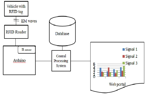
Fig. 2.1 Architecture of Proposed System2.1.1 RFID tag
A Radio-frequency identification tag also called as interrogates that uses electromagnetic signals to
automatically identify and tags equipped to vehicles. The RF energy from the reader is collected by the RFID
tag and used to power up the microchip. This tag is associated with every object and in this case we are
associating the tags with the vehicles so as to provide better services [7].
2.1.2
RFID reader
A radio frequency identification reader is a device used to read information from an RFID tag, which is used to
track individual objects. Radio waves are used to transfer data from the RFID tag to a RFID reader. To control
the traffic the RFID readers will be linked to Arduino Microcontroller. The RFID readers will be allocated time
in round robin fashion and reader reads more number of tags that lane will be set as green passage by the
Arduino Microcontroller. Then microcontroller will continuously transmit the information to central database.
2.1.3
Microcontroller
This microcontroller is used for processing and setting the green passage signal depending upon the count. The
microcontroller is mainly used for manipulating the signals depending on the count of vehicles.
2.1.4
IR Senor
The IR Sensor is a proximity sensor. It is used for detecting the collisions. The module consists of an IR emitter
and receiver. The IR receiver always detects an emitted IR signal. The output of sensor is high whenever the IR
frequency is low. It gives a digital output. IR sensors are used for counting the number of vehicles based on
proximity of vehicle.
2.1.5
Central Processing System
The central database is used for storing the vehicles RFID tag that passes through the traffic junctions. The
stolen vehicle’s RFID tag will be registered at the central database if the match is found then the software send
message to the owner and police station.
2.1.6
Web Portal
The report will be generated and will be displayed on the web portal in the form of graph. This graph will
997 | P a g e
the traffic analysis for particular date and time and according the graph are generated.III. ALGORITHM
3.1 Decision Making Algorithm
While (true)
1. Register all vehicles with RFID/
2. Read the vehicles on different lanes continuously
3. If a high priority vehicle is detected then
1.1. Send an emergency signal to center processing system.
1.2. Find the road corresponding to the reader that detect a high priority vehicle
1.3. Set the corresponding traffic light Green
4. Else
5. For i=1 to 4
5.1. At decision point select the traffic light Queue[i]
5.2. At traffic i Count the number of vehicles & check type of vehicle
5.3. If Emergency vehicle found then
1. Go to step 3
5.4. Else follow steps d to f
5.5. Find the priority depending on count, of the lane at traffic junction i
5.6. Calculate the total sum according to Number of vehicle
5.7. On the basis of count the will be sum calculate for the time of green passage
5.8. If any light doesn’t get it turn within the threshold time then give the turn to that light
6. End Loop
7. En
d [1].
IV.
IMPLEMENTATION
The Arduino microcontroller is used to manipulate the signals. RFID tags are equipped with the vehicles that are
read by the RFID reader at the traffic junction. IR sensors are used to count the no of vehicles that approach
towards the traffic junction. LED lights have been interfaced across each road to represent the traffic signal. The
IR sensor counts the number of vehicles that represent the density of the traffic at the junction. Depending on
the maximum count of vehicle the signal turn to green to allow the dense side to pass through the junction. This
system avoids starvation of vehicles on other side as it also follow round robin algorithm. Likewise all the other
side's functions based on the count of vehicles detected. In a normal condition the traffic light works in a
particular loop. RFID tags are read by the readers that are positioned at traffic junction. If emergency or special
vehicle is detected at the junction Interrupt is given to the microcontroller which takes that as the input and
changes the action by glowing LED green. And after a fixed time the loop continues back to the normal traffic
light system depending on vehicle count. If the vehicle is stolen and information is updated with central
authority then if vehicle is detected at any traffic junction the message will be send to the owner and the
authority.
998 | P a g e
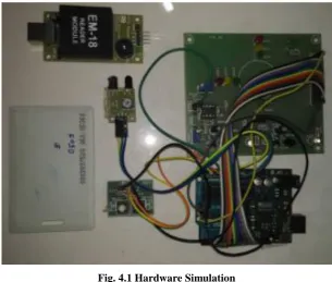
1.Input voltage Vin is 5V through external power source.2.Output pin produces voltage of 5V from the regulator on board.
3.There is one pin grounded.
Fig. 4.1 Hardware Simulation
The hardware consists of an arduino microcontroller through which all the IR sensor are connected internally
along with the RFID readers. Arduino Uno is a microcontroller board based on the ATmega328P datasheet. It
consists of 6 analog inputs pin, 14 digital input and output pins, a USB connection port, a power jack, an ICSP
header and a reset button. They establish a serial communication to communicate with the microcontroller. The
RFID tags used for this system are active tags.
V.CONCLUSION
This paper is basically discusses the traffic analysis in urban cities. The RFID technology and various aspects of
RFID are studied. The proposed system works effectively with higher accuracy in managing the traffic at
junction with different priorities at different time. This system is developed to provide emergency services to
ambulance, VIP vehicles, police vans, fire brigades, etc. and also stolen vehicles. We have tried to find out
reviews of the people and tried to overcome daily traffic problems such as rule breaks, long waiting hours, etc.
using RFID technology.
VI.ACKNOWLEDGEMENT
This project aims at providing a quality of service at the traffic junctions. We are profoundly grateful to Prof.
A.J.Jadhavfor her expert guidance and continuous encouragement throughout to see that this project rights its
target since its commencement to its completion. We are also grateful to Head of Department
Dr.A.N.Banubakode for his support and guidance that have helped us to expand my horizons of thought and
999 | P a g e
REFERENCES
[1] Suresh Sharma, AlokPithora, Gaurav Gupta, MohitGoel, MohitSinha, “Traffic Light Priority Control For
Emergency Vehicle Using RFID”, International Journal of Innovations in Engineering and Technology, vol.2, no.2, pp.363-366, 2013.
[2] RashmiHegde, Rohith R. Sali, Indira M.S., “RFID and GPS based Automatic Lane Clearance System for
Ambulance”, International Journal of Advanced Electrical and Electronics Engineering, vol.2, no.3, pp.102-107, 2013.
[3] Arduino Uno Datasheet: http://arduino.cc/en/Main/ arduinoBoardUno
[4] H. Lehpamer, “RFID Design Principles,” Norwood, MA: Artech House,2008.
[5]AyoubFikri, El Mehdi Zrihni and YassineSalihAlj, “A Smartphone-based System for Traffic Congestion
Control using RFID Tags”, 1st International Conference on Electrical and Information Technologies ICEIT’2015
[6]https://www.elprocus.com/infrared-ir-sensor-circuit-and-working/
[7]A. Chattaraj, S. Chakrabarti, S. Bansal, S.Halder and A. Chandra “An Intelligent Traffic Control System
Using RFID”, IEEE Potentails.