Abstract— The diamond-like coating (DLC) protects the lubricant-starved dry surface of the piston skirts against wear in a low-load and speed initial engine start-up. Despite a relatively large radial clearance a physical contact between the skirts and the cylinder liner causes an elastic deformation of DLC coated surface producing elastic stress and strains of noticeable amplitudes. The elastic stress accumulation may facilitate a subsequent de-lamination of the DLC coating. This study develops the numerical piston dynamics model by incorporating the secondary eccentric displacements of the skirts and their contact with the liner during the 720-degree crank rotation cycle. The contact zone in the boundary-value problem is discretized using the finite difference method and the elastic displacements, stresses and strains are determined by applying the theory of elasticity and solving the Navier's or Lame's equation numerically. The nature and extent of the displacements, stresses and strains produced at the interface of a fairly thin DLC coating with the substrate are analyzed. The results highlight the extent of the depth of the elastic surface displacements, the stresses and strains produced in the coating and the substrate materials. The simulation results show that the dry piston skirts establish a physical contact with the liner in the compression stroke that remains in the expansion and exhaust strokes. The stresses produced at the low-speed are significant, increase beneath the surface and accumulate at the interface between the coating and the substrate. The elastic displacements of a fairly thin DLC coating prevent the stress accumulation on the substrate and protects it from adhesive wear
Index Terms— Initial Engine Start-up, Elasticity, DLC Coating, Dry Contact, Piston Skirt.
I. INTRODUCTION
The piston skirts of an internal combustion (IC) engine establish a physical contact with the liner. It happens in the absence of a liquid lubricant in a few initial cycles of a low-speed engine start up. The dry surfaces of the piston skirts and the cylinder liner contact each other during the cyclic axial piston motion and its eccentric transverse displacements despite a large radial clearance. Under the thermal loading conditions due to combustion a physical contact invites the elastic surface displacements, producing strains and stresses. The stresses and strains accumulate to
This work was sponsored by National University of Sciences and Technology (NUST), Islamabad, Pakistan. Financial support was provided by the Higher Education Commission of Pakistan.
Zahid-Ur-Rehman is Graduate Student at NUST College of Electrical and Mechanical Engineering,Rawalpindi(email: [email protected]) Syed Adnan Qasim is Research Associate at NUST College of Electrical and Mechanical Engineering, Rawalpindi (email: [email protected]) M. Afzaal Malik is Professor at Department of Mechanical and Aerospace Engg, Air University, Islamabad (email: [email protected])
ultimately produce the plastic material flow and wear of the surfaces [1]. Many researchers have worked on modeling the contact mechanics and the forces associated with it to study the elastic and plastic deformation of the contacting bodies [2, 3]. The work was extended to the single-layered coated surfaces to study the action of the concentrated normal and tangential forces analytically [4]. Some workers extended the work on the coated surfaces to 3-D problems employing the theory of elasticity [5]. The bi-layered isotropic coated surfaces were also considered and analytical solutions were obtained for the stress and displacement fields [6]. In some of the cases the normal and frictional distributed loads were applied to study the properties of the stress fields responsible for surface cracks and de-lamination of the coating [7]. In view of the complex nature of the problem the following logical assumptions are made:
1. Thermal effects due to the dry contact are neglected. 2. The transient elastic effects are neglected.
3. The coating is homogeneous and isotropic. 4. The load is uniformly distributed .
5. The surface roughness effects are neglected. II. MATHEMATICAL MODEL
A. Piston's Dynamics
The position, velocity and acceleration along the axis of the cylinder of the piston depend on the crank angle. For constant crankshaft speed, piston speed is [8, 9]:
𝑈 = 𝑌 𝑟𝜔 sin 𝛹 + 𝑟𝜔𝐵 cos 𝛹 𝑙2− 𝐵2 −0.5
(1)
where 𝐵 = 𝐶𝑝+ 𝑟 𝑠𝑖𝑛 𝛹 (2) Table-1 (Input Parameters)
Parameter Value Parameter Value
𝑚𝑝𝑖𝑠 0.295 kg Ɵ = 𝛉1 + 𝛉 2 75 degrees
R 0.0415 m l 0.133 m
L 0.0338 m 𝜐1 ,𝜐2 0.3
𝑚𝑝𝑖𝑛 0.09 kg E1, E2 200 GPa
During its axial translation the piston displaces eccentrically in the transverse direction. The second-order secondary piston displacements along the direction perpendicular to the axis of the liner are defined by the relationships, which are incorporated in the mathematical model. To calculate the eccentricities of the top and the bottom surfaces of the skirts, the forces and the moments are used in the form of the force and moment balance equations [9]:
Modeling Dry DLC Coated Piston Skirts Elastic
Behavior at Low-Speed Initial Engine Start Up
𝑎11 𝑎12 𝑎21 𝑎22
𝑒 𝑡 𝑒 𝑏 =
𝐹 + 𝐹𝑠+ 𝐹𝑓𝑡𝑎𝑛 ∅
𝑀 + 𝑀𝑠+ 𝑀𝑓
(3)
𝑎11 = 𝑚𝑝𝑖𝑠 1 −𝑎𝐿 + 𝑚𝑝𝑖𝑠 1 −𝑏𝐿 (4)
𝑎12= 𝑚𝑝𝑖𝑠𝑎𝐿+ 𝑚𝑝𝑖𝑠𝑏𝐿 (5)
𝑎21 =𝐼𝑝𝑖𝑠𝐿 + 𝑚𝑝𝑖𝑠 𝑎 − 𝑏 1 −𝑏𝐿 (6)
𝑎22 = 𝑚𝑝𝑖𝑠 𝑎 − 𝑏 𝑏𝐿− 𝐼𝑝𝑖𝑠 𝐿 (7)
𝐹𝑠= 𝑡𝑎𝑛Ø (𝐹𝐺+ 𝐹 + 𝐹𝐼𝑃 ) (8) 𝐼𝐶 𝑀𝑠= 𝐹𝐺𝐶𝑝+ 𝐹 𝐼𝐶𝐶𝑔 (9)
B. Contact Geometry Profile The skirts get displaced eccentrically during the primary piston motion. The absence of a liquid lubricant invites a physical contact between the skirts and the liner during the 4-stroke cycle. Considering the radial clearance C, the equation representing the contact profile curve as a function of 720-degree cycle is [9, 11]: = 𝐶 + 𝑒𝑡 𝑡 cos 𝑥 + 𝑒𝑏 𝑡 − 𝑒𝑡 𝑡 𝑦𝐿cos 𝑥
(10)
where
𝜃 ≈
𝑥 𝑅 C. Calculation of Elastic Displacements The desired equilibrium equations in terms of displacements is the Navier’s or Lame’s equation. The scalar form of the system of equations in 2-D is [7, 10] :𝜇𝛻
2𝑤 + 𝜆 + 𝜇
𝜕 𝜕𝑧 𝜕𝑢 𝜕𝑥+
𝜕𝑤 𝜕𝑧= 0
(11)𝜇𝛻
2𝑢 + 𝜆 + 𝜇
𝜕 𝜕𝑥 𝜕𝑢 𝜕𝑥+
𝜕𝑤 𝜕𝑧= 0
(12)The above system of equations can be represented in the vector form as [7, 10]:
𝜇𝛻
2𝒖 + 𝜆 + 𝜇 𝛻 𝛻. 𝒖 = 0
(13)where the Laplacian is given by [10]:
𝛻
2=
𝜕2 𝜕𝑥2+
𝜕2 𝜕𝑧2 (14)D. Boundary Conditions Boundary condition at the top for the uniformly distributed line load is:
𝜎
𝑧= 𝑞; 𝑤 = 0
Boundary condition at the sides and bottom is:𝑤 = 0; 𝑢 = 0
The continuity conditions at the interface are:𝜎
′ 𝑥= 𝜎
𝑥which is the continuity of vertical stress at the interface
𝜎
′ 𝑥𝑧= 𝜎
𝑥𝑧which is the continuity of shear stress at the interface. E. Strain-Displacement Relations The relations enable us to calculate the strains produced due to the elastic surface displacements. The principal strains are calculated as [6, 10]:
𝑒
𝑧=
𝜕𝑤𝜕𝑧;
(15)𝑒
𝑥=
𝜕𝑢𝜕𝑥 (16)The shear strain is calculated as [10]:
𝑒
𝑥𝑧=
12 𝜕𝑤𝜕𝑥+
𝜕𝑢𝜕𝑧(17)
F. Stress-Strain Relations Using Hook's Law, the principal and shear stress components are determined as [6, 12]:
𝜎
𝑥= 𝜆 𝑒
𝑥+ 𝑒
𝑧+ 2𝜇𝑒
𝑥 (18)𝜎
𝑧= 𝜆 𝑒
𝑥+ 𝑒
𝑧+ 2𝜇𝑒
𝑧 (19)𝜎
𝑥𝑧= 2𝜇𝑒
𝑥𝑧 (20)where µ and 𝜆 are lame’s constants are [6, 10]:
𝜇 =
2 1+𝑣 𝐸 (21)𝜆 =
1+𝑣 1−2𝜈 𝐸𝜈 (22)where E = Young’s modulus 𝜈 = Poisson’s ratio
G. Discretization
To solve the Navier's equation numerically a finite difference mesh is generated and an explicit numerical scheme is used to determine the displacements at each node of a 21x300 nodes mesh.
The eccentricities et(t) and eb(t) are calculated by solving equation (3). It constitutes an initial value problem for the two non-linear second order or the four first order differential equations [11]. The values of et,, eb, ėtand ėb are assumed at the time step considered initially. Such values are considered as the initial values for the new time step. On the basis of these values the contact geometry between the skirts and the liner is calculated by solving equation (6). When the values of the eccentric displacement rates ėt, ėb are satisfied and achieved, the piston position at the end of the current time step is obtained as [8, 9]:
) ( ) ( )
(i t i t i
t t t e t te t
e
) ( )
( )
( i b i b i
b t t e t te t
e
We compute and satisfy the secondary acceleration terms ёt,
ёb. These are satisfied from the solution of velocities ėt, ėb at the previous and present time steps. The simulation of second order differential equations show the elastic surface displacements in the contact zone at the respective time steps or crank angles [12]. The Navier's equation is solved to calculate the distribution of the elastic surface displacements, strains and stresses. The Successive-Over-Relaxation (SOR) iterative numerical scheme is used to solve the equations simultaneously. The simulation results correspond to the 720 degree crank rotation and show the deformation, strain and stress profiles[12].
III. NUMERICAL RESULTS AND DISCUSSION
diamond-like carbon (DLC) solid lubricant coating over the surface of the skirts encompasses the incorporation of the secondary dynamics of the piston during the 4-stroke engine cycle. It is essential to ascertain the nature and duration of a physical contact between the skirts and the cylinder liner during the 720-degree crank rotation cycle. The elastic surface displacements occur when a physical contact gets established with the liner during the cyclic piston motion. The piston dynamics model is developed at a very low initial engine start up speed of 500 rpm and solved numerically to generate the simulation results for the analysis. The 720-degree crank rotation cycle is divided into four piston strokes of an equal duration as is the case in reality. The induction stroke is shown from 0-180 degrees, the compression stroke between 181-360 degrees, where as the expansion and exhaust strokes are represented by 361-540 and 541-720 degrees, respectively. The simulation results show the profiles of the secondary piston eccentricities, secondary velocities, the elastic surface displacements on the sides and at the interface of the DLC coating and the substrate. The results would show the stresses and the strains produced due to a physical contact between the skirts and the liner during the 720 degree crank rotation cycle.
A. Piston Eccentricities and Secondary Velocities
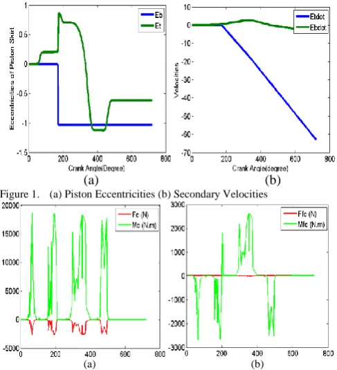
An internal combustion engine considered in our case is assumed to have a piston-to-bore radial clearance of 100 microns at the time of a low-speed initial start up. A relatively large radial clearance and the cyclic nature of the primary piston motion change the nature and duration of the dry physical contact between the skirts and the liner during the 4-stroke cycle. In view of this the secondary eccentric displacements of the piston skirts are shown in the sub-figure 1(a). The secondary displacements of the top and the bottom surface of the skirts or the eccentricities are plotted in the non-dimensional form. The top and the bottom profiles are designated as Etand the Eb for the top and the bottom sides of
the piston skirts, respectively. In the sub-figure 1(a) the three horizontal lines at +1, 0 and -1 show the non-thrust side of the liner wall, its center and the thrust side of the cylinder wall, respectively. The piston commences its journey at zero degree crank angle in the induction stroke and completes its stroke at 180 degree crank rotation angle in the 720-degree cycle. The eccentricity profiles show that the top surface comes close to the non-thrust side of the liner wall at the end of the induction stroke but does not establish a physical contact with it. However, the bottom surface contacts the thrust side of the liner wall at 180 degree. At the end of the induction stroke the piston changes its direction of travel but the bottom surface remains in physical contact with the liner in the compression, expansion and exhaust strokes. The top surface gets displaced all the way from close to the non-thrust side to the thrust side of the liner wall after experiencing the combustion thrust. Combustion occurs at 372-degree crank angle in the beginning of the expansion stroke. It displaces the top surface, which establishes a physical contact with the liner in the first half of the expansion stroke as the piston accelerates towards the mid-point of the expansion stroke. In the second half of the expansion stroke the piston decelerates towards the bottom dead center (BDC) as the combustion thrust subsides. It results in the physical disengagement of the top surface from the thrust side of the liner. In the exhaust stroke the bottom surface remains in contact with the liner but the top surface avoids a physical contact as shown in the
sub-figure 1(a). The sub-figure 1(b) shows the dimensionless velocity profiles of the top and the bottom surface of the skirts represented as Etdot and Ebdot, respectively. It represents
the rate of energy transfer that takes place between the skirts and the liner surfaces. In the figure the velocity profiles are plotted in the positive and the negative quadrants. The respective profiles in the positive quadrants show the energy transfer from the skirts to the liner and vice versa in case of the profiles shown in the negative quadrant. The velocity profile curves explain the magnitude of energy transfer that allows a physical contact between the skirts and the cylinder liner. For the establishment of a physical contact the bottom surface require a relatively low amount of energy transfer during the induction stroke as compared to the case of the top surface. The small amount of energy transfer from the liner to the bottom surface is insufficient to allow a disengagement of the skirts during the remaining three piston strokes. It is not the case when the energy transfer between the top surface and the liner is considered. The rate at which energy is transferred from the liner to the top surface is appreciably high resulting in a surface disengagement in the second half of the expansion stroke.
B. Contact and Friction Forces
In view of the secondary piston displacements and the contact profiles the normal friction force and contact friction force acting over the surface are studied. The magnitudes of these forces and the moments generated are estimated and plotted against the 4-stroke cycle, as shown in figure 2. The normal force profile in the sub-figure 2(a) shows an instantaneous rise and fall at the mid-point and end of an induction stroke. During the process the there is an insignificant amount of energy transfer between the skirts and the liner. It implies that entropy increases as the skirts do not get displaced significantly in the lateral direction. It is also evident from the contact friction force profile shown in the sub-figure 2(b). An instantaneous increase and reduction of the contact friction force is shown in the negative quadrant. It indicates a low efficiency process implying irreversibility and energy loss. The significant and noticeable changes in the magnitudes of the forces are seen in the second half of the compression stroke and first half of the expansion stroke. The effects are seen in the eccentric displacements of the skirts and the energy transfer in the form of the secondary velocity profiles. There is a negative friction force profile in the second half of the expansion stroke. It affects the lateral eccentricities of the top surface, which gets disengaged from the liner during the process.
C. Elastic Surface Displacements
Figure 3 shows the three profiles of the axial surface displacements. On the application of the contact loads there are significant elastic surface displacements generated at the interface of the DLC coating layer and the substrate skirts material. In view of the surface displacements the possibility of plastic flow and wear may be estimated by showing the extent and place of the maximum deformation at the interface. The sub-figure 3(a) shows the axial deformation at the interface and along the width of the skirts. The parabolic profile of the axial displacement curve shows the maximum deformation at the mid-point and the negligible value at close to the distant side of the skirts. The applied load affects the
displacements is shown in the sub-figures 3(b) and (c). The elastic displacement is maximum at the surface of the DLC coating and decreases linearly as the depth increases. The displacements at the depth of 70 microns thick coating are linear in nature but the slope differs slightly from that of the substrate, as shown in the sub-figure 3(c). The transverse elastic deformation at the interface of the coating and the substrate is shown in the sub-figure 4(a). The profile shows that the surface deformation increases initially but then decreases sharply till the mid-point of the skirts surface. The point of inflexion at the mid-point allows an increase in the elastic displacement till the two-third of the width of the skirts surface. However, the deformation decreases to a negligible value after approaching the second point of inflexion. Initially the transverse elastic surface deforms linearly followed by the second-order changes experienced by the displacement curve resulting in an energy transfer between the coated surface and the liner. Figures 5 and 6 show the contour and 3-D plots of the axial and transverse deformations, respectively. The contour plots show the
relatively high deformation intensities close to the surface. D. Axial and Transverse Strains
The axial and transverse elastic surface displacements produce the corresponding strains. The profile curves of the strains generated at the interface and in the depth of the coating and substrate material are plotted and shown in the sub-figures 7(a) and 8(a), respectively. The axial strain curve at the interface does not vary significantly along the width of the skirts. However, the transverse strain curve shows the cyclic behavior along the surface width. When studying the strains produced in the depth of the coated surface, the results show that the maximum axial strain is produced at the surface of the coating. In contrast, the maximum transverse strain is produced at a depth of 5cm, which implies that the maximum overall strain is produced over the surface of the coating at 5cm away from the origin. The contour plots and 3-D fields of axial and transverse strains are plotted and shown in figures 9 and 10, respectively.
E. Principal and Shear Stresses
On the application of an external load the principal stresses are produced in the axial and transverse directions apart from the shear stress over the coated surface of the skirts. The principal stresses are studied at the interface and the depth of the skirts surface and the results are shown in figures 11, 12, 14 and 15, respectively. In the axial direction the stress has the nearly uniform magnitude at the interface and along the width of the skirts. When considering the depth the stress increases in the coating, attains the maximum value and then decreases linearly in the substrate. Similarly, in the transverse direction the maximum stress is produced within the coating. The contour and 3-D plots show the stress intensities. There is maximum shearing of the DLC coating layer as compared to the case of the substrate, as shown in figure 13.
[image:4.595.304.550.42.630.2]
(a) (b)
Figure 1. (a) Piston Eccentricities (b) Secondary Velocities
(a) (b)
Figure 2. (a) Normal Contact Force and Moment Vs 720-degree cycle (b) Contact Friction Force and Moment Vs 720-degree cycle
(a) (b) (c)
Figure 3. Axial Deformation (a) Along Skirts Width at Coating Interface with Substrate (b) In the Depth (c) In the Critical Depth
(a) (b) (c)
Figure 4. Transverse Deformation (a) Along Skirts Width at Coating Interface with Substrate (b) In the Depth (c) In the Critical Depth
[image:4.595.305.549.50.318.2] [image:4.595.303.548.299.742.2]Figure 6. Transverse Deformation shown by Contour and 3-D Plots
(a) (b) (c) Figure 7. Axial Strain (a) Along Skirts Width at Interface with Substrate (b) In Depth (c) In Critical Depth
Figure 8. Transverse Strain (a) Along Skirts Width at Coating Interface with Substrate (b) In Skirts Depth
Figure 9 . Contour and 3-D Plots of Axial Strain
Figure 10. Contour and 3-D Plots of Transverse Strain
(a) (b) (c)
Figure 11. Principle Stress in Axial Direction (a) Along Skirts width at Coating Interface and Substrate. (b) In depth (c) Critical depth
(a) (b)
Figure 12. Principle Stress in Transverse Direction (a) Along Skirts width at Coating Interface and Substrate. (b)In the depth
(a) (b)
Figure 13. Shear Stress (a) Along Skirts width at Coating Interface and Substrate. (b)In the depth
Figure 14 . Contour and 3-D Plots of Axial Stress
IV. CONCLUSIONS
The dry contact model incorporating the secondary dynamics of the DLC coated piston skirts is developed at a very low initial engine start up speed. The contact zone was analyzed by determining the magnitude of the contact and friction forces, the elastic deformations, strains and stresses produced during the process. The skirts were in contact with the liner in the compression, expansion and exhaust strokes despite a large radial clearance of 100 microns. A 70 microns thick DLC coating sustained the maximum loading under the dry contact conditions at low-load and speed conditions. The maximum elastic displacements, strains and stresses were witnessed within the coating thickness. It implies that due to its material properties the relatively thin DLC coating sustains the maximum stresses produced due to the contact of the skirts with the liner. The DLC coating prevents the development of maximum strains and resists the maximum elastic displacements of the substrate material at the low-load and speed conditions in the initial engine start up. The elastic behavior of the thin DLC coating prolongs the life of the substrate material of the skirts even when a physical contact can not be avoided. However, the stresses produced at the interface are reasonably high and the coating thickness need to be optimized to prevent an early plastic flow and delamination of the skirts surface in the initial engine start up.
Nomenclature
C =Piston radial clearance
Cf =Specific heat of lubricant
Cg =Distance from piston center of mass to piston pin
Cp = Distance of piston-pin from axis of piston
E1, E2=Young’s Modulus of piston and liner
F = Normal force acting on piston skirts
Ff =Friction force acting on skirts surface
FG =Combustion gas force acting on the top of piston
FIC =Transverse Inertia force due to piston mass
𝐹
𝐼𝐶 =Reciprocating Inertia force due to piston massFIP = Transverse Inertia force due to piston-pin mass
𝐹
𝐼𝑃 =Reciprocating Inertia force due to piston-pin massIpis =Piston rotary inertia about its center of mass
L =Piston skirt length
M =Moment about piston-pin due to normal forces
Mf = Moment about piston-pin due to friction force
R =radius of piston
U =Piston Velocity
a = Vertical distance from piston skirt top to piston pin
b = Vertical distance from piston skirt top to center of gravity
ёb = Acceleration term of piston skirts bottom eccentricities
ёt = Acceleration term of piston skirts top eccentricities
l = Connecting rod length
mpis =Mass of piston
mpin= Mass of piston pin
r = Crank radius
ѓ
= Radius of pistonτ = Shear stress
ψ = Crank angle
Φ = Connecting rod angle
ω =Crank rotation speed
ט1, ט2=Poisson’s ratio
𝜐
= Elastic deformation of piston skirtsƟ = Piston skirts angle in degree
REFERENCES
[1] A. Greenwood, & J. H. Tripp, "The Contact of Two Nominally Flat Rough Surface", Proc. Institution of Mechanical Engineers (IMechE), UK,(185), 1971, 625-633.
[2] G. G. Adams and M. Nosonovsky, “Contact Modeling - Forces.”, J. Tribol. International, vol. 33, pp. 431-42, 2000.
[3] M. Z. Hossain, S. R. Ahmed and M. W. Uddin, "Generalized mathematical model for the solution of mixed-boundary-value elastic problems,", J. Applied Mathematics and Computation, vol. 169, pp. 1247-75, 2005.
[4] L. F. Ma and A. M. Korsunsky, “Fundamental formulation for frictional contact problems of coated systems.”, International Journal of Solids and Structures, vol. 41, pp. 2837-54, 2004.
[5] M. Kashtalyan and M. Menshykova, “3-D Elastic deformation of a functionally graded coating/substrate system.”, International Journal of Solids and Structures, vol. 44, pp. 5272-88, 2007.
[6] M. Shakeri, A. Sadough and S. R. Ahmadi, "Elastic stress analysis of bi-layered isotropic coatings and substrate subjected to line scratch indentation.", J. Materials Processing Technology, vol. 196, pp. 213-21, 2008.
[7] I. A. Anderson and I. F. Collins, "Plain strain stress distributions in discrete and blended coated solids under normal and sliding contact.", Wear, vol. 185, pp. 23-33, 1995.
[8] D. Zhu, H. S. Cheng, T. Arai, and K. Hamai, "A numerical analysis for piston skirts in mixed lubrication", ASME J. Tribol., vol. 114(3), pp. 553-562, 1992.
[9] S. Adnan Qasim, M. Afzaal. Malik, U. F. Chaudhri, "Analyzing Viscoelastic Effects in Piston Skirts EHL at Small Radial Clearances in Initial Engine Start Up", Tribol. International, vol. 45(1), pp. 16-29, January 2012.
[10] P. Maheshwari and M. N. Viladkar, "Theory of elasticity approach for strip footings on multilayered soil media.", Proc. 12th International Conference of IACMAG, India, pp. 3464-72, 2008.
[11] S. Adnan Qasim, M. A. Malik, M. A. Khan, and R. A. Mufti, "Low viscosity shear heating in piston skirts EHL in the low initial engine start up speeds", Tribol. International, vol. 44(10), pp. 1134-1143, September 2011.
[12] G. W. Stachowiak and A. W. Batchelor, Engineering Tribology, 3rd ed.,Elsevier, USA, 2005, pp. 91-325.