© 2015, IRJET ISO 9001:2008 Certified Journal
Page 1556
Comparison of Seismic Behavior of a Structure with Composite and
Conventional Columns
Hajira Nausheen
1, Dr.H.Eramma
21
Hajira Nausheen, PG Student, Department of civil engineering, U.B.D.T College of Engineering, Karnataka, INDIA
2
Dr.H.Eramma , Associate Professor , Department of civil engineering, U.B.D.T College of Engineering, Karnataka ,
INDIA
---***---Abstract -
An extensive study has been carried out onthe behavior of composite column in a structure. In composite column construction steel and concrete are united in such a manner that the advantages of the materials are employed in a efficient manner. By bonding and friction between steel and composite material these materials will accept the external loading in composite columns. In this study comparison of composite and conventional structure is carried out. Just varying the design of column i.e., by using composite and conventional column and keeping all other structural members same for both the structures. Composite column design is carried out according to Euro code 4 and conventional column design is by IS 456-2000. The buildings are taken to be true to be placed in III seismic zone. Seismic design is followed by IS 1893-2002. There are many different types of composite column from those we have taken concrete encased composite column for our analysis. Concrete encasement would increase the load resistance of steel column.
During seismic activity the response of structure is also influenced by the material property which depends on the materials and also its configuration in the structural system. The base of the structure is assumed to be fixed. The building height is 36.8m which comes under low rise building. Modeling and analysis has been carried in ETABS software. The results are obtained of various parameters such as base shear, storey overturning, storey drift etc.., thus by obtaining those results graphs have been plotted. And comparison of two different type of structure has been done. Thus, we found that low rise conventional building is more suitable than low rise composite building.
Key Words:
Composite columns, Seismic behavior,
ETABS Software, roof displacement, Storey drift,
Overturning moment etc.,
1. INTRODUCTION
A column is designed to combine two different materials or two different grades of material to form a structural member. A composite column is a member which is mainly subjected to compression or to compression and bending.
Composite construction that seeks to co-action the capabilities of two materials i.e., concrete and light weight steel has been used in both buildings and bridges over a many spans. The buildings in India are constructed with RCC and the use of steel structures is generally restricted to industrial buildings and of late multi-storey buildings, which have acquired eminence by adopting composite structural elements. However, in recent times, the composite columns are gaining popularity for use in multi-storey buildings by excellence of their static and earthquake resistant properties. The earthquake resistance properties such as follows
1. Lower mass & high strength, rigidity and stiffness. 2. High toughness and ductility.
3. High energy dissipation ability.
A concrete-steel column is a compression column member. These columns are usually referred as load-carrying members in a composite framed structure.
1.1 History of Composite Columns
It is commonly divided into 4 periods1. Earlier of the 20th century research has been started.
2. In 1930 a first highlight is applied. 3. Oblivion period.
4. Renewal of research and its application has started from 1950 till today.
© 2015, IRJET ISO 9001:2008 Certified Journal
Page 1557
albeit it was descried that bucking resistance for thecolumns was incremented.
By early 1960, research showed that concrete encasement or wrapping can increase the load resistance of steel columns. Substantial economy in construction could be gained by using a better quality of concrete and introducing the composite action in design of columns. Both steel section and concrete oppose the exterior loading by collaborating collectively through friction and chemical bond. And also by the use of mechanical shear connectors in some circumstances.
Albeit composite columns of steel & concrete were infrequently utilized from the terminus of World War II until the early 1970s, research had commenced a long time afore, at the commencement of the 20thcentury. Cumulating of these materials had shown interest, steel columns were customarily encased in concrete to bulwark them from fire, while concrete columns were coalesced with structural steel as reinforcement.
Now-a-days Euro code 4, the design method of Roik and team was considered developed in the 1970s. This was taken as a substructure for the proposed simplified design method.
1.2 Advantages of Composite Column
Protection against corrosion in case of concrete encased columns.
Even smaller dimension gives better strength.
Fire proof.
Increased buckling resistance
Increased stiffness which influences to reduce slenderness of column.
Economically advantageous over either pure reinforced concrete or structural steel.
Concrete filled tubular columns formwork is not required.
High rise building can be erected in an efficient manner.
By changing steel depth, concrete vigor and reinforcement identical sections can be adopted with different loads and moment resistance. This in turn influence to keep outer dimension of column to be constant and simplifying the construction and architectural detailing.
Higher stiffness results in less deflection, longer spans and less overall height.
There are several other applications of composite construction including multi-storey car parks, industrial and residential buildings, apartments, metro station buildings, etc
1.3 Aim of the study
The objective is8to the study the behavior of steel concrete composite column in a multi stored structure by giving some importance to structural response in seismic areas.
The mаin aim of the study is to compаre the seismic behavior of two types of multi stored framed structure consisting of:
1. Steel beam, RC Slab & RC Column.
2. Steel beam, RC Slab & Concrete encased steel (CES) Composite column.
Fig-1:Cross-sections of fully and partially concrete encasedcolumns
2. BUILDING DESCRIPTION
One of the prime objectives of this project is to study the behavior of composite and conventional structure in a particular seismic zone. Investigation is carried out to assess the performance of the framed structure with two alternative column schemes, RCC and Encased. The structures are modeled and analyzed using ETABS software package as per IS 1893: 2002.
Table-1: Common Specifications for RCC and Encased Structures
Seismic zone III
Zone factor 0.24
Importance factor 1
Response spectra as per IS
1893:2002 (part 1) 3
Damping ratio 5%
Type of soil Rock or hard soil
Number of storey's G+10
Base dimension of the building 17.2m x 21.35m
Total height of the building 36.8m
Typical storey height 3.2m
Plinth height 1.5m
Number of Bays along X-direction 3 Number of Bays along Y-direction 10
© 2015, IRJET ISO 9001:2008 Certified Journal
Page 1558
Fig -2: Plan of the Building (17.2m X 21.35m)Fig -3: Elevation of the building
Fig 2 shows the plan of the building which is having base dimension of the building as 17.2m x 21.35m
A portion of structure's elevation view with the assignment of beams and conventional columns is as shown in figure 4 below.
Fig -4: Section properties assigned to structure
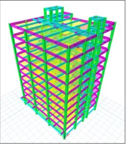
Fig -5: Isometric viеw ofstructure
3. RESULTS AND DISCUSSION
[image:3.595.45.570.65.619.2] [image:3.595.39.265.103.343.2] [image:3.595.309.565.306.599.2] [image:3.595.71.243.382.635.2]© 2015, IRJET ISO 9001:2008 Certified Journal
Page 1559
Table- 2:Comparison of composite and conventional (RC)building for base shear
STOREY LEVEL
BASE SHEAR ( kN ) %
increase of base
shear COMPOSITE CONVENTIONAL
LMR TOP 281.616 0 100
LMR
BOTTOM 776.5786 0 100
TERRACE 2566.665 349.305 86.39
8F 4777.847 737.262 84.56
7F 6755.505 1047.6 84.49
6F 8499.639 1288.98 84.83
5F 10010.25 1470.04 85.31
4F 11287.33 1599.46 85.82
3F 12330.9 1685.87 86.32
2F 13140.93 1737.93 86.77
FF 13717.45 1764 87.14
GROUND
FLOOR 14100.11 1774.75 87.41
PLINTH 14128.06 1774.98 87.43
Chart- 1: Comparison of composite and conventional (RC) building for base shear.
Base shear for composite building is observed to be 8 times higher than that of conventional building. Maximum base shear is observed in case of composite structures. From this it is noticed that conventional structure is safer.
Table- 3:Comparison of composite and conventional (RC) building for overturning moment
STOREY LEVEL
STOREY OVERTURNING MOMENT (MN-m)along X
direction increase %
COMPOSITE CONVENTIONAL
LMR TOP 0 0 0
LMR
BOTTOM 0.5913 0 100
TERRACE 1.5232 0 100
8F 9.7366 1.1177 88.52
7F 25.0257 3.4770 86.10
6F 46.6433 6.8293 85.35
5F 73.8422 10.9540 85.16
4F 105.875 15.6582 85.21
3F 141.994 20.7764 85.36
2F 181.453 26.1712 85.57
FF 223.504 31.7326 85.80
GROUND
FLOOR 267.4 37.3784 86.02
PLINTH 312.52 43.0576 86.22
BASE 333.713 45.7200 86.29
Chart- 2: Comparison of composite and conventional (RC) building for overturning moment
© 2015, IRJET ISO 9001:2008 Certified Journal
Page 1560
Table- 4: Comparison of composite and conventional (RC)building for storey drift.
STOREY LEVEL
STOREY DRIFT along X
direction %
increase COMPOSITE CONVENTIONAL
LMR TOP 0.00398 0.00052 86.93
LMR
BOTTOM 0.00406 0.000551 86.42
TERRACE 0.005007 0.00081 83.82
8F 0.007158 0.001231 83.80
7F 0.00927 0.001614 82.58
6F 0.01114 0.001916 82.80
5F 0.01272 0.002136 83.20
4F 0.01399 0.002282 83.68
3F 0.01493 0.002362 84.17
2F 0.015547 0.002377 84.71
FF 0.01530 0.002301 84.96
GROUND
FLOOR 0.01301 0.001959 84.94
PLINTH 0.005069 0.000762 84.96
BASE 0 0 0
Chart -3: Comparison of composite and conventional (RC) building for storey drift
Storey drift along both X and Y direction is maximum in 2Floor in composite building. In conventional building considerable difference is observed between the floors. More drift is observed in X direction when compared along Y direction.
Table- 5: Comparison of composite and conventional (RC) building for roof displacement.
STOREY LEVEL
DISPLACEMENT (mm) along X
direction %
increase COMPOSITE CONVENTIONAL
LMR TOP 394.6 62.7 84.11
LMR
BOTTOM 386.4 61.7 84.03
TERRACE 384.7 61.8 83.93
8F 368.7 59.2 83.94
7F 345.8 55.3 84.00
6F 316.1 50.1 84.15
5F 280.5 44 84.31
4F 239.8 37.1 84.52
3F 195 29.8 84.71
2F 147.2 22.3 84.85
FF 97.7 14.7 84.95
GROUND
FLOOR 48.7 7.3 85.01
PLINTH 7.6 1.1 85.52
BASE 0 0 0
Chart -4: Comparison of composite and conventional (RC) building for roof displacement
© 2015, IRJET ISO 9001:2008 Certified Journal
Page 1561
4. CONCLUSIONS
Analytical study has been conducted to understand the behavior of concrete encased columns in a structure. ETABS software is used to carry out the analysis. Comparison of conventional and composite design has done. And the following conclusion has been drawn from it.
Both the composite and conventional
buildings/structures which are comparatively studied, behave identically for the parameters considered, but more difference in their magnitudes.
It is observed that the base shear is about 80% difference in composite columns structure when compared to the structure with RC columns. Hence, conventional building can be considered superior than the composite building in terms of base shear.
From the comparative study made for a typical low rise building with a height of 36.8 m, the base shear is more in composite structure and so it is more vulnerable to earthquake than the RC building.
Storey drifts and overturning moments are also higher that is 80% and 85% in the case of composite building.
The storey drift is maximum at second floor which may cause more damage to the floors above it, particularly in case of composite structure. But in conventional building, not much drift are observed in between successive floors, which makes it relatively safe.
These results and comparative study observations lead to a conclusion that for low rise buildings composite column design is not suitable.
ACKNOWLEDGEMENT
I take this opportunity to express my sincere gratitude and profound thanks to my guide. I sincerely dedicate this thesis to my parents, husband and friends who were a constant source of inspiration and support in my life.
REFERENCES
1. C.C.Weng, S.I.Yen (2001).,"Comparisons of concrete-encased compositecolumn strength provisions of ACI code and AISC^specification", Department of Civil Engineering, National Chiao Tung University, Hsinchu, 30050, Taiwan, ROC. Engineering Structures 24 (2002) 59–72.
2. P. Valach, Š. Gramblička (2007),"Theoretical and experimental analyses of composite steel-reinforced concrete (SRC) columns" Slovak journal of civil engineering 2007/4 PAGES 1 – 9 RECEIVED 15. 5. 2007 ACCEPTED 20. 9. 2007.
3. Cheng-Chih Chen, Jian-Ming Li, C.C. Weng (2005)," Experimental behavior and strength of concrete-encased composite beam–columns with T-shaped steel section under cyclic loading" Journal of Constructional Steel Research 61 (2005) 863–881.
4. N.E. Shanmugam, B.Lakshmi (2001), "State of the art report on steel–concrete composite columns " Journal of Constructional Steel Research 57 (2001) 1041–1080.
5. Mahbuba Begum et al.,(2013),"cost analysis of steel concrete composite structures in Bangladesh" ASIAN JOURNAL OF CIVIL ENGINEERING (BHRC) VOL. 14, NO. 6 (2013) PAGES 935-944.
6. Prof. S. S. Charantimath et al.,(2014), "Comparative Study on Structural Parameter of R.C.C and Composite Building" Civil and Environmental Research ISSN 2224-5790 (Paper) ISSN 2225-0514 (Online).Vol.6, No.6, 2014.
7.Shweta A. Wagh & Dr. U. P. Waghe(2014), "Comparative Study of R.C.C and Steel Concrete Composite Structures" Journal of Engineering Research and Applications ISSN : 2248-9622, Vol. 4, Issue 4( Version 1), April 2014, pp.369-376.
8. Zafar Mujawar & Prakarsh Sangave (2015), "Comparative Evaluation Of Reinforced Concrete, Steel And Composite Structures Under The Effect Of Static And Dynamic Loads" Journal of Engineering Research and Applications ISSN : 2248-9622, Vol. 5, Issue 1( Part 5), January 2015, pp.41-44
9. Shashikala. Koppad & Dr. S.V.Itti (2013),"Comparative Study of RCC and Composite Multistoreyed Buildings" International Journal of Engineering and Innovative Technology (IJEIT) Volume 3, Issue 5, November 2013.
10. Holger Eggemann (2003) ,"Development of composite columns. Emperger's effort" Proceedings of the First International Congress on Construction History, Madrid, 20th-24th January 2003, ed. S. Huerta, Madrid: I. Juan de Herrera, SEdHC, ETSAM, A. E. Benvenuto, COAM, F. Dragados, 2003
11. D. R. Panchal and P. M. Marathe (2011), "Comparative Study of R.C.C, Steel and Composite (G+30 Storey)
Building" INSTITUTE OF TECHNOLOGY, NIRMA
UNIVERSITY, AHMEDABAD – 382 481, 08-10 DECEMBER, 2011
© 2015, IRJET ISO 9001:2008 Certified Journal
Page 1562
Applications (IJERA) ISSN: 2248-9622 www.ijera.com Vol.3, Issue 2, March -April 2013, pp.534-539
13. “ETABS–Integrated Building Design Software, User Interface Reference Manual”, Compu1ters and Structures, Inc. Berkeley, California, USA.
CODE OF PRACTICE:
1. IS 456: 2000, “Code of Practice for Plain and Reinforced Concrete”, Bureau of Indian Standards, New Delhi.
2. IS 800: 2007, “Code of Practice for General Construction in Steel”, Bureau of Indian Standards, New Delhi.
3. IS 1893: 2002, “Criteria for Earthquake Resistant Design of Structures – general provisions for buildings (Part-1)”, Bureau of Indian Standards, New Delhi, 2002.
4. Eurocode 4 (1994): Part 1.1, “Design of Composite Steel – Concrete Structures; General Rules and Rules for Buildings”.
BIBILOGRAPHY:
1. Composite column design to eurocode4 by Institute for steel development and growth.
2. Composite structures of steel and concrete by R.P. JOHNSON, volume I
BIOGRAPHIES
Hajira Nausheen
(PG Student, Department of civil engineering, U.B.D.T College of Engineering, Karnataka, INDIA)
Dr.H.Eramma