14th International Conference on Wireless Communications, Networking and Mobile Computing (WiCOM 2018) ISBN: 978-1-60595-578-0
The Method of Anti-Multipath for Recombination CDMA Users
Based on Chip Waveform Compensation
Qingwei Li, Xin Jin and Na Wu
Abstract: In cognition radio system, the technology using CDMA users with controllable spectrum nulls as cognitive user possess the advantage of both CDMA and cognition radio. The existing method to obtain controllable spectrum nulls for cognition CDMA is to use recombination sequence. The autocorrelation performance is turned out to lower through derivation and analysis, which result in the lower of anti-multipath performance of CDMA users with recombination sequence through giving the variance of decision variables at the Rake receiver for asynchronous DS-CDMA system in Rayleigh fading channel. Moreover, the performance of anti-multipath for CDMA users depended on both chip waveform and spread-spectrum sequence. Thus, the performance of anti-multipath for CDMA users can be compensated by introducing chip waveform with satisfactory autocorrelation performance. The amendatory Hermite function (AHF) was turned out to possess
1
properties of fine autocorrelation and cross-correlation, energy concentration in time and frequency domain, which turned out to be appropriate to compensate the anti-multipath performance of CDMA users with recombination sequence. What is more, the spectrum nulls of AHF change when the order changes. It means that only the order of AHF used by CDMA users need to be changed when the frequency band of interference or authorized users change. It was turned out that the bit error rate (BER) performance of recombination CDMA users with AHF outweighed that with classic waveforms whenever there were multiple-access interference (MAI), multiple-path interference(MPI), narrow band interference(NBI). The proposed method possesses better performance of anti-MAI, anti-MPI, anti-NBI.
Keywords: spectrum null; chip waveform; amendatory Hermite function; anti-multiple multipath interference; anti- narrow band interference
1. INTRODUCTION
radio, it can effectively reduce the interference of cognitive users to authorized users while guaranteeing the communication performance of cognitive users themselves. Through the combination of the two technologies, a new cognitive wireless communication system, the spectrum controlled cognitive CDMA communication system, can be constructed. In this communication system, the traditional method is mainly based on the design of composite sequence, and the mW composite sequence constructed by M and Walsh sequence is used as the spread spectrum sequence, so that the composite CDMA user presents a certain spectrum zero filling characteristic [3-5]. However, the anti-multipath performance of the composite CDMA users in the actual fading channel has not been analyzed. In addition, one of the applications of CDMA communication is to make use of the orthogonal multiple access characteristics of spread spectrum code, while the CDMA user's multiple access performance is not analyzed when using compound sequence. Moreover, the existing spectrum controlled cognitive CDMA communication system is only designed from the spreading sequence itself, while the waveform adopted for chip symbols has not been considered. [6-7] points out that the BER performance of users with different chip symbol waveforms is different in multipath channel. And [8-9] propose the user uses different chip symbol waveforms, and the bit error rate performance is different under multiple access interference. [10] shows that by designing the chip symbol waveform, it can make the spread spectrum user transmit a certain spectrum zero filling characteristic. If a suitable chip symbol waveform is designed or selected, it is possible to improve the anti-multipath, anti-multiple access and spectrum zero filling characteristics of the composite CDMA users.
2. CDMA SYSTEM MODEL USING RAKE RECEIVER IN FADING
CHANNEL
Suppose that a CDMA system has a total of Kusers, carrier frequency fc and 2π
c fc
, the length of the spread spectrum sequence is N , the chip width is Tc,
each source uses a spread spectrum sequence cycle and the source width isT NTc.
CDMA system emitter signal
1
cos K
k c
k
S t s t t
(1)The baseband signal of thek user
k k k c
n
s t b n N c n g t T n
(2)where {𝑏𝑘[𝑚] ∈ {−1,1}}𝑚=−∞∞ represents the source data sent by a k user;
{𝑐𝑘[𝑛] ∈ {−1,1}}𝑛=0𝑁 denotes a spread spectrum sequence used by a k user;
c
g t T represents the chip waveform, which is generally a real signal in the actual
For the CDMA signal, the spectrum of the transmitted signal is greater than the Doppler shift in the actual communication system. Therefore, it is possible to set CDMA signals to be slow fading in multipath channel transmission, that is, within a source symbol transmission time interval, we can assume that each path's fading, additional phase shift and delay are relatively unchanged. For the L multipath
channel, the channel impact response of the k user can be expressed as
,
1 , , 0 k l L jk k l k l
l
h t e T
(3)Where {𝛼𝑘,𝑙}𝑙=0𝐿−1、{𝜃𝑘,𝑙}𝑙=0𝐿−1 and {𝑇𝑘,𝑙}𝑙=0𝐿−1 represent the attenuation of the L path of
the k user, the additional phase and the delay, respectively, And they are independent
of each other. {𝛼𝑘,𝑙}𝑙=0𝐿−1 is determined by the type of the actual fading channel,{𝜃𝑘,𝑙}𝑙=0𝐿−1 and {𝑇𝑘,𝑙}𝑙=0𝐿−1 is uniformly distributed random variable., {𝜃𝑘,𝑙}𝑙=0𝐿−1
is evenly distributed in 0 2π,{𝑇𝑘,𝑙}𝑙=0 𝐿−1
is evenly distributed in 0 T. At the same
time, considering the multipath and multiuser, the signals received by the CDMA system is
1 , ,
,
,
,
1 0
cos K L
k l k l k l c k l k l k l
r t S t h t n t s t T t T n t
(4)Where n t
is a band limited Gauss white noise, and the bilateral power spectral density is n0 2。Support 𝜏𝑘,𝑙 = 𝑇𝑘,𝑙⁄𝑇𝑐,then
, , ,
k l k l k k c k l
n
s t T b n N c n g t T n
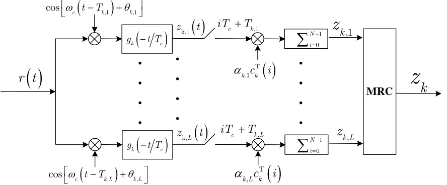
(5)For the DS-CDMA system, due to the short time interval between the chip symbols, the resolution of the distinguishable multipath is discussed here. At the receiving end, a reception decision can be performed using the maximum ratio of Rake receivers as shown in Fig. 1.
As shown in Figure 1, it represents the K user, using the schematic diagram of the Rake receiver of the MRC. Considering the identity of multiuser, this is discussed in the case of first users' reception decisions. And the reference path of the selected first users is lr, without losing its generality, assuming the delay of the selected reference
path 1, 0
r
l
T and the additional phase shift 1, 0
r
l
of the reference path. According to
figure 1, the output of the first waveform matching of the reference path of the first users is
1, '1, 1 1
1 1
1, 1, 1 1,
0, 0 1 1 2 cos 2 cos r r r l c l c n L N c
l l c l
l l l n
K L N
c
T
Z t u t b n N c n g t T n
T
c n g t T n
T
c n g t T n
Where k l, c k lT, k l, ; '
u t is the filtered Gauss white noise. Without losing
generality, the zeroth source decisions of first users are selected here.
k c
g t T
,1
c k
iT T
k,1 z t
T ,1k ck i
1 0 N i
z
k,1
r t
.
.
.
.
.
.
.
.
.
.
.
.
MRC
,1
,1cosc t T k k
k
z
k c
g t T
,
c k L
iT T
k,L z t
T ,k L kc i
1 0 N i
z
k L,
, ,
[image:4.612.102.546.131.315.2]cos c t Tk L k L
Figure 1. Schematic diagram of Rake receiver for user.
' 1 1,1, 1 1 1,
0 '
1,
1 1
1, 1, 1
0,l 0 1, , 1 , , 0 0
Z 0 ... ...
2 1 1 cos ... 2 1 cos ... 2 1 r r r N l c l l n c l L N c l l
l l n
l k l L
c
k l k l k l
n g n
T
b n N c n
n N T g N n
g n T
c n
g N n
g n T c n g N
1 2 0 , K N k n k l n
(7)The decision variable of first users receives 0-th sources on the reference path [11].
k
r
1, 1, 1 1, 1,
2
1, ''
1
1 1
1,
1, 1, 1 1 1,
0, 0
1 1
1,
1, 1, 1 ,
2 0 0
0 C 0 Z 0
0 0 2 cos 2 cos 2
r r r
r
r
r
r
T
l l l l
l b
L N
l c
l l l
l l l s n
K L N
l c
l l k k l
k l s n
z Z
E
b u
T
c n s c n g s
T
c n s c n g s
(8)
c
c
dg s g t T g t T s t
is the autocorrelation of the waveform function,
1
0
N
k k k
n
r s c n c n s
indicates the k-th user’s the autocorrelation function of thespread spectrum sequence,
1
,
0
N
k i k i
n
r s c n c n s
represents the cross correlationfunction for k and i sequences of user spread spectrum.
2 1
1, '' 1,
1, 1 1, 1, 1 1,
0,
1 1,
1, 1, 1, ,
2 0
0 0 0 cos
2 2 cos 2 r r r r r L
l b l c
l l l l
l l l s
K L l c
l l k k l
k l s
E T
z b u r s g s
T
r s g s
(9)For single waveform CDMA users, the autocorrelation of spread spectrum signal affects the ability of anti-multipath interference (MPI), that is, the correlation between the autocorrelation and the waveform of the sequence affects the ability of anti-multipath interference; The cross correlation of spread spectrum signals affects the ability of CDMA users to suppress MAI, that is, the autocorrelation of sequence correlation and waveform determines its ability to suppress MAI. Therefore, the second item of the upper Eq contains the waveform autocorrelation and the sequence autocorrelation of the reference user, so it is a multipath interference (MPI) item; The third item, which includes the cross correlation between the reference user and the rest of the user sequence, and the autocorrelation of the reference user and the rest of the user using the symbol waveform, .are therefore the multipath interference (MAI) item.
Let ΓMPI(𝜏1,𝑙) = ∑∞𝑠=−∞𝑟1(𝑠)ĝ(𝑠 − 𝜏1,𝑙),which represents the interference value associated with the multipath, ΓMAI(𝜏𝑘,𝑙) = ∑∞𝑠=−∞𝑟1,𝑘(𝑠)ĝ(𝑠 − 𝜏𝑘,𝑙) represents the interference values associated with multiple access.
2 1
1, '' 1,
1, 1 1, 1, MPI 1,
0,
1 1,
1, 1, MAI ,
2 0
0 0 0 cos
2 2 cos 2 r r r r r L
l b l c
l l l l
l l l K L
l c
l l k l
k l
E T
z b u
2 2 1
2 1
0 1, 1, 0 2 1, 0 2
1, MPI 1, MAI ,
0, 2 0
var 0
4 4 4
r r r
r
r
L K L
l b b c l b c l
l l k l
l l l k l
N E E T E T
z
(11)
It can be seen from [11] that the SNR is inverse to var{𝑧1,𝑙𝑟[0]} when
E{𝑧1,𝑙𝑟[0]} is certain. In order to improve the signal o noise ratio, the vvar{𝑧1,𝑙𝑟[0]}
should be reduced as much as possible.
3. MULTIPATH INTERFERENCE ANALYSIS OF mW COMPOSITE
SEQUENCE SPREAD SPECTRTUM
Assume that the sequence length of the mW composite sequence is , the
length of the Walsh sequence is . The length of the compound sequence is
, which is expressed as follows
k 0, , 1k
s j m j W j ,j N (12)
The sequence consists of repetitions of each value of the sequence
. is periodic prolongation of the Walsh sequence . The
autocorrelation function of the is
1
0
N m
j
r l m j m j l
(13)The autocorrelation function of the is
mW 1
0
L m
j
r l m j m j l
(14)The autocorrelation function of sequence set is expressed as
mW 1
0 k
L W
k k
j
r l W j W j l
(15)The autocorrelation function of the composite sequence is
m lm
lw
*
N lm lw
m j lw m
m j
Wk
j
lm
W jk
m j
m j
Wk j
mW
mW
1
0
1 1
0
0 0
0 k
L
k k k
j
L M
k k
j w
W m
r l s j s j l
m j M m j l M W w W w l
r l M r l
(16)Where represents rounding operation, 。
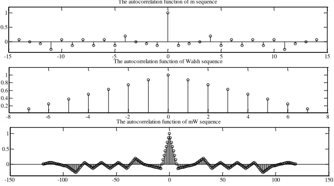
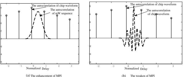
From the above formula we know that, the autocorrelation function of mW composite sequence is equivalent to the convolution of autocorrelation function of m sequence and Walsh sequence after drawing the autocorrelation function. In the case of relative determination of the autocorrelation of the m sequence, the autocorrelation of the composite sequence mainly depends on the autocorrelation of the Walsh sequence. The simulation results of Figure 2 verify the above analysis. At the same time, from Figure 2, it can be seen that the autocorrelation main lobe of the composite sequence extends relative to the m sequence because of the repeated moving of the Walsh sequence. For the conventional waveform [12], as shown in Figure 3 (a), the
length of the waveform autocorrelation continues 2Tc. Compared with the m sequence,
the composite sequence will undoubtedly increase the MPI in the Eq. (10), which leads to the increase of the variance of the decision variable of (11). Therefore, when the chip code waveform has good autocorrelation characteristics, as shown in Figure 3
(b), the waveform autocorrelation main lobe is small enough to make MPIclose to 0
[image:7.612.138.467.433.616.2]and reduce the multipath interference to the greatest extent.
Figure 2. Comparison of autocorrelation functions between mW composite sequence and m sequence.
l0 mod ,
l lw-15 -10 -5 0 5 10 15
0 0.5 1
The autocorrelation function of m sequence
-8 -6 -4 -2 0 2 4 6 8
0.2 0.4 0.6 0.8 1
The autocorrelation function of Walsh sequence
-150 -100 -50 0 50 100 150
0 0.5 1
-2 -1 0 1 2 3 -6
-4 -2 0 2 4 6 8
(b)
-2 -1 0 1 2 3
-6 -4 -2 0 2 4 6 8
(a)
Normalized Delay The enhancement of MPI
Normalized Delay The weaken of MPI The autocorrelation
of mW sequence The autocorrelation of chip waveform
[image:8.612.138.516.59.218.2]The autocorrelation of chip waveform The autocorrelation of chip waveform
Figure 3. Influence of different waveforms on multipath interference
4. CHIP WAVEFORM BASED ON AMENDATORY HERMITE
FUNCTION
The modified Hermite function (AHF) is represented as follows:
2 2
4 d 2
1 e e
d
t n t
n
n n
h t
t
(17)
Then
( )e 42t n n
h t p t (18)
Where ( )n
p t represents the n sub polynomial with maximum powert. As
2
4
e
t
is
the exponential decay factor, with the increase of n, AHF has been expanded, but
the energy is still concentrated, which determines that its function can be used as
the time domain waveform of the code element. Figure 4 (a) confirms the time
domain energy concentration characteristic of AHF. Eq.(17) can be further obtained.
2 24π
0 2 πe
f
H f (19)
1
1
j j2π
4π
n n n
2
1
j8π fHn f jHn f 4πnHn f
(21)
Since is still contained after multiple derivation . From (19) and (20),
can be expressed as
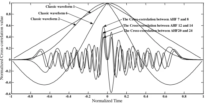
(a) The wave form of AHF with different orders
(b) The correlation comparison between AHF and conventional waveform
2 2
4π
e f e4π2f2
n
H f
-0.75 -0.5 -0.25 0 0.25 0.5 0.75
-0.1 -0.05 0 0.05 0.1 0.15
Normalized Time
N
orm
a
li
z
e
d A
m
pl
it
ude
The 0th AHF The 5th AHF The 10th AHF
The 15th AHF
The 20th AHF
-1 -0.8 -0.6 -0.4 -0.2 0 0.2 0.4 0.6 0.8 1
-0.6 -0.4 -0.2 0 0.2 0.4 0.6 0.8 1 1.2
Normalized Time
N
orm
a
li
z
e
d A
ut
oc
orre
la
ti
on F
unc
ti
on va
lue The 0th AHF
The 5th AHF
The 10th AHF The 15th AHF The 20th AHF
Classic waveform5 Classic waveform6
Classic waveform1
Classic waveform2
Classic waveform5
(c) The AHF and square wave of different order are compared with each other
Figure 4. Different order AHF, autocorrelation and interlocking characteristics.
2 2
4π
2 πe f
n n
H f X f (22)
Among them, 𝑋𝑛(𝑓) is a polynomial containing , and can be calculated by (19) and (20), the highest power in 𝑋𝑛(𝑓)is .Therefore, for 𝐻𝑛(𝑓), because of the presence of factors, 𝐻𝑛(𝑓) can also rapidly attenuate, and with the increase of , the
spectrum expands, but the expansion is limited. This also means that the higher the order of AHF, the higher the energy spectrum is, the more the corresponding autocorrelation function should be. Figure 4 (b) illustrates this inference. The good mutual correlation between AHF has been given in [13], as shown in fig.4 (c).
Can be seen from the figure 4 (a), AHF has good convergence time domain features, figure 4 (b) it can be seen that AHF autocorrelation characteristic is better than the conventional waveform, and, with the increase of order autocorrelation characteristic of AHF is getting better and better. As can be seen from fig.4 (c), the mutual correlation of AHF is better than that of conventional waveforms, and the mutual correlation of AHF is getting better and better with the increase of order.
Substituting equation (22) into equation (20) and (21) respectively
1
j
j4π 4π
n n n
X f X f fX f (23)
1 j4 1
n n n
X f fX f nX f (24)
j4π 1
n n
X f nX f (25)
Order , then , , And equation (24) can be further
expressed as
-1 -0.8 -0.6 -0.4 -0.2 0 0.2 0.4 0.6 0.8 1
-0.6 -0.4 -0.2 0 0.2 0.4 0.6 0.8 1
Normalized Time
N
orm
a
li
z
e
d Cro
ss
-c
orre
la
ti
on va
lue
Classic waveform 1
Classic waveform 6
Classic waveform 2 The Cross-correlation between AHF 7 and 8
The Cross-correlation between AHF 12 and 14 The Cross-correlation between AHF20 and 24
f
n
n
4π
1
1
2
n n n
X f YX f n X f (26)
It can be inferred from (26) that when it is even,
22 0
n n
n n
X f Y e Y e (27)
When it's odd,
1 3
2 1
n n
n n
X f Y Y c Y c (28)
According to the recurrence relation of (26), the coefficients in equation (27) and
(28) are real, and there are , ,
, The equations that can be constructed from the
formula (27) and (28) can be obtained
2
2 0 0
n n
n
Y e Y e (29)
1 3
2 1 0
n n
n
Y Y c Y c (30)
[image:11.612.91.508.430.719.2]There are pure imaginary roots of conjugate, and equation (29) exists for the conjugate imaginary root, and equation (30) has zero roots and the imaginary number conjugate root, and the largest imaginary number root.
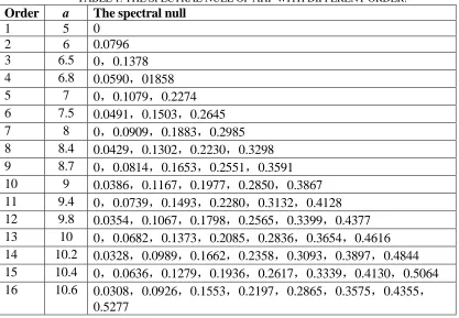
TABLE 1. THE SPECTRAL NULL OF AHF WITH DIFFERENT ORDER.
Order a The spectral null
1 5 0
2 6 0.0796
3 6.5 0,0.1378
4 6.8 0.0590,01858
5 7 0,0.1079,0.2274
6 7.5 0.0491,0.1503,0.2645
7 8 0,0.0909,0.1883,0.2985
8 8.4 0.0429,0.1302,0.2230,0.3298
9 8.7 0,0.0814,0.1653,0.2551,0.3591
10 9 0.0386,0.1167,0.1977,0.2850,0.3867
11 9.4 0,0.0739,0.1493,0.2280,0.3132,0.4128
12 9.8 0.0354,0.1067,0.1798,0.2565,0.3399,0.4377
13 10 0,0.0682,0.1373,0.2085,0.2836,0.3654,0.4616
14 10.2 0.0328,0.0989,0.1662,0.2358,0.3093,0.3897,0.4844
15 10.4 0,0.0636,0.1279,0.1936,0.2617,0.3339,0.4130,0.5064
2 4 2
0en en e e0
e2 2
22 4 1
0cn cn c
2
1 3 2
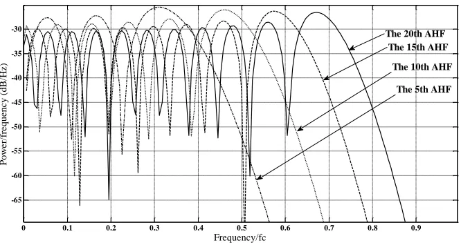
Figure 5. Power spectrum of different AHF.
The modulus is increasing. It can be seen from that, with the
increase of the number of AHF, the number of frequency points of is
increasing, that is, the number of AHF spectrum is increasing, and the zero-sink frequency point is gradually increasing. Composite spread spectrum will make CDMA user transmit signal have certain spectral zero-sink characteristics, but as chip code element waveform, AHF will increase the spectrum zero limit. As the order of AHF increases, the number of spectral zeros increases further. This is very useful for the anti-interference of the actual CDMA system. For the AHF with
continuous width of , as shown in table 1, the time domain value and
spectral zero value of AHF are given. The simulation results of table 1 and figure 5 show that the above analysis is well verified, that is, with the increase of the order, the time domain converges and the spectral zero increases. It is important to note
that when the initial AHF time domain 𝑡𝐻 = −𝑎~𝑎 is used, the time-domain
duration of compression to a chip element is 𝑡 = 0~𝑇𝑐.
There are
0
0
0.5 = 0.5
2 2
c
c c
t T
t T t T
a a
(31)
The corresponding frequency domain has
H*2 * c
f f a f (32)
When the initial AHF spectral zero is obtained as , the zero point of the chip code element that is actually adopted after compression is 𝑓 = 𝑓𝐻∗ 2𝑎 ∗ 𝑓𝑐, and
after normalization: 𝑓 𝑓⁄ 𝑐 = 𝑓0 ∗ 2𝑎.
0 0.1 0.2 0.3 0.4 0.5 0.6 0.7 0.8 0.9
-65 -60 -55 -50 -45 -40 -35 -30
Frequency/fc
P
ow
e
r/
fre
que
nc
y (dB
/H
z
)
The 20th AHF The 15th AHF The 10th AHF
The 5th AHF
4π
Y j f
0n
X f
a a
a
H
5. EXPERIMENTAL SIMULATIONS
Simulation conditions: composite cognitive CDMA users adopt mW composite sequence. In the composite sequence, m adopts 15 random sequences and Walsh adopts 8 bits. Multi-path channel uses Rayleigh fading channel, and the distribution of
scatterer adopts geometric SLR elliptical model. Path reflection loss 𝐿𝑟 = 4𝑑B, path
loss index n3dB. The user delays are evenly distributed at 0 ~T.T is the source
interval, the additional phase is evenly distributed at 0 ~ 2π . The receiver uses Rake
receiver. The interference in communication is multi-path interference, and the interference from other systems is narrow-band interference. g1(𝑡)、g2(𝑡)、g6(𝑡) in
the[12] are selected as the representative of conventional waveform. Moreover, g6(𝑡)
has the best self-correlation in the seven classical waveforms, which is of reference significance. AHF adopts the 10th order AHF. According to formula (32) and table 1, it can be calculated that the zero depression of the 10th order AHF in the 0~𝑓𝑐 frequency band is 𝑓 = 0.0386 ∗ 2 ∗ 9𝑓𝑐 = 0.69𝑓𝑐. Therefore, the frequency of the
narrow-band interference center constructed is 0.69𝑓𝑐 and the bandwidth is 0.2𝑓𝑐.
Letter dry ratio Eb⁄EI= −20𝑑B.
[image:13.612.128.455.371.613.2](1) Under the Rake receiver, a single random paths, the comparison of the BER performance[14] of five composite cognitive user with AHF and conventional waveform under MAI.
Figure 6. The user’s BER performance comparison use AHF and regular waveform MAI.
The simulation results of fig.6 show that, compared with the classical waveform, users can effectively improve the error rate performance of their multi-site interference
14 15 16 17 18 19 20
10-4 10-3 10-2
Eb/n0(dB)
BE
R
g
1 (t)
g
2 (t)
g
6 (t)
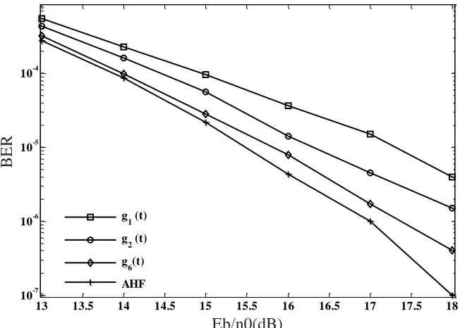
(2) Under the Rake receiver, 3 random paths, the comparison of the BER performance of a single composite cognitive user with AHF and conventional waveform under MPI.
Figure 7. The user’s BER performance comparison use AHF and regular waveform MPI.
The simulation results of fig.7 show that, compared with the classical waveform, users can effectively improve the error rate performance of their multi-path interference with AHF.
(3) Under the Rake receiver, a single random paths, the comparison of the BER performance of a single composite cognitive user with AHF and conventional waveform under the narrow band interference (NBI).
13 13.5 14 14.5 15 15.5 16 16.5 17 17.5 18
10-7 10-6 10-5 10-4
Eb/n0(dB)
BE
R
g
1 (t)
g
2 (t)
g
6(t)
Figure 8. Comparison of BER performance between AHF and conventional waveform under NBI.
The simulation results of figure 8 show that, compared with the classical waveform, the user can effectively improve the BER performance of the narrowband interference with AHF, which also verifies the previous theoretical analysis that using AHF's composite users, the spectrum of the transmitting signal can effectively form zero filling in the interference, thus effectively avoiding interference and improving BER performance.
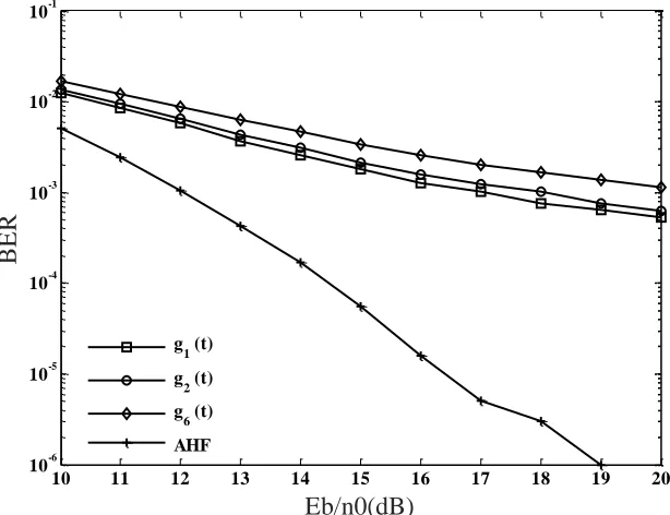
(4) Three random paths, five compound cognitive users, using AHF and
conventional waveform in multiple access and multipath interference (MAI+MPI), The comparison of BER performance of optimum receiver and Rake receiver respectively.
Figure 9 of the simulation results show that, compared with the classical wave, complex user using AHF, under the multiple access, multipath interference, BER performance improvement is more noticeable, this is because the user use the AHF, multiple access and anti-multipath performance while increasing resistance. Therefore, the BER performance of AHF users must be further improved when there are multiple paths and multiple access disturbances at the same time.
10 11 12 13 14 15 16 17 18 19 20
10-4 10-3 10-2 10-1 100
Eb/n0(dB)
BE
R
g
1 (t)
g
2 (t)
g
6 (t)
Figure 9. Comparison of BER performance between AHF and conventional waveform under MAI+MPI.
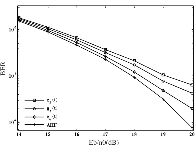
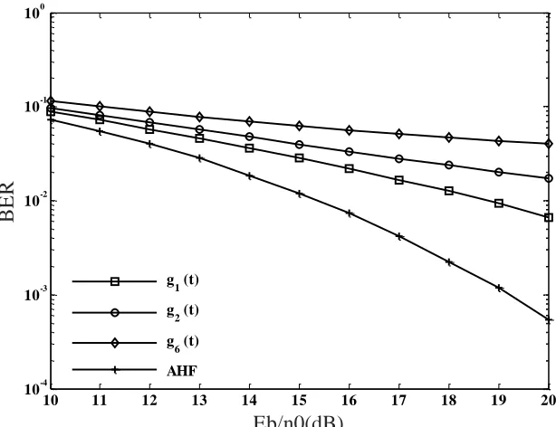
(5) In the Rake receiver, when 5 composite users, 3 random paths and narrow-band
interference coexist, comparison of BER Performance of composite cognitive users using AHF and regular waveforms.
Figure 10. Comparison of BER performance of composite users using AHF and conventional waveforms at MAI+MPI+NBI.
10 11 12 13 14 15 16 17 18 19 20
10-4 10-3
Eb/n0(dB)
BE
R
g
1 (t)
g
2 (t)
g
6 (t)
AHF
10 11 12 13 14 15 16 17 18 19 20
10-6 10-5 10-4 10-3 10-2 10-1
Eb/n0(dB)
BE
R
g
1 (t)
g
2 (t)
g
6 (t)
[image:16.612.138.445.415.651.2]The simulation results in Fig. 10 show that when multiple access, multi-path, and narrow-band interference exist at the same time in actual communication, compared to classical waveforms, the composite user using AHF has significantly improved BER performance. This is also a good example of verifying that when a hybrid user adopts AHF, it can effectively improve its ability to resist multi-access, multi-path, and anti-narrow-band interference. This was confirmed by Figure 6, Figure 7, and Figure 9, respectively.
6. CONCLUSION
This paper analyzes and deduces the variance of decision variables under the Rake receiver for complex cognitive CDMA systems over Rayleigh fading channels. Further analysis of the autocorrelation property of the composite sequence indicates that the reduced autocorrelation of the composite sequence will lead to a decrease in the anti-multipath capability of the compound cognitive CDMA user. Through derivation and analysis, the autocorrelation of complex cognitive CDMA users can be compensated using a waveform with good autocorrelation. To this end, AHF was introduced. AHF has good autocorrelation, cross-correlation, and spectral nulling characteristics. When the composite cognitive CDMA user uses AHF as a chip symbol waveform, it can effectively improve its resistance to multi-path, multiple access, and narrow-band interference. Experimental simulations confirm that different orders of AHF have different spectral zeros, and as the order increases, the number of spectral zeros increases; At the same time, the BER performance of the composite cognitive CDMA user chip symbol using AHF and the classical waveform in five cases of MAI, MPI, NBI, MAI+MPI, MAI+MPI+NBI is compared. The simulation results show that the proposed composite cognitive CDMA system based on AHF has better BER performance than the classical cognitive CDMA system.
REFERENCES
1. S Haykin.2005. “Cognitive radio: Brain-empowered wireless communications,” J. IEEE Journal on Selected Areas in Communications, 23(2):201–220.
2. Y Lin, K Liu, and H Hsieh. 2013. “On Using Interference-Aware Spectrum Sensing for DSA in CR Networks,” J. IEEE Transactions On Mobile Computing, 12(3):461-474.
3. L. L. Guo, J.Z. Fu, H.Q. Cui and et al.2010. “Using m-Walsh composite sequences to reduce narrow-band interference in direct sequence spread spectrum systems,” J. Journal of Harbin Engineering University, 31(5): 646-651.
4. J.Z. Fu, L. L. Guo, H.Q. Yang.2010. “Performances of Mary orthogonal code spread spectrum system based on composite sequences,” J. Systems Engineering and Electronics, 32(4): 703-706. 5. L. L. Guo, X.P. Liu, J.Z. Fu and et al.2015. “Controllable composite sequence of power spectral
density based on the block coded signal,” J. Journal of Harbin Engineering University, 36(2): 248-251.
6. E Qzturk.2007. “Performance analysis of asynchronous direct sequence code division multiple access for general chip waveforms over multi-path Rayleigh fading channels,” J. IET Communications, 1(4): 570-576.
8. Tao Luo, P Subbarayan, and S S Elvino.2002. “Interference Control and Chip Waveform Design in Multirate DS-CDMA Communication Systems,” J. IEEE Transactions on Wireless Communications, 1(1):56-66.
9. Ha H Nguyen.2004. “An Improved Design of Chip Waveforms for Band-Limited DS-CDMA Systems,” J.IEEE Transactions on Vehicular Technology, 33(5):1379-1386.
10. L. L. Guo, Q. W. Li, F. Gao, et al. 2016. “A New Method of Generating Spectral Nulls at the Transmitter in Cognitive Radio,” J. Wireless Personal Communications, 88(4):819-837.
11. E. Ozturk.2007. “Performance analysis of asynchronous direct sequence code division multiple access for general chip waveforms over multi-path Rayleigh fading channels,” J. IET Commun., 1(4):570-576.
12. H. H. Nguyen, E. Shwedyk.2004. “Double chip waveforms for asynchronous DS-CDMA systems with random signature sequences,” J. IEE Proc Commun, 151(4):364-374.
13. L. L. Guo.1998. “Communication Mode of Composite Sequence Spread Spectrum with DS/FH Spectrum Feature,” J. Journal of Harbin Engineering University, 19(4):24-30.