A Virtualised Routing Protocol for Improving
Network Lifetime in Cluster Based Sensor
Networks
Ruslan Saad Abdulrahman Al-Nuaimi
College of Science and Technology
School of Computing, Science and Engineering
University of Salford, Manchester, UK
Submitted in Partial Fulfilment of the Requirements of the
Degree of Doctor of Philosophy
i
Table of Contents
Table of Contents ……….. i
List of Figures ……….. viii
List of Tables ……… xii
List of Pseudo Codes ………. xiii
Acknowledgements ……….. xiv
List of Abbreviations ………. xv
Abstract ………. 1
Chapter One: Introduction
2 1-1 Introduction ……… 21-2 Network Function Virtualisation (NFV) ……… 4
1-3 Research Problem ………... 5
1-4 Research Question……….. 8
1-5 Research Aims and Objectives ……… 8
1-6 Contribution of the thesis ……… 9
1-7 Research Process ………. 10
1-8 Thesis Layout ……….. 14
Chapter Two: An Overview of Wireless Sensor Networks
16 2-1 Wireless Sensor Networks Background ……… 162-2 Wireless Sensor Networks Characteristics ……….. 18
2-3 Sensor Nodes Architecture ……….. 21
2-4 Wireless Sensor Network Applications ……….. 22
ii
2-6 Routing Protocols in WSN ……… 26
2-6-1 Design Requirements for WSN Routing Protocols ………. 28
2-6-2 Classification of Routing Protocols in WSN ……… 30
2-6-2-1 Network structure-Based Routing Protocols ……… 31
I. Flat Routing Protocols Routing Protocols ……… 31
II. Hierarchical Routing Protocols Routing Protocols ……….. 31
III. Location-Based Protocols Routing Protocols ……….. 31
2-6-2-2 Protocol Operation-Based Routing Protocols ………. 32
I. Query-Based Routing Protocols ……….. 32
II. Multipath-Based Routing Protocols ……… 32
III. Negotiation-Based Routing Protocols ………. 32
IV. QoS Based Routing Protocols ….……….. 33
V. Non-Coherent and Coherent Based Routing Protocols ….……… 33
2-6-2-3 Routes Establishment ……..………... 33
I. Proactive Routing Protocols ………. 34
II. Reactive Routing Protocols ……….. 34
III. Hybrid Routing Protocols ………. 34
2-7 Energy Consumption in Wireless Sensor Networks ………... 35
2-7-1 Sensor Node and Network Lifetime ………... 40
2-8 Summery ……… 41
iii
3-2 The Clustering Approach ……… 42
3-4 Clustering Based Routing Protocols ………..….… 50
3-4-1 Distributed Clustering Protocols ……….. 51
1- LEACH Low-Energy Adaptive Clustering Hierarchy (LEACH) …… 52
2- LEACH-Balanced (LEACH-B)……… 56
3- Extended-LEACH (E-LEACH) ………. 57
4- Energy-Efficient LEACH (EE-LEACH) ……….. 57
5- Energy Efficient Extended LEACH (EEE LEACH) ……… 57
6- Power-Efficient Gathering Sensor Information Systems (PEGASIS) ... 58
7- PEGASIS-LEACH ……….. 58
8-Threshold sensitive Energy Efficient Sensor Network Protocol (TEEN). 58 9-Adaptive Periodic-TEEN (APTEEN) ……….. 59
10-LEACH-Selective Cluster (LEACH-SC)………. 59
11- Narrative-LEACH ……… 59
12-Two Level (TL-LEACH) ……… 60
13- Double Cluster Based Energy Efficient Routing Protocol ………….. 60
14-Cognitive LEACH ……….. 61
15- Solar LEACH (SLEACH) ……….. 61
16- Hybrid Energy-Efficient Distributed Clustering Protocol (HEED)….. 61
17-Unequal Cluster-based Routing protocol (UCR) ……….. 62
18- Centralised Energy Efficient Distance Protocol (CEED) …………... 62
19-Unequal Clustering Routing for Mobile Education Protocol ……….. 63
20-Double-phase Cluster-head Election Clustering Protocol (DEC) …… 63
iv
3-4-2 Centralised Clustering Protocol ………... 64
1- Centralized LEACH (LEACH-C) ………. 65
2- Modified LEACH-C ……… 67
3- LEACH Central Constrained (LEACH-CC) ……… 67
4- Energy Efficient LEACH-C (EELEACH-C) ……… 67
5- Base-Station Controlled Dynamic Clustering Protocol (BCDCP) …… 68
6- Centralised Genetic-Based Clustering (CGC) ……….. 68
7- Centralized Balance Clustering Routing Protocol ……….. 68
3-5 Critical Analysis ………. 76
3-6 Summary ………. 76
Chapter Four: A Virtualised Clustering Routing Protocol (VCR)
78 4-1 Introduction ………. 784-2 The Assumptions of the VCR ………... 78
4-3 VCR Protocol Functions ….……….. 81
4-3-1 Node Discovery Function ……….. 84
4-3-2 Information calculation Function ………... 86
4-3-3 Clustering Function ……… 90
4-3-3-1 Setup Stage (cluster formation and cluster head selection by NFV server) ……….. 90
Step 1- Calculate Optimum Number Of Clusters ………. 90
Step 2- Cluster Formation ……….. 92
Step 3- Cluster Head Selection ……… 97
v
4-3-3-3 Steady state stage (data transmission) ………..…… 99
4-3-4 Schedule Formation ………..……… 101
4-4 Energy Consumption Calculation Function ……….. 102
4-5 Cluster Head re-selection Function ………. 103
4-6 Re-Clustering Function ………. 105
4-7 Summary ……… 106
Chapter Five: The Developed Mathematical model for Virtualised
Clustering Routing Protocol (VCR)
108 5-1 Introduction ……… 1085-2 Radio Energy Model ……….. 108
5-3 Analysis of the Energy Consumption of the VCR……..……….. 110
5-3-1 Energy Consumption Model in Node Discovery (Broadcasting) ……… 112
5-3-2 Cluster Head (CH) node energy consumption per cycle ……….. 113
5-3-3 Non-Cluster Head (CH) energy consumption per cycle ……….. 114
5-3-4 Remaining energy level for CHs and Cluster members’ nodes ………… 116
5-3-5 Total network energy consumption per cycle ………. 117
5-3-6 Total network energy consumption per cycle ………. 117
5-4 Analysis of power consumption in the LEACH protocol ……… 117
5-4-1 Energy Consumption Model in Processing ……… 118
5-4-2 Energy Consumption Model for Cluster Head Node ………. 119
5-4-3 Energy Consumption Model for Cluster Member Node ……… 121
5-5 Summary ………. 123
vi
6-2 Experimental Design ……….……….. 125
6-2-1 Validation Experiments ……….……… 125
6-2-2 Evaluation Experiments ……….……… 126
6-3 Network Topology Setup ……… 127
6-4 Calculation of the Optimum Number of Clusters ……….. 129
6-5 Clusters Formation ……….. 130
6-6 Results and Validation ………. 131
6-6-1 Energy Consumption Calculation ………. 131
1- Experiment One: number of nodes 100, sink location 50,175 and sensing area size (100*100) ……….. 132
2- Experiment Two (change Sink Position and area size) ……… 133
3- Experiment Three (based on different number of clusters) ………… 135
3-1 Scenario One: When Number of Nodes=50 ……… 135
3-2 Scenario Two: When Number of Nodes=150 ……….. 136
3-3 Scenario Three: When Number of Nodes=200 ……… 137
4- Experiment Four: Various node density within the clusters (Different number of Nodes) ……… 138
5- Experiment Five: Scenario 5: Dynamic and Static clustering in VCR 139 6-7 Evaluation ………. 140
6-7-1 Experiment Six: Lifetime measurement based on First Node Dead (FND) 141 6-7-2 Experiment Seven: Start-up Cost ….……… 142
6-7-3 Experiment Eight: Round Rotation ……… 144
6-8 Results Analysis ……….. 145
6-9 Summary ………. 146
vii
7-1 Introduction ………. 149
7-2 Conclusions ………. 149
7-3 Future Works ……… 152
Publications ……… 154
References ………. 155
Appendix A: PDUs …………. ……… 169
Appendix B: Protocol Diagram ………. 177
Appendix C: Virtualised Clustering Routing (VCR) Protocol Flow Chart………… 178
Appendix D: Network Topologies ……… 179
viii
List of Figures
Figure (1-1) NFV Vision ……….. 5
Figure (1-2) Research Process ……… 10
Figure (2-1) Simple Diagram of a WSN ……….. 17
Figure (2-2) Sensor Node’s Architecture ………. 22
Figure (2-3) WSN Applications ………... 24
Figure (2-4) WSN Protocol Stack ……… 25
Figure (2-5) WSN Communications type ……… 27
Figure (2-6) Routing Protocols Classifications ……… 30
Figure (2-7) Energy Consumption Domains ……… 37
Figure (2-8) Sensing Component Modes ……… 38
Figure (2-9) Transceiver Component Mode ……… 38
Figure (2-10) Processing Component Mode ……… 38
Figure (3-1) Architecture of cluster-based routing protocols ……….. 43
Figure (3-2) Clustering Function Stages ……….. 44
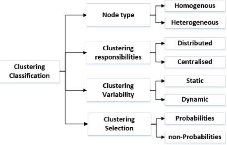
Figure (3-3) Clustering Proprieties ……….. 44
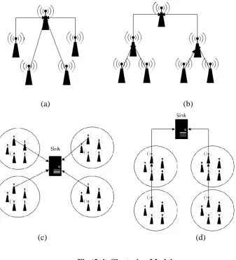
Figure (3-4) Clustering Model ………. 47
Figure (3-5) Clustering Timing ……….. 48
Figure (3-6) Clustering Routing Protocols classification ……… 50
Figure (3-7) Distributed Clustering Protocol Flowchart……… 51
Figure (3-8) LEACH round timeline ……….. 53
ix
Figure (3-10) LEACH communications fields ………. 55
Figure (3-11) Centralised Clustering Protocol Flowchart ……… 65
Figure (3-12) LEACH-C operation flow chart ………. 66
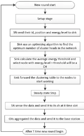
Figure (3-13) Proposed Protocol (VCR) operation flow chart ………. 77
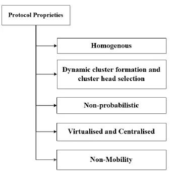
Figure (4-1) Virtual Clustering Routing Protocol Characteristics ……….. 80
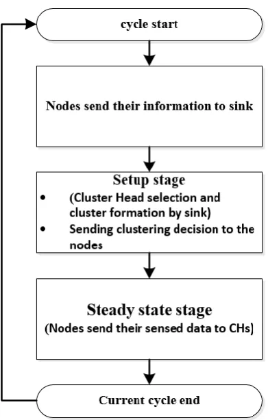
Figure (4-2) VCR Clustering cycle ……….. 82
Figure (4-3) VCR diagram.………. 83
Figure (4-4) VCR Communications Fields ………. 84
Figure (4-5) Node Discovery Function ………….……… …. 85
Figure (4-6) Node Discovery Packet (SN_Dis_PDU) ……… 85
Figure (4-7) Sink_Server_Discovery Packet (Sink_Server_Dis_PDU) ………. 85
Figure (4-8) Information Calculations Function ………. 86
Figure (4-9) Clustering Function ………. 90
Figure (4-10) K-means algorithm ………. 95
Figure (4-11) Cluster Formation Diagram ……….. 96
Figure (4-12) Server to Sink Cluster Information Packet (Cl_Inf_Server_sink_PDU) 98 Figure (4-13) Sink to Node Cluster Information Packet (Cl_Inf_Sink_Node_PDU) 99 Figure (4-14) Sensed Data Info (Sense_Data_Info) ……… 99
Figure (4-15) Aggregated Data Info (Agg_Data_Info) ………... 100
Figure (4-16) Steady state stage ……….. 100
Figure (4-17) Notification Packet (Notification_PDU) ……….. 101
Figure (4-18) Cluster Head re-selection Function……… 104
Figure (4-19) Cluster Head re-selection Packet (Reslect_CH_Packet) ……… 104
x
Figure (4-21) Re-Clustering Function ……… 106
Figure (5-1) Radio Energy Consumption Model (redraw from [1]) ……… 108
Figure (5-2) Energy Consumption Chart for VCR ……… 111
Figures (6-1) Network Topology Example ………. 128
Figures (6-2) K-means average convergence iterations ……….. 130
Figure (6-3) Average Energy Consumption with N=100 ……… 132
Figure (6-4) Average Energy Consumption with varying sink position……….. 134
Figure (6-5) Average Energy Consumption with different sensing area size……….. 135
Figure (6-6) Optimum Number of Clusters for N=50 ……….. 136
Figure (6-7) Optimum Number of Clusters for N=150 ……… 137
Figure (6-8) Optimum Number of Clusters for N=200 ……… 137
Figure (6-9) Average Energy Consumption with different nodes density ………….. 138
Figure (6-10) Static vs Dynamic Clustering in VCR ……….. 140
Figure (6-11) Comparison among VCR, LEACH and LEACH-C………. 142
Figure (6-12) Start-Up Energy Consumption ……….. 143
Figure (6-13) Static Proposed Protocol vs. Static LEACH ……….. 145
Figure (A-1) Type of Packet (ToP) …….……….. 169
Figure (A-2) General Packet Format ……….. 169
Figure (A-3) Node Discovery Packet (SN_Dis_PDU) ………... 170
Figure (A-4) Sink_Server_Discovery Packet (Sink_Server_Dis_PDU) ……… 170
Figure (A-5) Server to Sink Cluster Information Packet (Cl_Inf_Server_sink_PDU).. 171
xi
Figure (A-8) Aggregated Data Packet (Agg_Data_PDU) ……… 174
Figure (A-9) End Cycle Notification Packet (End_Cycle_notify_PDU) ………. 174
Figure (A-10) Cluster Head re-selection Packet (Reslect_CH_Server_Sink_Packet).. 175
Figure (A-11) Cluster Head re-selection Packet (Reslect_CH_Sink_Node_Packet)… 175 Figure (C-1) Virtualised Clustering Routing (VCR) Protocol Flow Chart …………. 178
Figures (D-1) Network Topologies with various seed values ……….. 181
Figures (E-1) K-means coverage with two clusters ………. 182
Figures (E-2) K-means coverage with three clusters ……….. 182
Figures (E-3) K-means coverage with four clusters ……… 182
Figures (E-4) K-means coverage with five clusters ………. 183
Figures (E-5) K-means coverage with six clusters ……….. 183
Figures (E-6) K-means coverage with seven clusters ……….. 183
Figures (E-7) K-means coverage with eight clusters ……….. 184
Figures (E-8) K-means coverage with nine clusters ……… 184
xii
List of Tables
Table (3-1) Comparison among Clustering based Routing Protocols in WSN. 70 Table (5-1) Number of Communications for proposed protocol and LEACH.. 123 Table (6-1) Simulation Parameters ……… 128
Table (6-2) Range of Clusters ……… 129
xiii
List of Pseudo Codes
Code (4-1) Pseudo Code for Distance between Sensor Nodes and the Sink 88
Code (4-2) Distance between sensor nodes pseudo code 89
Code (4-3) Pseudo Code for Cost Function Calculation 89
Code (4-4) Cluster head selection code 97
xiv
ACKNOWLEDGEMENTS
Firstly, I would like to extend my thanks and appreciation to my supervisor Dr.Adil Al-Yasiri for his support, encouragement, motivation, enthusiasm, and immense knowledge during the research period. Your advice on research has been invaluable.
My thankful go to the Iraqi Ministry of Higher Education and Scientific Research who was the funding of my PhD study. My thanks also go out to the support that I received from the Iraqi Cultural Attaché-London who were always so helpful. In addition, I would like to thank my university in Iraq (Al-Nahrain University) to nominated me for this scholarship.
I would like to extend my thanks and gratitude to my husband “Aws” for his support, encouragement and patience throughout stages of this PhD. Thank you. I dedicate this thesis to you.
In addition, I would like to say a heartfelt thank you to my Dad, Mom, sisters and brother for always believing in me and encouraging me to follow my dreams and helping in whatever way they could during this challenging period.
xv
List of Abbreviations
APTEEN Adaptive Periodic TEENBCDCP Base-Station Controlled Dynamic Clustering Protocol CEED Centralised Energy Efficient Distance
CGC Centralised Genetic-Based Clustering
CH Cluster Head
CM Cluster Member
CN Centroid Node
DEC Double-phase Cluster-head Election Clustering Protocol DL-LEACH Double Cluster Based Energy Efficient Routing Protocol EAGR Energy Aware Greedy Routing
EEE-LEACH Energy Efficient Extended LEACH EE-LEACH Energy-Efficient LEACH
EE-LEACH-C Energy Efficient LEACH-C
E-LEACH Extended LEACH
EP-LEACH Energy potential LEACH
ETSI European Telecommunications Standards Institute
FND First Dead Node
GAF Geographic Adaptive Fidelity
GEAR Geographical and Energy-Aware Routing Protocol GPS Geographical Position System
HEED Hybrid Energy-Efficient Distributed clustering
HND Half Nodes Die
ID Identification
xvi
LEACH Low-Energy Adaptive Clustering Hierarchy
LEACH-B LEACH-Balanced
LEACH-C Centralized LEACH
LEACH-CC LEACH Central Constrained
LEACH-F Fixed- LEACH
LEACH-SC LEACH-Selective Cluster
LND Last Nodes Die
MAC Media Access Control
MANET Mobile ad hoc Network MATLAB Matrix Laboratory
MEMS Micro-Electro-Mechanical Systems
MWE Multiple Winner Algorithm
N- LEACH Narrative-LEACH
NFV Network Function Virtualisation
PDU Protocol Data Unit
PEGASIS Power-Efficient Gathering in Sensor Information Systems
QoS Quality of Service
SAR Sequential Assignment Routing
S-LEACH Solar LEACH
SN Sensor Node
SPEED Stateless Protocol for Real-Time Communication in Sensor Networks SPIN Sensor Protocol for Information via Negotiation
SWE Single Winner Algorithm
ToP Type Of Packet
1
Abstract
In Wireless Sensor Networks (WSN), enhancing network lifetime is one of the critical challenges that should be considered during the network design. Sensor nodes exhaust their power in various activities such as sensing, processing and communication that represents the most energy-consuming and therefore should be managed to improve the network lifetime.
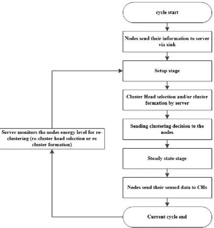
The clustering has a significant task on network lifetime because sensor nodes consume a considerable amount of energy during the transmission and receiving in order to perform the clustering function stages. Clustering is the process of grouping sensor nodes into groups that are administered by a node known as a cluster head (CH). The main stages of this function are the setup stage, responsible for the cluster formation and cluster head selection, and the steady state stage (data transmission). By managing and reducing the number and amounts of communications as well as computation during these stages efficiently, will affect the nodes’ energy consumption and enhance network lifetime.
The aim of this thesis is to improve the network lifetime by virtualising the clustering function to be implemented into high-volume central server on the cloud as well as using efficient approaches in cluster formation (based on k-means algorithm) and in cluster head selection (based on current nodes energy level and their distance to sink). These processes will result in a reduction in the number and amount of communication messages and the computational needs for each node during clusters formation and cluster head selection, thus improving the network’s lifetime. Hence, a new virtualised clustering routing protocol based on Network Function Virtualisation (NFV) has been proposed. NFV is a new network virtualisation approach that helps to minimise the design requirements in terms of hardware, power and space. The new approach uses a mathematical model which has been developed in this work to estimate the energy consumed during the operation of the proposed protocol.
2
Chapter One
Introduction
1.1 Introduction
Following the developments in the fields of Micro-Electro-Mechanical Systems (MEMS) technology and wireless networks, tiny sensor nodes with limited power and computing resources have been designed for the monitoring and controlling of physical environments (Akyildiz, Su, Sankarasubramaniam, & Cayirci, 2002a) (Potdar, Sharif, & Chang, 2009).
Wireless Sensor Networks (WSN) are a special kind of ad-hoc networks that gained considerable attention for its uses in various applications such as health and environment monitoring. This network composed of a large number of tiny, low cost and limited battery-powered sensor nodes collaborate with each other to perform various tasks. Therefore, because of the limited nodes’ energy resources, maximising network lifetime is one of the critical challenges that should be considered during the network design. Sensor nodes exhaust their power in various activities such as sensing, processing and communication that represents the most energy-consuming and therefore should be managed to improve the network lifetime.(Akyildiz et al., 2002a) (Alkhatib & Baicher, 2012) (Lewis, Moncrief-O’Donnell, & Chair, 2006).
3
WSN, they are used in different applications such as military, business, environmental, health, traffic monitoring and home monitoring (Tan, 2006) (Malfa, 2010).
The characteristics of WSN are different from other wireless networks because they are application-dependant. Many requirements should be considered when designing WSN; such as energy consumption, localisation, topology control, deployment, computation process, data aggregation, scalability, cost, hardware limitation and security (Tan, 2006) (Malfa, 2010).
One of the most important issues in the design of this network is how to prolong the network lifetime. The network lifetime is based on the energy level of the nodes which consume their energy in different activities, such as communication, sensing, data processing, and collision, (Patil & Patil, 2013).
Routing poses difficult challenges in the design of a sensor network because of its characteristics that distinguish it from other types of wireless network such as Mobile ad hoc Network (MANET) (Cecílio, Anjos, Costa, & Furtado) (Mundada, 2012). With regards to energy consumption, the routing process consumes a considerable amount of energy in the communication between sensor nodes to perform different functions such as clustering.
4
In this chapter, the research problems, question, aim, objectives and the strategy are defined. This is preceded by a brief description of Network Function Virtualisation (NFV) as it is an important component of the research
1-2 Network Function Virtualisation (NFV)
The European Telecommunications Standards Institute (ETSI) industry group has founded NFV to reduce network complexity. The NFV is one of the cloud computing applications. Cloud computing and NFV have some similarities but are essentially different. The network function virtualisation technique opened the field towards unifying the networks and information technologies by hosting the network functions in the cloud (corporation, 2013). This technique could apply to any network function and can reduce space, energy, cost and dependency of hardware components (Wikibon, 2013).
The notion of this virtualisation technique came from the need of the network providers to accelerate the deployment of any new network services to support their growth objectives; this should reduce complexity and make network management faster and easier. The function virtualisation technique opened the field towards unifying the networks and information technologies (corporation, 2013; Taylor, CTO, & Networks, 2014). A simple concept of this technique is shown in Figure (1-1) (Wikibon, 2013) (ETSI, 2012) (Central, 2013; Pate, 2013).
5
Figure (1-1) NFV Concept ( http://slideplayer.com/slide/4680105/)
This technology has various advantages which can be summarised as follows: (ETSI, 2013b) (Radcom, 2013):
1. Reduces the dependency on specific hardware as well as minimising the purchase cost for new equipment. For instance, instead of adding new hardware to enable network encryption, software related to this function can be used.
2. Minimise the space and energy consumption for the network components. 3. Facilitation of the networks upgrade.
4. Allows network operators to share their resources with different services and customers.
1-3 Research Problem
6
the network lifetime. According to this, the improvement of the network lifetime is achieved by the reduction of the sensor nodes' energy consumption.
The nodes’ energy is consumed in different fields such as communication between the sensor nodes and the sink, sensing the environment, and processing the data. However, the most energy-consuming aspect is the communication. For example, the power to process thousands (approximately 3000) of instructions is equal to the power required to transmit a data of 1-bit size (Pottie & Kaiser, 2000) (Patil & Patil, 2013) (Ahmedy, Ngadi, Omar, & Chaudhry, 2011) (Ali & Roy, 2008) (Anastasi, Francesco, Conti, & Passarella, 2006).
In wireless sensor network (WSN), many functions affect the sensor nodes’ power level; the most important function is the routing. Hence managing the routing function will lead to reducing the energy consumption (Alkhatib & Baicher, 2012) (Ayyat, 2013) (Dekivadiya & Vadharia, 2012).
In general, routing is the process of transmitting the data from the source to the destination via the most efficient route; the routing has a significant and costly task in term of determining network lifetime in WSN.
The energy consumed in the routing process has been considered the highest due to various routing functions such as clustering, which relies on both Intra-communication (among sensor nodes) and inter communication (between sensor nodes and the sink). Therefore, the principal reduction of the energy consumption is achieved by minimising the Intra and inter communications (Akkaya & Younis, 2003).
7
formation and cluster head selection. In the setup stage, the sensor nodes consume a considerable amount of energy because of a large number of communication messages tramnsnitted during the clustering function (cluster formation and cluster head selection stages). In clustering sensor networks, routing protocols can be classified based on the responsibilities of the clustering function into distributed (the nodes responsible for the clustering function) and centralised entral node, generally the sink is in charge of this function. The distributed clustering is location unaware, which may lead to a non-uniform distribution of cluster head selection and cluster formation. Moreover, the clustering function occurs internally among the nodes, and this leads to an increase in the number of communications among the nodes to perform this role.
However, centralised clustering protocols are location aware, and there is a controller node (generally by the base station/sink), which controls and manages the cluster head selection, clustering formation and the number of clusters in the network. The initialisation of this type happens when the nodes send their information to the sink. Although it is better to be centralised than distributed, but the transmitting process that occur at the beginning of each round in the centralised type will cause extra energy consumption and overheads at the start of each round.
8
1-4 Research Question
As mentioned previously, Network Function Virtualisation is a new approach for virtualisation to reduce the complexity and operations of the networking system by moving the network function to be implemented in a central server.
Therefore, by using the principles of this new technique in WSN, the main question of the research is to move the cluster formation and cluster head selection to a central server in the cloud and enable this server to manage and control the network topology. This will help to enhance the network lifetime and organising the network to be more efficient in terms of energy. To verify this hypothesis, a new virtulised and central clustering based routing (VCR) protocol has been proposed.
1-5 Research Aim and Objectives
The aim of this research is to enhance the network lifetime in cluster based sensor networks by managing and controlling the clustering function by a central server. This will reduce the energy consumption that occurs during this function and enhance network lifetime as well as organise the network to be more efficient regarding energy consumption in addition to making the clustering function share with other networks
The key objectives, which are designed to achieve the aim of the research, are:
9
2- Design a virtualised and centralised clustering routing (VCR) protocol based on NFV to control a network topology and implement the clustering function.
3- Develop mathematical models for measuring the amount of energy consumption for the proposed protocol.
4- Simulate the proposed protocol and analyse the results to find the improvement of the network lifetime based on the first node dead (FND) parameter as a performance measure.
1-6 Contributions of the Thesis
To overcome the reseasrch problem, this thesis intends to utilise the concept of Network Function Virtualisation and smart environment of the cloud computing in designing a central clustering routing protocol to control and manage the clustering function in the network as well as use efficient approaches in cluster head selection and cluster formation in order to achieve the research aim. Therefore, the main contributions for the proposed protocol are:
1- Using a central control on the network will reduce the number and amount of communications that requires during the clustering function in distributed protocols. 2- Minimise the transmissions of nodes’ information, which occurs at the beginning of
each cycle in centralised protocols, by using one transmission process at the initialisation step of the protocol.
3- The server will utilise the nodes’ information to optimise the cluster head selection and cluster formation based on node’s current energy level and distance to balance the power consumption and improve network lifetime.
10
current energy level of the cluster head node and cluster members. This process will make cluster head reselection more monitoring more efficient.
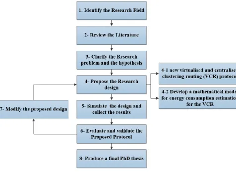
1-7 Research Process
The steps of the research process have vital importance in identifying the research field, selecting the main problem, proposing and implementing the design as well as evaluating and validating the results. The main steps of the research process are as shown in Figure (1-2). This section provides full information on the process of this thesis.
[image:27.595.90.567.323.685.2]11
1- Identify the Research Field
The first step of the process is to define the general field of this research. The research begins by carrying out a detailed analysis of the energy consumption problem in WSN, and the domains in which the sensor nodes consume energy, as well as which of these domains consume most energy, and how it should be modified to prolong the network lifetime
2- Review the Literature
This step provides the fundemantal knowledge about the research field. Much research has been reviewed to understand WSN functions, problems and applications, as well as different types of existing routing protocols, clustering protocols and algorithms had been reviewed in order to understand their fundamentals.
Furthermore, various mathematical models introduced for WSN were studied and reviewed to understand which domains should be taken into accounts during the design of the proposed mathematical model.
In addition to this, the NFV technique is a new network virtualised method to reduce the network complexity and power consumption. By taking all this into consideration, the main concept of this research study will be to exploit the NFV concept to minimise the energy consumption of the sensor nodes and improve network lifetime.
3- Clarify the Research Problem and the Question
12
reviewed in order to understand how the nodes consumes their power during the operation of the clsutering protocols and how it can be managed in order to improve the network lifetime.
4- Propose the Research Design
Based on the research problem and hypothesis, a research design has been proposed in order to achieve the aim and objectives. It is divided into two phases:
4-1 Propose a New Virtualised and Centralised Clustering based Routing Protocol
for the Research Idea.
In this phase, a new virtualised and centralised clustering protocol is proposed. In the proposed protocol, the NFV server will be responsible for implementing the clustering function. Its operation based on two main steps: the neighbour discovery step, which will be used to send the sensor nodes’ information to the server via the sink; and the clustering step, which will be implemented in the NFV server. The clustering step will be divided into the setup stage (the cluster formation and the cluster head selection) and steady state stage (data transmissions). Besides this, the k-means clustering algorithm is used to form the final clusters. The selection of the cluster head is based on a particular cost function, which is the combination of nodes distance to sink and its current energy level. The full details of the proposed protocol are discussed in chapter four.
4-2 Develop a Mathematical Model to Estimate the Amount of Energy Consumption
for the Nodes
13
The model takes into consideration the fields that nodes consume their energy in, such as transmission, receiving, processing, sensing and status change.
5- Simulation of the Proposed Protocol.
This research is based on a simulation experimental and will therefore study and investigate the amount of energy consumption of the new protocol under different simulation parameters. In this step, the protocol is implemented and managed using the MATLAB R2016a simulator.
At the beginning of the simulation, the networks are fed with the necessary information such as the number of nodes, which are deployed randomly in the simulation environment (the sensing area with m*m size), the sink (base station) position. As soon as the nodes are deployed, they will be in stationary mode (fixed position).
The simulation is run under different topologies (randomly deployed) to investigate the network energy consumption. In addition to that, the number of nodes, the sink position and the sensing area are used as inputs. These are changed during the simulation to study their effects on the network and to find the best scenario for the network working in terms of minimum energy consumption.
14
6- Evaluate and Validate the Proposed Protocol
The results obtained from the simulation for the proposed protocol is collected and analysed in this step. Additionally, the protocol is validated based on different scenarios such as changed numbers of clusters and modified implementation parameters
The purpose of the proposed protocol evaluation to determine how far it achieves the aim of the research; this is done by comparing it with the traditional protocol (LEACH) and LEACH-C to find the difference between the results.
7- Modification to Improve the System.
During the simulation process, and if the amendment is necessary to improve the performance of the proposed protocol to minimise the energy consumption, this step is used to modify the protocol according to the evaluation of the results.
8- Produce a Final PhD Thesis.
The final step will involve making conclusions and recommendations, then present the complete PhD thesis.
1-7 Thesis Layout
The remainder of the thesis is organised as follows:
15
- The detailed information about the clustering technique is been explained in Chapter 3. Furthermore, the main classification for the available clustering protocol, which is distributed, and centralised clustering protocols had been introduced and various types of available protocols in both types has been described.
- The full description, assumptions and general steps for the proposed protocol are present in Chapter 4.
- The mathematical model and the final equations that will be used to measure the amount of energy consumption in the proposed protocol will be reviewed in chapter 5.
16
Chapter Two
An Overview of Wireless Sensor Networks
2-1 Wireless Sensor Networks Background
Wireless Sensor Network (WSN) represents a class of network technology that is becoming increasingly popular today. WSNs are used to control and monitor the environment, and they contain thousands of sensors that communicate with each other to perform a particular task. Sensing is a technique that is used to collect information about a particular phenomenon or environment (Dargie & Poellabauer, 2010).
A sensor node forms the main unit of a WSN, which is used to measure changes in the environment such as vibration, temperature, pressure, humidity, noise and pollution. These sensor nodes are deployed randomly and in large density (Akyildiz et al., 2002a; Kalantary & Taghipour, 2014; Potdar et al., 2009).
The functions of these sensor nodes are transmitting the data, processing it and then communicating with each other to forward it to a central node, which is known as a base station or a sink via shared wireless channels. The sink either uses the data locally (sends it to users) or forwards it to other networks (such as the Internet) (Akyildiz et al., 2002a).
The main components of standard Wireless Sensor Network (WSN) are shown in Figure (2.1) and consist of:
1- Sensing area that can be considered as the field where the nodes will be deployed. 2- Sensor nodes, which represent the main part of the network and the heart of it and are
17
3- Sink or Base Station, which is the node responsible for control of the network and its high proprieties node with no limited resources. The sink acts as a gateway between the sensor nodes and the outer world. The sink needs to be in a good position because all the nodes communicate with it for network operation, and in general, the sink is assumed to be static and does not move in most of the available applications, except for some applications where the sink needs to move to collect data from the nodes.
Figure (2-1) Simple Diagram of a WSN
18
Although this network is a type of ad hoc network, there are various reasons why the protocols designed for ad hoc cannot be used in the WSN. For instance, the number of sensor nodes in the WSN is huge, and this requires more scalability management. The sensor nodes are deployed once and in stationary mode, except for some applications that require mobility nodes. In ad hoc, however, the nodes are moving all the time. Moreover, the sensor nodes in the WSN have limited capabilities, such as in processing and energy constraints, and are also prone to failure. The overhead of the communication for network configuration is also too high, and in the WSN, the nodes use broadcasting during the operation while in the other ad-hoc network such as MANET, the nodes use the peer to peer communication. As a result, minimising energy consumption is the most significant problem in the design of the WSN (Gowrishankar, Basavaraju, Manjaiah, & Sarkar, 2008).
The design of WSN has special requirements such as power limitations, processing abilities, memory, fault tolerance, scalability, hardware constraints, transmission media, environment, deployment process, Quality of Service (QoS) and security (Akyildiz et al., 2002a; Potdar et al., 2009; Singh & Arora, 2013; Yick, Mukherjee, Ghosal, & Dipak, 2008).
2.2 Wireless Sensor Networks Characteristics
WSNcharacteristics are different from other types of wireless networks because it is an application dependent and changeable based on the network design; some of its features are (Akyildiz, Su, Sankarasubramaniam, & Cayirci, 2002b; Potdar et al., 2009; Singh & Arora, 2013; Yick et al., 2008):
19
nodes are battery powered, and the nodes are deployed in an unreachable environment, it is thus hard to replace the nodes’ batteries or charge them with additional energy. 2. Limited resources: owing to the sensor nodes’ small size and battery power, the
processing ability is limited, as well as memory storage and lifetime.
3. Deployment: the deployment of sensor nodes in the network is application dependent and random. It has two types predetermine and post determine. In the predetermined type, the nodes deploy either dropping from a plane or are placed in the sensing field one by one by a human or robot. For the post deployment, there is a change in the topology by changing nodes’ position and their abilities.
4. Fault tolerance and topology control: the fault of the sensor network should not affect the performance of the WSN function and should have the ability to change the topology map in case of any failure. This failure may be caused by various factors such as lack of power, physical damage and environment interference.
5. Application dependent: the characteristics are different from one application to another, so the protocols and algorithms for it are application specific.
6. Scalability: depending on application requirements, the number of sensor nodes may be increased or decreased. Therefore WSN performance should be continuous if new sensor nodes are added or removed.
7. Security: security is considered a major factor in WSN design to ensure application processing. Confidentiality, availability, integrity, authentication, authorization and others represent various security parameters. For instance, if the WSN is used in the military application, it requires a high level of authentication.
20
applications. This type is considered to be the most energy-saving, as the nodes turn the radio to on only on their time slot. Event based types are commonly used in critical applications. The nodes operation here depends on a specific event to start working. For those applications that require data, when the nodes send their information based on a request from the sink, this type is known as query based data reporting. The data reporting this model has a higher priority than the previous two models. Finally, the combination of the three models is called the hybrid model.
9. Mobility: the nodes in this network may or may not have mobility properties. In general, most of the available designs of this network consider the nodes to have a fixed position. However, some applications require the nodes to be mobile and change their position based on specific conditions.
10.Production Cost: the main part of the WSN is the sensor node. Therefore, the cost of the single nodes has a significant impact on the design cost of the whole network.
To understand the fundamentals, architecture, design issues, connectivity schemes and problems of this type of network. Akyildiz et al. (2002a) introduced full studies and surveys in this field, providing the necessary background required for understanding this network type and its limitations. Furthermore, in order to understand the WSN architecture, a brief background on WSN architecture based in OSI model was introduced in (Alkhatib & Baicher, 2012).
In order to summarise the design limitaition and chalalnges in WSN, (Singh & Aloney, 2015) focusing on the general limitations and challenges of WSN that provide the necessary information regarding to the design of this network.
21
various techniques of node localisation discovery were raised by Pal (2010) who discussed the future directions and challenges to improve localisation techniques in WSN.
2-3 Sensor Nodes Architecture
Sensor nodes are considered to be the main part of WSN, and they are used for sensing, processing and sending the data to the central nodes (sink). There are different types of sensor nodes such as thermal, seismic, infrared and acoustic that are used to sense different environment conditions such as vibration, temperature, pressure, noise, humidity, pollution, radiation, and the characteristics of the objects such as speed and the direction (Hu & Cao, 2010).
The sensor nodes contain various components as shown in Figure (2-2) and described in the following:
1- Sensing unit: this unit consists of sensors and analogue to digital converters. The sensor can be analogue or digital, and it is used to sense the environment and convert the data using ADC into a signal to be usable in the network.
2- Processing and storage units: the processor contains a microprocessor that is used to control and execute the protocols and algorithms; for the storage unit, it can be used to store the sensing data, and it is optional and depends on nodes’ model and characteristics.
3- Transceiver units: in this unit, the radio system is used in the communication mode with neighbours.
22
Based on the application type, some sensor nodes contain location units that define their position. In some conditions, it is necessary for the nodes to know their position; for instance, in tracking or event-based applications, the nodes should provide the location of the events with the sensing information.
Additionally, a mobilised unit enables the sensor nodes to move in the sensing area based on the sensing task that they perform.
Figure (2-2) Sensor Node’s Architecture
2-4 Wireless Sensor Network Applications
23
WSNs have the ability to perform many applications that help people to examine and understand the sensed environment easily. The application can be classified according to the reporting type, such as event-based, query based and time-driven based.
There are various types of sensor network applications, and they depend on application requirements such as deployment method, mode of sensing, type of power supply and others (Zhao & Guibas, 2004).
WSN applications are categorised into tracking applications and monitoring applications. Various types of WSN applications are shown in Figure (2-3). This section will briefly introduce different types of these applications.
1- Military Applications: WSN has an important role in the military field. This network can be used for tracking and monitoring military forces and enemy forces, equipment and battle areas (Akyildiz et al., 2002a).
2- Health and Medical Applications: WSNs can be utilised in the health field to monitor patients, such as their blood pressure and heart rate and tracking their movement without the need to stay at the hospital. In addition to this, it can be used to track the doctors’ movements (Abidi, Jilbab, & Haziti, 2017) (Dargie & Poellabauer, 2010).
3- Environment Applications: this application represents the first application that was implemented by WSN, as it was used to monitor the environment situation such as seismic system, flood detection, pollution, climate, temperature, humidity, light and pressure as well as monitoring environmental resources such as soil and water quality. In addition to that, it is used in animal tracking and monitors behaviour. WSNs have been widely applied in this type of application (Rajaravivarma, Yang, & Yang, 2003). 4- Home applications: sensor nodes can be used to help people monitor and manage their
24
5- Transportation Applications: this system is used to track and control the traffic flow, car speed, congestion control and other traffic conditions (Dargie & Poellabauer, 2010). 6- Building Applications: recently, sensor networks have been used in structure
applications to monitor the building, bridge or a motorway condition and quality. For instance, it is used to monitor the stress, temperature and any cracks occurring in the structure (Buratti, Conti, Dardari, & Verdone, 2009) (Pakzad, Fenves, Kim, & Culler, 2008).
Figure (2-3) WSN Applications
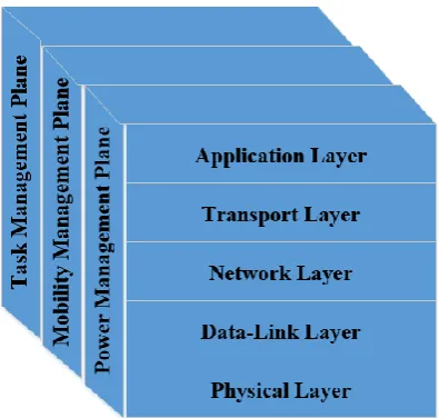
2-5 Wireless Sensor Network Protocol Stack
25
Figure (2-4) WSN Protocol Stack
Basically, in the WSN, the protocol stack consists of five layers, which are: the physical layer, data link layer, network layer, transport layer, and the application layer. Additionally, there are three cross layers, which are power management plane, mobility management plan and task management plane. These added layers are managed, control the network and improve the nodes’ cooperation with each other and thus, will improve the network performance(G. Sharma, 2009) (Alkhatib & Baicher, 2012).
The physical layer is responsible for frequency selection, modulation, and demodulation, and receives and transfers the signals. It provides an interface for bits transfer over a physical medium. For the data link layer, it has a Media Access Control (MAC) that is used to minimise the collision among the nodes, error control, connection reliability as well as data stream multiplexing.
[image:42.595.217.415.69.257.2]26
For transport layer, the primary role is to provide reliability to control and minimise the data flow in the network based on the application requirements, to provide end to end reliability and security.
The last layer on the top is the application layer, which has the responsibility of representing the required data used software to the users, such as sensor network management. WSN is used in different applications in various fields such as military, medical and environment.
However, the crossover layers have different management functions. The power plane layer is to manage and controls sensor nodes’ power usage. In addition, it manage how the nodes can monitor their energy consumption during the performance of different operations such as sensing and communications. In the contrast, the mobility plan layer manages the mobility and movement of the nodes. Also, the sensing and data sending process are controlled and scheduled by the task plane layer (Mir, 2014; Sharma, 2009) (Al-Obaisat & Braun, 2007). Now, in order to understand the routing function, the next section contains the necessary information about what routing means, the routing protocols classifications, and the available routing protocols and algorithms.
2-6 Routing Protocols in WSN
27
The functions of the routing process in sensor nodes include establishing a connection with adjacent nodes to exchange information, building a routing table and sharing it with other nodes and calculating the best route. The implementation of these functions is achieved using routing protocols and algorithms (Al-Karaki & Kamal, 2005).
(a) Single Hop (b) Multi-Hop
Figure (2-5) WSN Communications type
The routing protocols and algorithms are sets of rules that manage the connection between two nodes, control the data transmission from one sensor node to another and calculate the best path to forward data from source to destination depending on certain metrics.
28
(Akkaya & Younis, 2003) (Al-Karaki & Kamal, 2004). According to these characteristics, various types of routing protocols and algorithms have been designed and proposed to implement data routing in WSN.
In WSN design, the routing protocol has been a focus in the research field. Routing protocols and algorithms are application-dependent, and their requirements differ from one application to another; for instance, protocols’ characteristics for environment monitoring applications are distinct from that needed for military use (Akkaya & Younis, 2003) (Eslaminejad & Razak, 2012) (Villalba, Orozco, Cabrera, & Abbas, 2009).
The routing communication method in WSN can be classified into the sink to nodes and nodes to sink. It depends on the type of protocol used in the network. For the first category, the sink is responsible for starting the communication process. It is subdivided into the sink to all, sink to one and sink to the group (Chen, Li, Ye, & Wu, 2007). For the nodes to sink, they are used in the data-centric system or networking system. This type has more overhead on node storage, energy and packet control than other types.
2-6-1 Design Requirements for WSN Routing Protocols
As mentioned previously, the sensor nodes have limited battery and processing, and therefore, to design routing protocols and algorithms in WSN, the following requirements should be considered (Al-Karaki & Kamal, 2004; Khurana, 2013; Sharma, 2009):
29
2- Node deployment: this is application dependent. The node deployment may be deterministic (sensor nodes are manually deployed, and their paths are predetermined) or randomise (sensor nodes deployed randomly).
3- Data reporting models: in WSN, sensed data sending from the sensor nodes can be categorised into continuous, event-based, query based and hybrid. In the continuous model, the sensor nodes send their data to the sink periodically at a particular defined rate. In the event-based model, the sensed data sending depends on the event detected. For query event-based, the sensor nodes send their data only when they receive a query from the sink. Finally, the hybrid model is a mix of the three mentioned models.
4- Fault tolerance: the network should not be affected by any sensor node failure, and that which is achieved by routing protocols should find alternative solutions.
5- Scalability: routing protocols and algorithms should have the ability to manage and control any change in the numbers of sensor nodes; this change may happen by adding or removing sensor nodes to/from the network.
6- Network dynamics: it is application dependent. Sensor nodes and the base station may be in either stationary mode (fixed position) or mobility mode (dynamic position).
7- Connectivity and coverage: this depends on the deployment of the sensor nodes.
8- Data aggregation: this means data collection from different resources and sends it as one packet in order to achieve energy efficiency.
30
10- Topology change: the network topology may change because of many reasons, such as node damage and link failure.
11- Node homogeneity/heterogeneity: this is application dependent. Homogeneity sensor nodes mean that all nodes have equal rules in computation, energy consumption and communication. Moreever, heterogeneity refers to the differences in sensor nodes’ rules.
12- Applications dependent: the design of routing protocols is application specific, which means that the routing characteristics are based on the network design requirement (Singh & Sharma, 2015).
2-6-2 CLASSIFICATION OF ROUTING PROTOCOLS IN WSN
The routing protocols in this network can be classified according to different parameters such as node location, node functionalities and other parameters; this section will illustrate a review of these classifications and their types. Figure (2-6) summarises the classification of routing protocols and algorithms.
31
2-6-2-1 Network structure-based Routing Protocols
The network structure category divided into flat, hierarchy and location based routing protocols ( Singh, Singh, & Singh, 2010) (Cecílio et al.) (Al-Karaki & Kamal, 2004, 2005), as follows:
I. Flat Routing Routing Protocols
All sensor nodes have the same functionality in flat routing protocl, as well as the communication, depend on sink query. The sink sends a query to a particular region and waits for a response from it. As it is query based, attribute-based naming is using for the data requested. There are different protocols, and algorithm examples include flooding, gossiping, Sensor Protocol for Information via Negotiation (SPIN), and Direct Diffusion.
II. Hierarchical and Clustering Routing Protocols
The main goal of Hierarchical and clustering is to reduce energy consumption by dividing the sensor nodes into clusters, and for each one there is a cluster head, which is responsible for managing and controlling all sensor nodes within it. Examples of this type are LEACH, Power-Efficient Gathering Algorithm in Sensor Information System (PEGASIS), Threshold-Sensitive Energy-Efficient Protocol (TEEN) and Adaptive Periodic TEEN (APTEEN). Full details of these categories are described in the next chapter.
III. Location-based Routing Protocols
32
also considered to be an energy saver because it allows the nodes to switch to sleep mode if there is no activity with it. Geographic Adaptive Fidelity (GAF), Energy Aware Greedy Routing (EAGR), and Geographical and Energy-Aware Routing Protocol (GEAR) are examples of this type.
2-6-2-2 Protocol Operation based Routing Protocols
Routing protocol in WSN has another important category that is based on the network operation. In this category, the protocols are performed based on the network requirement or what the network needs to operate based on a particular change. The operation-basedcategory is organised into:
I. Query-based Routing Protocols:
The operation of the protocols based on a query where the sink or destination node broadcasts a data request to all nodes in the networks. The sensor node will check if the query matches their sensed data or not, and if there is a match, the nodes send the required data to the sink or the requested nodes. Direct Diffusion and Rumour Routing are classified under this type.
II. Multipath-based Routing Protocols:
In the Multipath-based category, the protocol uses multipath to the sink to achieve high performance. The sensor nodes establish multipath from the source to destination, and this will increase the network reliability and performance and enhance its lifetime. Furthermore, the node can use the other paths to distribute their traffic between them. The best examples of this type are Directed Diffusion and Energy-Aware Routing Protocol.
III. Negotiation-based Routing Protocols:
33
data. After completing the negotiation process and establishing a connection to the required node, the actual data will be sent. The general example of this type is SPIN.
IV. QoS based Routing Protocols:
The protocol should have the ability to balance between data QoS requirements such as delay, sample rate, data accuracy, sufficient bandwidth and energy. The protocols in this type enable the nodes to make a trade-off between the energy consumption metric and various QoS metrics. Examples of this kind are SPEED (Stateless Protocol for Real-Time Communication in Sensor Networks) and SAR (Sequential Assignment Routing).
V. Non-Coherent and Coherent Based Routing Protocols
In non-coherent based routing, the data will be processed in the node before sending it to the aggregator for further processing. Data processing is achieved in three stages; the first stage includes target discovery, data gathering and data pre-processing, while the second phase confirms the connections, and finally, in the third stage the central node will be selected. An example of this type is Single Winner Algorithm (SWE).
However, in incoherent based routing, the level of data processing in the node before sending to an aggregator is limited. The limited processing includes time stamping, duplicating suppression and other. This type is the best choice to use in the energy efficient routing. An example of coherent based routing is Multiple Winner Algorithm (MWE).
2-6-2-3 Routes Establishment
34
I. Proactive Routing Protocols:
In this type of protocol, the nodes build their routing table to find the route to the destination before needed. The delay in this kind is minimising because the path is ready to use, but at the same time, the bandwidth may increase because of the updated information in the routing table. It is suitable for real-time applications. Examples of this type are Wireless Routing Protocol (WRP) and The Topology Dissemination Based on Reverse-Path Forwarding Protocol (TBRPF).
II. Reactive Routing Protocols:
Demands under these protocols determine the routing tables. It does not need to update the information because the table is already up-to-date, but the delay will increase because the tables are not ready and it should be determined. Examples of this type are: Temporarily Ordered Routing Algorithm (TORA) and Energy-aware Temporarily Ordered Routing Algorithm.
III. Hybrid Routing Protocols:
The protocols in a hybrid are a combination of the properties of the proactive and reactive protocols. This combination occurs because of the communication process between the sensor nodes, which are located in the same area and are therefore near to each other. At the same time, the topology’s changes are significant if the nodes are close to each other and will not affect other parts of network Zone Routing Protocol (ZRP).
35
A study by Ramya, Saravanakumar, & Ravi (2016) provided a review of the importance of the energy efficiency routing protocol in the design of wireless sensor network and of enhancing its lifetime; they introduced the available routing protocols as a classification and reviewed the characteristics for each of them.
The available energy efficient routing protocols were studied and discussed in (Devi & Sethukkarasi, 2016). They classified these protocols into different classifications and compared them based on the main parameter that should be taken into account in any routing protocols design.
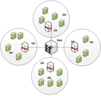
Among all classifications of routing protocols, the clustering based protocols are the most popular when considering sensor nodes’ energy saving. The idea of these protocols is based on dividing the network into clusters, which will be responsible for transferring data between sensor nodes and the sink. The communication with the sink is done via a head node, which is known as the cluster head. Various routing protocols can be classified as clustering-based protocols. Low-Energy Adaptive Clustering Hierarchy (LEACH) was the first protocol that used this technique, and Power-Efficient Gathering in Sensor Information Systems (PEGASIS), Threshold-Sensitive Energy-Efficient (TEEN) Protocol and Adaptive Periodic (APTEEN) are some further examples of this technique. The next chapter will review the basic principles of the clustering function.
2-7 Energy Consumption in Wireless Sensor Networks
36
designers should take into account energy consumption as the primary consideration in designing any algorithms or protocols (Singh & Arora, 2013).
The source of sensor nodes’ power consumption can be divided into useful consumption and wasteful consumption, as shown in Figure (2-7).
The useful consumption includes:
Communications (including both transmission and receiving): sensor nodes consume most of their power on communication, especially if nodes are located far away from the base station.
Sensing.
Data processing.
While the wasteful consumption domains are:
Collision: A collision occurs when some sensor nodes send data at the same time and on the same channel.
Overhead and overhearing: overhead means that sensor nodes exchange redundant data while overhearing occurs when a sensor node receives data that are addressed to other nodes.
Idle/sleep: if the sensor node is in idle mode (not receiving or transmitting any data), it will consume energy. Therefore, power management approaches are used to switch off the nodes when not in use.
Over-emitting: a sensor node consumes energy sending the data, and the destination is not ready.
37
Figure (2-7) Energy Consumption Domains
The highest amount of energy is consumed in the communication field. For example, and based on the research; the power consumption for processing approximately 3000 coded in the processor units is equal to the energy that is consumed to transmit 1 bit of data. Therefore, managing the communication field is necessary to improve the network lifetime (Pottie & Kaiser, 2000) (Ahmedy et al., 2011) (Ali & Roy, 2008) (Anastasi et al., 2006) (Rezaei & Mobininejad, 2012).
One of the primary issues in the design of WSN is the energy management and how its consumption can be minimised. Shaikh & Zeadally (2016) proposed a taxonomy of the available energy harvest sources that can be used in the design of WSN. In addition to that, the paper introduces a review of the available energy models used in energy harvest.
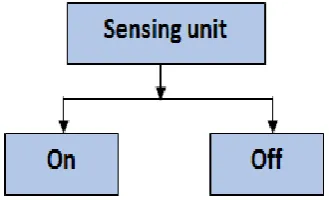
38
modes: active, sleep and idle. For each mode within the component, there is a certain amount of energy consumption depending on the design criteria and characteristics and sensor node models (Adinya & Daoliang, 2013) (Zhou, Luo, Gao, & Zuo, 2011).
The power exhaustion in a routing function is more than other functions because it is based on the communication between sensor nodes, computation process, packet size, sensor
Figure (2-9) Transceiver Component Modes Figure (2-8) Sensing Component Modes
[image:55.595.224.389.156.256.2]39
nodes status and the distance between sensor nodes and the sink. The aim of most researches has been to find schemes to increase network lifetimes. Some of these plans reduce the number of communications, by minimising the packet size, using efficient duty cycle mechanisms, optimising neighbour selection and reducing the distances that control the on and off status of sensor nodes.
A new energy conservation scheme was proposed by (Pantazis, Vergados, Vergados, & Douligeris, 2009) (Pantazis, Nikolidakis, & Vergados, 2013). This system was based on reducing the end-to-end delay. The researchers recommended using it with a network that monitors rare events and operates for a long time. In addition, (Anastasi, Conti, Di Francesco, & Passarella, 2009) introduced a classification of energy saving methods such as data based and duty cycling based.
The energy saving methods in WSN were presented by (Ali & Roy, 2008). The conservation methods have been classified according to node level, network level and software level. Packet size optimisation have also been used to enhance energy consumption in wireless sensor networks.
However, there are different surveys, which were introduced in this area, such as a study of power saving and energy optimisation techniques as presented in (Sendra, Lloret, García, & Toledo, 2011), where the authors presented the available methods used to reduce the energy consumption in WSN and increase network lifetime.
40
In routing, routing protocols and algorithms can use these schemes to achieve energy efficiency in networks (Thangadurai & Dhanasekaran, 2013), and energy harvesting has been the objective of much research in this field. (Anastasi et al., 2006) Discussed various approaches such as supplying energy from external sources or saving energy using efficient protocols and algorithms that can save sensor nodes’ battery life. A study of sensor nodes’ power management was carried out by (Ahmedy et al., 2011).
Energy gains significant attention during the design of new protocols and algorithms in the routing process. The communications among sensor nodes, the packet size, the distance between sensor nodes, the sink, and the sensor nodes' idle mode are the main sources of power dissipation in routing. There are various types of routing protocols whose primary design factor is reducing energy consumption, such as Low Energy Adaptive Clustering Hierarchy (LEACH), Sensor Protocols for Information via Negotiation (SPIN) and Energy-aware routing protocol (Cecílio et al.).
2-7-1 Sensor Node and Network Lifetime
The sensor node’s energy level had a significant effect on the Network lifetime, which is an important performance metric in Wireless Sensor Networks (WSNs).
There are three principal ways to determine the network lifetimes (Tian & Georganas, 2002) (Madan & Lall, 2006):
1- The time duration between the start of communication and the time when the first node dies (FND).
2- The time duration between the start of communication and the time when the half of the nodes die (HND).