ENHANCING THE BIT ERROR RATE PERFORMANCE OF
ULTRA WIDEBAND SYSTEMS USING TIME-HOPPING
PULSE POSITION MODULATION IN MULTIPLE ACCESS
ENVIRONMENTS
HASAN HATEM HASAN MOSA
ENHANCING THE BIT ERROR RATE PERFORMANCE OF
ULTRA WIDEBAND SYSTEMS USING TIME-HOPPING
PULSE POSITION MODULATION IN MULTIPLE ACCESS
ENVIRONMENTS
HASAN HATEM HASAN MOSA
School of Computing, Science and Engineering
College of Science and Technology
The University of Salford, Salford, UK
i
TABLE OF CONTENTS
TABLE OF CONTENTS ... i
LIST OF ABBREVIATIONS ... v
LIST OF SYMBOLS ... ix
LIST OF FIGURES ... xiii
LIST OF TABLES ... xviii
ACKNOWLEDGEMENTS ... xix
DEDICATION ... xx
ABSTRACT ... xxi
CHAPTER 1 ... 1
1 INTRODUCTION ... 1
1.1 Overview ... 1
1.2 The Main Research Question ... 3
1.3 Research Aim and Objectives ... 3
1.4 Contribution of Knowledge ... 7
1.5 Research Methodology ... 7
1.6 Thesis Structure ... 10
CHAPTER 2 ... 11
2 Background and Literature Review ... 11
ii
2.2 UWB Early Motivation and History ... 11
2.3 UWB Standards ... 14
2.3.1 Standards Definition ... 14
2.3.2 Defining a UWB Standard ... 15
2.3.3 UWB IEEE 802.15.3a Standard ... 16
2.4 Why Ultra-Wideband Impulse Radio?... 17
2.5 UWB Technology ... 28
2.6 UWB Signal Definition ... 32
2.7 UWB Waveform Generation (A Train of Gaussian Monocycles) ... 34
2.8 UWB Multipath Channel Model ... 43
2.8.1 Multi-path Fading ... 44
2.8.2 Types of Fading Effects ... 45
2.8.2.1 Small-scale Fading ... 46
2.8.2.2 Large-scale Fading ... 47
2.8.2.3 Lognormal Shadowing ... 49
2.8.3 Statistical Representation of fading Channels ... 49
2.8.3.1 Rayleigh Distribution ... 49
2.8.3.2 Rician Distribution ... 50
2.8.3.3 Nakagami m-Distribution ... 50
2.8.3.4 Lognormal Distribution ... 50
iii
2.8.5 UWB Channel Models ... 51
CHAPTER 3 ... 53
3 UWB MODULATION TECHNIQUES AND UWB WAVEFORM ... 53
3.1 UWB Waveform - Symbol Representation in Time Domain ... 53
3.2 Time Hopping Spread Spectrum (THSS) ... 55
3.2.1 The Modulation Schemes in Time-Hopping Format ... 60
3.3 UWB Modulation Schemes ... 61
3.3.1 Pulse Position Modulation (PPM) ... 62
3.3.1.1 Type-A TH-PPM UWB System ... 63
3.3.1.2 Type-B TH-PPM UWB System ... 66
3.3.2 Pulse Amplitude Modulation (PAM) ... 69
3.3.3 Binary Phase Shift Keying (BPSK) or Biphase Modulation ... 71
3.3.4 On-Off Keying (OOK) ... 73
CHAPTER 4 ... 75
4 THE MATHEMATICAL MODELS FOR A SYNCHRONOUS MULTIPLE ACCESS TH-PPM UWB SYSTEMS ... 75
4.1 Introduction ... 75
4.2 The TH-PPM UWB System Model ... 76
4.2.1 Pulse Train ... 77
4.2.2 Time Hopping Process ... 79
iv
4.3 Gaussian Pulse Model ... 80
4.4 The Receiving Process ... 84
4.5 The Gaussian Approximation (GA) Model ... 88
4.6 Exact Multi Access Interference Model ... 95
CHAPTER 5 ... 104
5 RESULTS AND DISCUSSION ... 104
5.1 Results of Gaussian Approximation ... 104
5.2 Results of Exact BER ... 114
5.3 Comparison Between the GA and the Exact Numerical Results ... 120
CHAPTER 6 ... 123
6 CONCLUSION AND FUTURE WORK ... 123
REFERENCES ... 127
v
LIST OF ABBREVIATIONS
ADSL Asymmetric Digital Subscriber LineANSI American National Standards Institute AWGN Additive White Gaussian Noise BER Bit Error Rate
BPSK Binary Phase Shift Keying cdf cumulative density function CF Characteristic Function
CW Carrier-Wave
DAB Digital Audio Broadcast
DC Direct Current
DS/SS Direct Sequence Spread Spectrum EIRP Effective Isotropic Radiated Power ETSI European Technical Standards Institute FCC Federal Communications Commission FDD Frequency Division Duplex
FFT Fast Fourier Transform
FH/SS Frequency-Hopping Spread Spectrum FWA Fixed Wireless Access
vi GPR Ground Penetration Radar GPS Global Positioning System
HF High-Frequency
IEEE Institute of Electrical and Electronic Engineers IF Intermediate Frequency
IRCC International Radio Consultative Committee ISDB Integrated Services Digital Broadcasting ISI Inter Symbol Interference
ISO International Standards Organisation ISM Industrial, Scientific and Medical ITU International Telecommunication Union I-UWB Impulse - Ultra Wide Band
LANs Local Area Networks LMS Land Mobile Satellite LOS Line-Of-Sight
vii MPCs Multi-Path components
NB Narrower Band
NLOS Non-Line-Of-Sight
NOCs Network & Optical Communication (research group) OFDM Orthogonal Frequency Division Multiplexing
OOK On-Off Keying
PAM Pulse Amplitude Modulation PANs Personal Area Networks
PCS Personal Communication Services pdf probability density function PDP Power-Delay Profiles
PN Pseudo-random Noise
PPM Pulse Position Modulation PRI Pulse Repetition Interval PSD Power spectral density PTM Pulse Time Modulation
RF Radio Frequency
RMS Root Mean Square
RS Rician shadowed
RV Random Variable
viii TDC Time Domain Corporation
TH Time Hopping
TH-PPM Time Hopping- Pulse Position Modulation THSS Time Hopping Spread Spectrum
TM-UWB Time Modulated- Ultra Wide Band UHF Ultra High Frequency
UMTS Universal Mobile Telecommunication System UWB Ultra-Wide Band
VHF Very High Frequency
ix
LIST OF SYMBOLS
Ak Attenuation associated to the kth transmitter.B Channel bandwidth.
bj Modulation date bit.
C Channel capacity.
cj
Pulse shift pattern represents a distinctive time-hopping sequence (Decimal PN code assigned for the jth monocycle).
) (k
j
c Decimal PN code assigned for the j
th monocycle for the kth user that
determines the time hopping sequence.
di(k) The ith binary data bit transmitted by the kthsource.
Eb Bit energy.
F Fourier transform.
fC The center frequency.
fH The upper frequency of the -10 dB emission point.
fL The lower frequency of the -10 dB emission point.
I The total MAI due to all Nu-1 interfering signals.
N Noise Power.
Nh The number of time slots per frame (number of chip "hops" per frame).
N0 Noise energy.
Ns Repetition code length (the number of pulses per bit).
x ntot(t) The overall interference and noise.
Pe Probability of error.
p(t) The UWB pulse shape. P0(t) The Gaussian pulse.
PG(t) Gaussian function.
PG0(t) Zero order Gaussian pulse in time domain.
PGn(t) n order Gaussian pulse in time domain.
Pn(t) The nth-order Gaussian monocycle.
Rb The bit rate.
R(x) Autocorrelation function. Rt(x) Cross correlation function.
) ( (0k,)j t
R The value of the cross correlation at the time when the first data bit of the k th
user is sent, for the jth pulse.
) ( 1(,kj) t
R The value of the cross correlation at the time when the second data bit of the kth user is sent, for the jth pulse.
r(t) The received signal.
S Signal power.
s(t) The transmitted signal.
S(k)(t) The transmitted signal of TH-IR system from the kthuser.
xi SNRout(Nu)
Average output signal-to-interference-plus-noise ratio of impulse radio for randomly selected time-hopping sequences as a function of the number of users.
Tb Bit duration.
Tc Time hopping chip width.
Tf Frame width.
Tp Impulse width (pulse length).
t(k) The kthtransmitter clock time. v(t) Template wave.
αj Single correlation process of each pulse.
βk Uniformly distributed over [0, Ns - 1].
γ Correlation receiver decision statistic. δ The time shift associated with PPM.
δopt
The optimum value of δ determined from the autocorrelation properties of the Gaussian pulses.
δD(.) The Dirac delta function which decides the clock timing of the pulses.
εn Energy normalisation factor assigned for the Gaussian pulses.
η The fractional bandwidth.
xii
2
rec
Variance of the receiver noise component at the pulse train integrator
output.
τk
Time delay shifts associated to propagation and synchronism between the number of users clocks of the transmitted signals.
τp
Time normalisation factor or (impulse width parameter) to make Pn(t)
independent of a specific impulse duration. )
(
,
) (k X
The characteristic function of X(k) condition on αkand βk.
) (
,
) (k Y
The characteristic function of Y(k) condition on αkand βk.
) ( ) (k I
The characteristic function of I(k) condition on αk.
) ( I
The characteristic function of the total interference.
) ( n
The characteristic function of the noise term n.
) (
The characteristic function of the total interference parameter.
xiii
LIST OF FIGURES
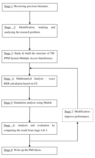
Figure 1-1 Research Methodology ... 9
Figure 2-1 The IEEE 802 organisation, [28]. ... 15
Figure 2-2 Division of the UWB spectrum from 3.1 to 10.6 GHz into band groups containing subbands of 528 MHz in MB-OFDM systems [34]. ... 17
Figure 2-3 Comparison of Short-Range Wireless Spatial Capacities... 20
Figure 2-4 Comparison between UWB and IEEE 802.11a in terms of throughput and the distance covered. ... 21
Figure 2-5 UWB Emission Limit for Indoor and Outdoor Systems [44]. ... 23
Figure 2-6 Power Spectral Density of an UWB Signal Compared to Noise Floor ... 24
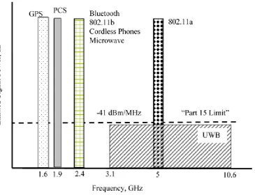
Figure 2-7 Frequency Occupation of UWB and Other Current Radio System ... 25
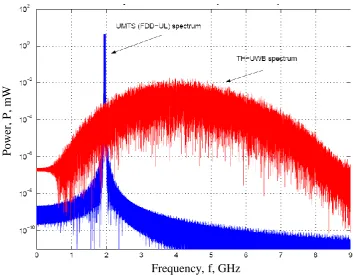
Figure 2-8 Spectra of fully loaded UMTS FDD uplink band and UWB signal using a Gaussian pulse waveform, [48] ... 27
Figure 2-9 Comparison of the Fractional Bandwidth η of a Narrowband (NB) and Ultra-Wideband (UWB) Spectrums ... 28
Figure 2-10 Comparison of impulse and multi-carrier UWB spectrums, [25] ... 30
Figure 2-11 UWB Signal Design Points, [28] ... 33
xiv
Figure 2-13 Different order Gaussian pulses in f-domain. ... 40
Figure 2-14 First order Gaussian pulse in t- and f-domains with different pulse widths. ... 42
Figure 2-15 Illustration of Multipath Propagation Environment... 45
Figure 2-16 Small-Scale vs. Large-Scale Fading. ... 45
Figure 2-17 Types of Small-Scale Fading. ... 46
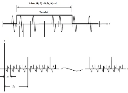
Figure 3-1 Symbol Representation of A Single Bit for UWB Waveform in Time Domain. ... 54
Figure 3-2 Block Diagram of the Spread Spectrum System. ... 55
Figure 3-3 Uniform pulse train in time and frequency domains. ... 56
Figure 3-4 Periodic and un-periodic pulse trains and their spectra. ... 57
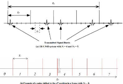
Figure 3-5 Typical Behaviour of a Time Hopping UWB Signal. ... 58
Figure 3-6 PPM Pulse Shapes for '1' and '0' Bits. ... 63
Figure 3-7 Uniformly Spaced Pulse Train with PPM dithering. ... 64
Figure 3-8 Example of Type-A TH-PPM Asynchronous Multiple Access Format. ... 65
Figure 3-9 Type-B PPM Transmission of Bit '0' and '1'. ... 66
Figure 3-10 TDC's Illustration of PPM Modulation Technique. ... 67
xv
Figure 3-12 Type-B TH-PPM UWB System. ... 69
Figure 3-13 PAM with Two Different Levels for Logical Bits '0' and '1', [52]. ... 69
Figure 3-14 Probability of error for M-ary PAM modulation, [28]. ... 70
Figure 3-15 BPSK Pulse Shapes for '1' and '0' Bits, [52]. ... 71
Figure 3-16 TH-BPSK in Time-Domain Using 2nd Order Gaussian Monocycles. ... 72
Figure 3-17 OOK Pulses Used for '1' and '0' Bits, [52]. ... 73
Figure 4-1 TH-PPM UWB System in Time Domain. ... 78
Figure 4-2 Second Order Gaussian Monocycle. ... 81
Figure 4-3 Autocorrelation of different order Gaussian monocycles. ... 82
Figure 4-4 Autocorrelation of Second Order Gaussian Monocycle. ... 82
Figure 4-5 TH-PPM Template Wave Form v(t). ... 84
Figure 4-6 The Simple Design of a UWB Correlation Receiver. ... 85
Figure 4-7 Receiver Block Diagram for the Reception of the First User's Signal, [19]. ... 87
Figure 4-8 Total number of users versus additional power required in (dB) for the impulse radio UWB. ... 92
Figure 4-9 P(δ) Function [110]. ... 94
xvi
Figure 5-1 Average BER of the TH-PPM UWB system versus SNR for a repetition code Ns= 1, in terms of variations in Tf, Rb. ... 105
Figure 5-2 Average BER of the TH-PPM UWB system versus SNR for different order Gaussian monocycles, in case of no MAI. ... 106
Figure 5-3 Average BER of the TH-PPM UWB system versus SNR for different values of time shift δ, in case of no MAI. ... 107
Figure 5-4 Average BER of the TH-PPM UWB system in indoor environments for small and high values of SNR, with a repetition code Ns= 2, and different small number of users. ... 109
Figure 5-5 Average BER of the TH-PPM UWB system in outdoor environments for small and high values of SNR, with a repetition code Ns= 2, and different large number of users. ... 110
Figure 5-6 Average BER of the TH-PPM UWB system versus SNR assuming number of users Nu = 48 for a repetition code with Ns= 2, Ns= 6, and Ns= 10. ... 111
Figure 5-7 Average BER of the TH-PPM UWB system versus SNR comparison between two cases Nu= 64 and Nu= 32 for a repetition code with Ns= 6, and Ns= 10. ... 112
Figure 5-8 Average BER of the TH-PPM UWB system versus SNR for Ns=8, assuming seven asynchronous interferers showing the effect of different pulse widths τp. ... 114
xvii
Figure 5-10 Average BER of the TH-PPM UWB system versus SNR for a repetition code with Ns = 6 showing the effect of different number of time hopping compartments Nh on the performance of the system. ... 116
Figure 5-11 Average BER of the TH-PPM UWB system versus SNR for a repetition code with Ns = 6 showing the effect of different number of users on the performance of the system operating the system in an indoor environment. ... 117
Figure 5-12 Average BER of the TH-PPM UWB system versus SNR for a repetition code with Ns = 2, Ns = 6, and Ns = 10 assuming seven asynchronous interferers... 118
Figure 5-13 Average BER of the TH-PPM UWB system versus SNR assuming seven asynchronous interferers, showing the effect of changing the bit rate for a repetition code with Ns = 2 and Ns = 8. ... 119
Figure 5-14 Comparison between the exact MAI and GA models, in terms of different accessing number of users in Nu, in evaluating the performance of TH-PPM UWB systems in an asynchronous multiple access environments. ... 120
xviii
LIST OF TABLES
Table 1-1 short-Range wireless Properties [8] ... 4
Table 2-1 Summary of the centre frequencies of the first five derivatives of the Gaussian pulse. ... 37
Table 2-2 Typical parameters of Gaussian waveforms for defined pulse lengths... 41
Table 2-3 Typical Path Loss Exponents for Outdoors Environments. ... 47
Table 2-4 Typical Path Loss Exponents for Indoor Environments [67]... 48
Table 3-1 TH Pattern and Bit Sequences used in the example of Figure 3-8... 64
xix
ACKNOWLEDGEMENTS
xx
DEDICATION
xxi
ABSTRACT
Ultra-Wide Band (UWB) technology is one of the possible solutions for future short-range indoor data communication with uniquely attractive features inviting major advances in wireless communications, networking, radar, imaging, and positioning systems.
A major challenge when designing UWB systems is choosing a suitable modulation technique. Data rate, transceiver complexity, and BER performance of the transmitted signal are all related to the employed modulation scheme. Several classical modulation schemes can be used to create UWB signals, some are more efficient than others. These schemes are namely, Pulse Position Modulation (PPM), Pulse Amplitude Modulation (PAM), Binary Phase Shift Keying (BPSK), and On-Off Keying (OOK) are reviewed. In the thesis, the performance of PPM system, combined with Time Hopping Spread Spectrum (THSS) multiple access technique is evaluated in an asynchronous multiple access free space environment. The multiple access interference is first assumed to be a zero mean Gaussian random process to simulate the scenario of a multi user environment. An exact BER calculation is then evaluated based on the characteristic function (CF) method, for Time Hopping-Pulse Position Modulation Ultra Wide Band (TH-PPM UWB) systems with multiple access interference (MAI) in AWGN environment. The resulting analytical expression is then used to assess the accuracy of the MAI Gaussian Approximation (GA) first assumed. The GA is shown to be inaccurate for predicting BERs for medium and large signal-to-noise ratio (SNR) values.
1
CHAPTER 1
1
INTRODUCTION
1.1
Overview
High data rate wireless communication has been one of the major drivers in the development of communications in last 20 years. The great popularity of cellular phones, radio paging, mobile computing devices and other Personal Communication Services (PCS) demonstrates the rising demand for high speed data communication [1]. Rapid growth in mobile computing and other wireless data services are stimulating many proposals for high-speed data services up to 2 Mb/s for diversified applications. In addition to mobile applications, Fixed Wireless Access (FWA) technologies bring high quality telephony, internet access, and multimedia service to the home over wireless links. Research challenges for high data rate wireless communications include the development of efficient coding and modulation schemes, smart signal processing techniques to improve the quality of service, enhanced spectral efficiency of the wireless system, and better techniques for sharing the limited spectrum among different high capacity users [1]. Remarkable technologies have been proposed to deal with these challenges, such as multiple antenna system, space time processing, Orthogonal Frequency Division Multiplexing (OFDM), UWB radio systems, beam forming, and so on. UWB technology is defined as any wireless transmission scheme that occupies a bandwidth of more than 25% of a centre frequency, or more than 500 MHz. During the last decade UWB has been one of the most researched wireless communication technologies. This is mainly due to some of its unique properties such as high data rate, robustness to multipath fading, low power requirements, low implementation costs, and simple design [2]. UWB is a viable candidate for short range communications in dense multipath environments, especially indoor wireless and home entertainment systems.
2
(GSM), 3G mobile networks, IEEE 802.11 and so on. It allows coexistence with already licensed operators in the radio spectrum. The rapidly growing wireless technology industry is leading to introduction of always-on wireless systems for both domestic and commercial use. The main objective the fourth-generation (4G) wireless technologies aim to achieve is the facilitation of these ubiquitous wireless systems globally. The wireless personal area networks (WPAN), wireless local area networks (WLAN), cellular, WiMAX, and satellite systems and other systems will be transformed into 4G technologies [3]. In addition, UWB has other useful characteristics such as low fading, the ability to carry signals through obstacles, carrier-free modulation, and low-cost implementation. These characteristics, therefore, give this technology the potential to be utilised for high speed, short-range indoor wireless communications, such as WLANs [4]. Unlike conventional communication systems, UWB systems operate at baseband, and thus involve no intermediate frequency (IF) stages and no carrier synchronisation. It theoretically promises a very high data rate by employing a large signal bandwidth. As the capacity of the channel is directly related to its bandwidth, UWB technologies are advantageous for use in a number of wireless applications, especially in short range and high bit rate networking.
UWB is not only confined to potential applications. The potential classes of UWB devices, as indicated by the FCC, are many [5], ranging from imaging systems (ground penetrating radar, wall-imaging systems, medical systems, and surveillance systems) to vehicular radar systems, communication and measurement systems. They all have spectrum efficiency potential in common. With the FCC acceptance for the operation of UWB, the development of UWB technology for application in communication systems has been greatly accelerated.
3
error performance for a given energy per bit. The function of the transceiver is to extract the information bit sequence, modulated on the pulse train, from the desired and corrupted receiving waveforms with a high accuracy. Having generated a signal with minimal spectral features, it is also necessary to have an optimal receiving system. The optimal receive technique is a correlation receiver “correlator”. A correlator multiplies the received RF signal with a “template” waveform and then integrates the output of that process to yield a single DC voltage upon which it decides whether the received bit is logic “1” or logic “0”.
1.2
The Main Research Question
The research presented in this thesis answer this question:
- How can a modified analytic analysis of an UWB TH-PPM system provide an optimised selection of system parameters that enhances the BERs of the overall system?
1.3
Research Aim and Objectives
Ultra-Wide Band (UWB) technology is one of the possible solutions for future short-range indoor data communication with uniquely attractive features inviting major advances in wireless communications, networking, radar, imaging, and positioning systems. The Federal Communications Commission (FCC) has allocated 7, 500 MHz of spectrum for unlicensed use of ultra-wideband devices (UWB) in the 3.1 to 10.6 GHz frequency band to transmit low-powered (below - 41.3 dBm/MHz), ultra-short radio pulses (commonly monocycle pulses from 0.2 to 1.5 nanoseconds) through the air, and is capable of transmitting data at several hundred Mb/s (above 110 Mb/s) typically over short distances (10 meter) under restricted power. These systems are therefore considered suitable for high-data-rate applications, such as Wireless Local Area Networks (WLAN), streaming media, and for use in battery-powered wireless data devices [6].
4
synchronisation is required. UWB has the potential to offer a very high data rate as it uses a large signal bandwidth. However, there are certain power spectrum density disadvantages including Federal Communications Commission (FCC) part 15, which would limit the capability of the system [7], [5].
Table 1-1 shows various wireless standards and approximate specifications.
Technology Data Rate Range Power Spectrum
UWB 110-480 Mb/s 10 meter Low 7.5 GHz
Bluetooth 1 Mb/s 10 meter Low 2.4 GHz
802.11a 54 Mb/s 100 meter High 5.0 GHz
802.11b 11 Mb/s 100 meter Medium 2.4 GHz
802.11ac 1300 Mb/s 100 meter High 5 GHz
802.11n 300 Mb/s 100 meter High 2.4- 5 GHz
Hyper LAN 25 Mb/s 30 meter High 2.4 GHz
Home RF 11 Mb/s 45 meter Medium 2.4 GHz
Table 1-1 short-Range wireless Properties [8]
In particular, UWB systems under FCC part 15 rules provide reliable communications only over small to medium distances. Typically Pulse Position Modulation (PPM), Pulse Amplitude Modulation (PAM), Binary Phase Shift Keying (BPSK) or On-Off Keying (OOK) modulations are employed for UWB system. PPM modulation uses the precise collocation of the impulses in time to convey information and BPSK uses the phase modulate them, while PAM and OOK use amplitude for this purpose.
5
6
This thesis aims to study the impact of changing the system and signal parameters on the performance of PPM systems combined with time hopping, as a spreading approach, operating in asynchronous multiple access environments. The analytical method used for calculating the average probability of error shows the sensitivity of TH-PPM UWB systems to various parameters affecting the operation of the system, such as the pulse width, the time-shift parameter, and the repetition code. The exact expression of the average BER for TH-PPM system is also showed in an additive white Gaussian noise (AWGN) environment based on the characteristic function (CF) technique [15] and [19]. The AWGN channel model is important in its own right for some UWB applications in order to estimate and generalise performance on UWB channel [23], and is a necessary intermediate step for future work examining UWB on fading channel models [15] and [19].
In addition, the exact analytical results are also used to assess the Gaussian approximation (GA) model used to simulate the multiple access interference (MAI) in a multi user environment. Unfortunately, the GA is shown to significantly underestimate the BER for TH-PPM systems, rendering the results of [14] less useful. And, the analytical results and comparisons provide important and valuable criteria for choosing appropriate multiple access model, signal, and system parameters in practical applications. In addition, the exact results, based on the precise analysis, can also be used to evaluate the performances of different UWB modulation schemes in the general case for certain specific applications. The main objective of this research:
1. To study the impact of changing the system and signal parameters like the pulse shape, the time-shift parameter associated with PPM, the pulse length, the number of pulses per bit, Ns, and the number of time slots per frame, Nh, on the performance of PPM systems combined with time hopping, as a spreading approach, operating in an asynchronous multiple access environments, in order to optimise system performance.
7
3. Examine the Gaussian approximation (GA) model used to simulate the multiple access interference (MAI) in a multi user environment by comparing with the exact analytical.
4. Analysis and evaluation of the TH-PPM UWB system.
1.4
Contribution of Knowledge
The research presented in this Thesis has made a contribution to knowledge in the field of UWB TH-PPM by presenting an optimised analysis of system parameters that enhance the BER of the overall system.
1.5
Research Methodology
The following steps will be used to develop and implement the research program: Stage 1 : Reviewing previous work and relevant literature.
This stage reviews existing literature and highlights any problems that can be anticipated. Stage 2 : Identification, Studying and analysing the research problem.
The stage starts by identifying the UWB, UWB Signal Definition, UWB Modulation Technique, and the problems related to the functionality required to meet the objectives of the project.
Stage 3 : Study the structure of TH-PPM System Multiple Access Interference.
This stage consists of studying the Time Hopping-PPM system in a multiple access environment.
Stage 4 : The numerical analysis of TH-PPM.
8
an exact BER calculation, which is used to evaluate the TH-PPM UWB systems with multiple access interference (MAI) in AWGN environment. Furthermore, the analysis of TH-PPM system will be further extended to evaluate the influence of changing and optimising some of system or signal parameters. To know how the system will be sensitive to variations in signal parameters, such as the pulse shape, the time-shift parameter associated with PPM, and the pulse length.
Stage 5 : Software implementation / testing.
This stage will consists of simulation Analysis using Matlab to examine the performance of the TH-PPM system.
Stage 6 : Analysis and evaluation.
In this stage we will be comparing the results came from the Gaussian approximation (GA) model and exact model to get a clear view of this system. Results from the software implementation will be recorded and analysed. These will be critically evaluated to determine if further modification is necessary and if required Stage 4 will redesign it, until the results meet the objective of the research.
Stage 7 : Modification / improve performance.
This stage will be care the system by modifying it to get the best performance for this mathematical method which is mentioned in stage 4.
Stage 8 : The final step is to complete write the PhD thesis.
9
Figure 1-1 Research Methodology
Stage 1: Reviewing previous literature.
Stage 4: Mathematical Analysis – exact BER calculation based on CF.
Stage 5: Simulation analysis using Matlab.
Stage 6: Analysis and evaluation by comparing the result from stage 4 & 5.
Stage 7: Modification / improve performance.
Stage 8: Write up the PhD thesis.
Stage 3: Study & build the structure of TH-PPM System Multiple Access Interference.
10
1.6
Thesis Structure
This thesis is organised to cover the different aspects of an indoor localising system using Ultra Wide-Band technology.
Chapter (1): Introduction and Motivation: it reviews the necessary background on UWB systems.
Chapter (2): Background and Literature Review: this chapter reviews UWB system, specifically its definition, advantages, applications and the regulatory issues of UWB system. It also describes the pulse generation in time and frequency domains.
Chapter (3): UWB Modulation Techniques and UWB Waveform: this chapter reviews UWB modulation schemes such as PPM, PAM, BPSK and OOK will mainly discuss in Time Hopping Spread Spectrum format. It also reviews the UWB waveform symbol representation in Time Domain.
Chapter (4): The Mathematical Models for a Synchronous Multiple Access TH-PPM UWB Systems: shows the basic analytical evaluation models of BERs of TH-PPM systems operating in asynchronous free space multiple access environments.
Chapter (5): Results and Discussion: this chapter will review the obtained results and the corresponding discussions.
Chapter (6): Conclusion: Finally, the conclusion of the present work and suggestions for future work will be mention in this chapter.
11
CHAPTER 2
2
Background and Literature Review
2.1
UWB System
Any wireless transmission scheme occupying a bandwidth greater than 25% of a centre frequency, or more than 1.5 GHz is known as Ultra-wideband (UWB) technology. UWB is a practical candidate for short-range communications in dense multipath environments because of its distinctive properties of high data rate, robustness to multipath fading, low power requirement, low implementation cost, and simple design, making it suitable for indoor wireless and home entertainment uses. UWB technology has been under development since the nineteen eighties, but was used in military applications for radar applications and secure communications only. The Federal Communications Commission (FCC) report for the use of UWB sped up the growth of UWB technology for application in communication systems [5]. UWB technology thought to outperform standard systems such as Bluetooth and IEEE 802.11/a/b/g standardisation. Certain limitations in making UWB technology perform to its full potential still exist and there is need to resolve them. For the analysis of the system performance and for optimisation of the physical layer design a reliable channel model must be in place. For the improvements in the robustness and long term viability of UWB technology , the modulation technique play an important role in the UWB system designs including the transceiver designs [24].
2.2
UWB Early Motivation and History
12
advanced with time and recently transitioned to digital telephony. A few scientists have tirelessly worked for development of various techniques and uses for UWB technologies. From 1960s, this technology has been referred to as "baseband," "impulse," "short-pulse," and "carrier-free," technology. When computer development was in its initial stages, the time domain processing techniques of the UWB led to formation of the higher speed computation in late 1960s and early 1970s. A radar system was patented by Morey in 1974, that used a very wide band of frequencies penetrate the ground to distances of tens of meters. In the late 1800s the first transceiver was developed by Heinrich Hertz and Marconi before the carrier wave was used to convey communications [26]. The modern UWB systems came into being owing to the work done at Sperry research centre by Ross, their research mainly focused on the use of UWB as an analytical tool for the exploration of the properties of microwave networks. There was still a need for a system for delivery and distribution of large amounts of digital data between the computer central processor and various inputs and output devices, which was resolved by employing the technique of multiplexing multiple signals on a single transmission line using time-domain processing methods described in a patent by Ross, et al. This patent is considered a crucial part of foundation of modern UWB communications. After this developing wireless UWB communications was no longer a complex procedure.
13
already highly-populated radio spectrum poses to be a limitation. The advantages and the disadvantages even out one another. There is a possibility that other approaches to wireless operation in dense, high-multipath environments may give similar results as UWB approach. The remote sensing, high-resolution radar, surface ground penetrating radar is some applications of the UWB approach.
A Notice of Inquiry was issued by the FCC in 1998 about the amendment of Part 15 rules to allow the unlicensed use of UWB devices. In June 1999, NOCs were issued for three UWB devices [28]. They are listed below:
1. Time domain for through-wall imaging device. 2. Zircon for a "stud-finder" for rebar in concrete. 3. US radar for ground-penetrating radar.
The FCC received over 1,000 documents from more than 150 different organisations in response to their Notice of Inquiry by the year 2000. These documents contained information that would help the FCC in development of an appropriate set of specifications [28]. One of the main concerns of FCC was the possible interference from UWB transmissions on global positioning system (GPS) signals and commercial/military avionics signals. UWB has been used in radar systems and in army communication for several years as discussed above, it was made available commercially in year 2002. The First Report and Order (R&O) adopted on 14 February 2002 [5], and released carried this information, which was later published with slight modifications, on 22 April 2002 with the title "Revision of part 15 of the commission's Rules Regarding Ultra-Wideband Transmission Systems".
14
2.3
UWB Standards
2.3.1
Standards Definition
A standard is defined as a commonly consented definition or format authorised by a recognised organisation or one that is accepted as a model by industry. Standards are of two types i.e. de jure or de facto. de jure is when these are set by official standards organisations, and de facto is when these unofficial standards are established on the basis of common use. Following the standards makes is important to ensure different manufacturers create products that are compatible or interchangeable with each other. It is due to established standards that the wide acceptance and dissemination of products from multiple manufacturers and vendors with an economy of scale that reduces costs to consumers. Given below is a list of some famous standards organisations :
- ANSI (American National Standards Institute) - ETSI (European Technical Standards Institute)
- IEEE (Institute of Electrical and Electronic Engineers) - IRCC (International Radio Consultative Committee) - ISO (International Standards Organisation)
- ITU (International Telecommunication Union).
The de facto standards are formats that became established standards on the basis of their popularity among a large number of companies have agreed to use them. These cannot be considered officially approved standards; however, they are a different type of standards. An example of de facto standard is Adobe’s PostScript printer-control language. The IEEE
15
2.3.2
Defining a UWB Standard
The IEEE 802 local area network (LAN)/metropolitan area network (MAN) standards Committee is working on developing a UWB radio physical layer standard. Among the Ethernet family, Token Ring, and Wireless LAN, aforementioned is the most popular standard. Figure 2-1 shows a portion of the IEEE 802 organisation [28]. IEEE 802.15 is an international standard working group that consisting of multiple major companies. A number of wireless personal area network (WPAN) standards have been developed by IEEE. Figure 2-1 shows four major groups in which IEEE is functionally divided.
The IEEE 802.15.1task group has the responsibility to come up with new standards on the basis of on Bluetooth v1.1 [29]. Bluetooth data is transmitted using a short-range radio link (up to 10 m) between personal devices, forming an ad-hoc network in the unlicensed 2.4 GHz band. IEEE 802.15.2 is focusing on coexistence issues that come up when multiple wireless systems share an environment of operation. The IEEE 802.15.4 task group is responsible for low data rate, low power WPAN (LP-WPAN) and focuses on unlicensed and international frequency bands [29].
16
As shown in Figure 2-1, the IEEE 802.15.4 project in a new group 4a, along with the ZigBee Alliance. A new physical layer is being considered to be added to the standard for including positioning and distancing capabilities. The ZigBee Alliance is a group of companies that the work with the common objective of enabling trustworthy, cost-effective, low-power, wirelessly networked monitoring, and control products based on an open global standard [29]. UWB technology has the position for providing distance and location capabilities to wireless sensor networks. In the coming year, the popularity of wireless sensor networks is anticipated to undergo dramatic increase, as they offer practical and cost-effective machine-to-machine communication. The UWB entails some unique characters that fulfil the need for positioning, low data rates at longer distances, and high system capacities, UWB proposals are inevitable.
2.3.3
UWB IEEE 802.15.3a Standard
WPANs up to 55Mbps are being developed by the IEEE 802.15.3task group [29]. Five 15 MHz channels in the 2.4 GHz ISM band are being used for the operation of the draft standard two of which interfere with IEEE 802.11b traffic. IEEE 802.15.3a standardisation activities pertain to very high data rate WPAN, where UWB is being used. IEEE 802.15 WPAN task group 3a (also called “TG3a”) was formed in late 2001 for the identification of a higher speed physical layer alternative to 802.15.3. Development of physical layer standards is done with the goal to support data rates between 110 Mbps and 480 Mbps over short ranges of less than 10 meters [29], [30]. Only physical layer alternatives are considered and the same media access control (MAC) layer is used for operations as defined by IEEE 802.15.3. Multimedia requiring more than 100 Mbps, like for wireless video conferencing is some of its many applications.
17
process a smaller bandwidth signal while taking advantages from frequency hopping. Here the combination of three subbands 8, 9 and 10 make additional band group 6. So for IEEE 802.15.3a (WPAN) with MBOFDM ultra wide band communication system required designed antenna having bandwidth more than 1.5 GHz.
Figure 2-2 Division of the UWB spectrum from 3.1 to 10.6 GHz into band groups containing subbands of 528 MHz in MB-OFDM systems [34].
2.4
Why Ultra-Wideband Impulse Radio?
18
However, under realistic conditions to achieve best results with one aspect compromise must be made with one or multiple aspects. UWB systems are not suitable for long-range communication use as they have very low radiated power, however, they are very useful for short-range, very fast wireless use, particularly for Personal Area Networks (PANs), which have a range of around 10 meters.
For understanding the feasibility of UWB within the current trends in wireless communications, the general problem must be considered and their solutions through communications systems must be found. If wireless is considered an ideal medium, it could be used to send:
1. a lot of data, 2. very far, 3. very fast,
4. for many users, and 5. all at once.
Practically all the five attributes cannot be achieved at once for the systems to support unique, private, and two-way communication streams. We must compromise on one or more so that others do well. Originally, wireless systems came into being to bridge the large gaps for linking two parties together [36]. However, recent studies on radio shows that all the other four attributes can be achieved if compromises are made on the part of distance. Given below is a list of trends that govern the short-range wireless generally and ultra-wideband particularly [36]:
1. The increased demand for wireless data capability in portable devices at higher bandwidth that is cost-effective and reduces power consumption in comparison to currently available options.
19
3. The growth of high-speed wired access to the Internet in enterprises, homes, and public spaces.
4. The decreasing semiconductor cost and power consumption for signal processing. There is a direct relation between the number of users of digital communications equipment and the need to support more users per unit area. A developing network performance metric for personal area, local area, and wide area networks is the spatial information capacity, defined by the Shannon-Hartley theorem in equation (2.1), and unit to measure it is bits per second per unit area. There is no need to support a large number of users within a conned space each requiring a high data rate [36].
0 2 1
log
N S B
C (2.1)
Where
C: Maximum channel capacity (bps) for AWGN,
B: Channel bandwidth (Hz),
S: Signal power (watts), and
N0: Noise Power (watts).
20
Impulse radios, operating in the highly populated frequency range below a few gigahertz, must contend with a variety of interfering signals, and also must insure that they do not interfere with narrow-band radio systems operating in dedicated bands. These requirements necessitate the use of spread-spectrum techniques. A simple means for spreading the spectrum of these ultra-wide bandwidth (UWB) low-duty-cycle pulse trains is time hopping, with data modulation accomplished by additional pulse position modulation at the rate of many pulses per data symbol.
From figure 2-3, it can be seen that Ultra-wideband out performs the best of the current technologies in terms of spatial capacity by almost 20 times. This can be attributed to the Hartley-Shannon Law equation (2.1), because the upper bound of a channel's capacity grows linearly with the total bandwidth, UWB systems, which occupy a bandwidth of 500 MHz or more, have a much greater amount of space for expansion than the narrower band systems [37].
Spatial capacity can be defined as the amount of data transmitted per unit area per unit time. Spatial capacity is a major concern associated with all other wireless systems; A pictorial comparison between several wireless technologies is shown in Figure 2-3 [38].
21
According to the Shannon-Hartley theorem the channel capacity undergoes linear growth with bandwidth and has an exponentially direct relation with the signal to noise ratio (SNR). Conclusively, more rapid increase in radio capacity can be brought about with increase in the occupied bandwidth and the SNR wouldn’t influence the values in a similar way [29]. In WPANs that work within small distances, and signal propagation loss is small and less variable; it is more likely to achieve increased capacity by occupying greater bandwidth. Therefore, it can be deduced that there is linear growth in capacity of a channel with the total bandwidth. UWB systems, which occupy a bandwidth of 500 MHz or more, thus, have a much greater amount of space for expansion in comparison to the narrower band systems.
A detailed comparison between UWB and 802.11a on the basis of distance coverage and the performance of each system is shown in Figure 2-4. The better performance of UWB in comparison to IEEE 802.11a for only small distance coverage is quite evident making it a better choice for indoor applications.
Figure 2-4 Comparison between UWB and IEEE 802.11a in terms of throughput and the distance covered.
The intentional radiation between 3.1-10.6 GHz for UWB products under a strict power level mask has been sanctioned by the Federal Communications Commission (FCC) [5], [39].
Distance, m
Thr
oughput, M
22
The abovementioned levels were already within acceptable limits under FCC Part 15 guidelines for unintentional radiators. It is important to note that the FCC already allowed unintentional interference to existing narrowband users in the band, which shows that the permissible power level 9 is among very low values. The permissible power levels over the band for indoor and outdoor devices are shown in Figure 2-5 [30], [25]. Figure 2-5a focuses on the permissible power level over the band for indoor devices whereas in Figure 2-5b, the maximum levels for hand-held outdoor devices are indicated. The low permissible power levels lead to designing systems that give better outputs with a flat transmit spectrum [40].
23
Figure 2-5 UWB Emission Limit for Indoor and Outdoor Systems [44]. (a) Indoor UWB emission limits.
Frequency, f, GHz
Emi
ssi
on li
mi
ts, EIRP
, dB
m
(b) Outdoor UWB emission limits.
Emi
ssi
on li
mi
ts, EIRP
, dB
m
24
[image:47.595.86.546.339.589.2]The potential interference of UWB emission to other devices sharing the same frequency band such as Bluetooth devices which operate in the 2.4 GHz Industrial, Scientific and Medical (ISM) band and IEEE 802.11a standardisation wireless LANs which operate in the 5 GHz ISM band are the main limitations of this system. For ensuring the proper protection of existing and planned radio services the operation of UWB devices appropriate technical standards presented in Part 15 of FCC rules is crucial. Low power radio frequency devices are allowed to operate without license in Part 15. The technical standard of Part 15 ensures that these unlicensed devices will not likely cause harmful interference to other users of the radio spectrum. According to the Part 15 rules the UWB transmission is undetectable or has minimal impact to narrowband receiver, which means that power spectral density is lower than the thermal noise floor levels (see Figure 2-6).
25
prominent, this indicates that UWB systems can safely coexist with other systems without any potential interference [45].
[image:48.595.146.512.301.581.2]In contrast to Carrier-Wave (CW) technologies employing sine waves for transmittance of data, large amounts of information over short distances are encoded by UWB technologies employing rather minimal power bursts of radio energy, which are spread across a wide range of frequencies. High capacity, multipath robustness, position location capability, low transmission power, low implementation cost and multi-access capability are some of the salient features of the UWB systems. Power limitation, synchronisation, coexisting, channel characterisation and system design are some of the disadvantages associated with these systems.
Figure 2-7 Frequency Occupation of UWB and Other Current Radio System
26
avoidance/detection, road conditions sensing), wireless offices and homes (indoor- video/data/voice distribution), security systems for alarming arid tracking movement and Wireless personal area networks (PANs)/ local area networks (LANs) are some of the possible practical applications of the UWB systems. Conclusively, UWB is a great technology for consumer communications applications, which is also very cost effective [5].
The pulses themselves appear as more of a “shaped noise” to a UWB receiver as they are in form of curves over the spectrum. Conversely, noise appears somewhat similar over a range of frequencies and would appear flat on a spectrum. Therefore, sometimes noise having same intensity as the pulse, causes no interference to the pulse. For an interference to faint out the pulse would have to spread uniformly across the entire spectrum [47]. Only a part of the spectrum would be occupied and the amount of the overall signal collected by the would be reduced, however, it has the potential to recover part of the pulse to restore or rebuild the signal. One bit of information is spread over multiple pulses (usually called monocycles) for providing the receiver sufficient information for extraction of the averaged signal from the noise.
27
Figure 2-8 Spectra of fully loaded UMTS FDD uplink band and UWB signal using a Gaussian pulse waveform, [48]
With low power spectral density of UWB signals, the chances of its detection and interception also become low when traditional narrowband detection equipment is used. With the passage of time better detection equipment will be selected for operations.
Frequency, f, GHz
P
owe
r,
P
28
2.5
UWB Technology
In this section, the high-level perspective on the potential of UWB technology in indoor wireless communications is presented. According to the FCC definition [5], Any wireless transmission scheme occupying a fractional bandwidth, η, greater than 25% of a centre frequency, or more than 500 MHz, which of the two is lower, is known as Ultra-wideband (UWB) technology. The frequency limits of the emission bandwidth using the formula influences the value of the fractional bandwidth η [49] [50] [51]:
H L
L H
f f
f f
2
(2.2)
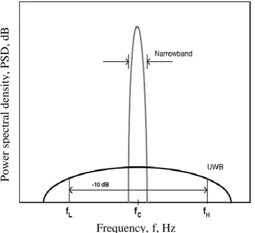
Where fH and fL are the upper and lower frequency of the -10 dB emission point, the centre frequency is defined as the average of fH and fL, i.e.
2 L H C
f f
f (2.3)
[image:51.595.170.429.437.673.2]The narrowband (NB) and UWB spectrums with the defined fC, fH and fL are shown in Figure 2-9.
Figure 2-9 Comparison of the Fractional Bandwidth η of a Narrowband (NB) and Ultra-Wideband (UWB) Spectrums
Frequency, f, Hz
P
owe
r
spe
ctra
l
de
nsit
y, P
S
29
The examples of two different common forms of UWB radio systems are provided by IEEE 802.15.3a task group i.e. (i) very short duration pulses are transmitted for conveying information, known as impulse-UWB (I-UWB), (ii) multiple simultaneous carriers are transmitted for conveying information, known as multi-carrier UWB (MC-UWB). One of these two approaches has not been standardised, leaving it on the disposal of physical descriptions of a radio to pick the more suitable approach. The same radio regulatory definitions of the FCC are employed again, a flexibility advantage of UWB standard implementation. Both approaches have their pros and cons. The basic differences between the two approaches on the basis of spectrum management are shown in Figure 2-10 [25]. The orthogonal frequency division multiplexing (OFDM) is the most popular form of multi-carrier modulation, which has become the leading modulation technique for high data rate systems.
Contrary to classic communications pure impulse radio does not use a modulated sinusoidal carrier for transmittance of information. The baseband pulses are used for this purpose. The pulses are extremely short and last for nanoseconds or less, consequently, the transmit signal bandwidth is on the order of Giga Hertz [25].
30
Figure 2-10 Comparison of impulse and multi-carrier UWB spectrums, [25]
The balance between advantages and disadvantages of I-UWB and MC-UWB is complicated to find and the standards bodies have debated over them for a long time. In a UWB system, it is most important to minimise interference in transmitted and received signals. MC-UWB is takes care of this issue by avoiding interference with its precisely
Frequency, f, GHz
R
elative Powe
r,
P
, dB
(a) Spectrum of a Gaussian monocycle-based I-UWB signal.
Frequency, f, GHz
R
elative Powe
r,
P
, dB
31
selected carrier frequencies to dodge the narrowband interference to or from narrowband systems. Moreover, the flexibility and scalability provided by MC-UWB is also relatively better; however, an additional layer of control in the physical layer is required. The impact of interference on the UWB system can be reduced by application of spread spectrum techniques in both forms of UWB [25].
Fast switching times for the transmitter and receiver are required by I-UWB. While designing the radio and antenna the transient properties must be considered. The interference to UWB systems can be resolved with the help of high instantaneous power during the brief interval of the pulse; however, doing so increases the probability of interference from UWB to narrowband systems. The RF front-end of an I-UWB system appears like a digital circuit, therefore, most problems associated with mixed-signal integrated circuits can be avoided [25]. Simple I-UWB systems are rather cost effective. In contrast, implementation of a MC-UWB front-end is complex because of the continuous variations in power over a very wide bandwidth. The job of the power amplifier becomes difficult because of this. High-speed Fast Fourier Transform (FFT) processing having significant processing power is required for OFDM.
The general detection theory assumption that the system operates in an additive white Gaussian noise (AWGN) environment poses as an additional limitation in the implementation of a UWB system. Even though under real circumstances this does not always apply to communication system and particularly to UWB systems [25]. Other signals may also exist within the UWB pass band having Gaussian noise statistics. The operation of the system is performed at higher transmit power due to these narrowband signals or the in-band interference needs to be removed.
32
2.6
UWB Signal Definition
Generation of a suitable signal is the first step in a radio communication link, these signals are later modulated with desired information. The factors that influence the appearance of UWB signal are listed as under:
1. What is permissible under the rules and regulations?
2. What level of coexistence with other services in the band is desirable? 3. The application within which the UWB signal is intended to operate.
4. What technological constraints there are from the feasibility, cost, and marketability points of view?
The UWB is not defined by the Rules and regulations of authorities such as FCC. The broad rules are defined by the regulations and the conditions for UWB communication systems to access and share a 7,500 MHz swath of spectrum extending from 3.1 to 10.6 GHz are also set by these regulations. The UWB radios need to coexist with, share, and interoperate with existing radio services to gain a place in market. It is also very important for UWB technology to be physically implemented in cost-effective integrated circuits, which will pose a challenge in performance across the frequency band [28].
33
Figure 2-11 UWB Signal Design Points, [28]
Signals are designed by shaping their properties as a function of time. There is a one-to-one mapping between what a signal looks like in time and its frequency spectrum. This relationship is mathematically expressed by the Fourier transform. The key point here is that once the signal is fully specified or described in one domain (time or frequency), its properties in the other domain are given by the Fourier transform. This property is used to define the signal in one domain and to extract the desired properties in the other domain. However, it must be noted that an important concept of UWB is that the signal is a function of time, not frequency. Frequency in UWB primarily determines propagation characteristics, such as the distance the signal can be sent, because higher frequencies are more susceptible to fading, absorption, and other effects.
34
2.7
UWB Waveform Generation (A Train of Gaussian Monocycles)
Pulsed emissions are used to produce UWB signals. A relation between very wide RF bandwidth and a narrow pulse width has been established in UWB. Traditional radio transmitters use a modulated signal which is unconverted and amplified to transmit the data; the Ultra Wideband Radio (UWB), uses pulses instead of the commonly used carrier wave for transmittance of information. Accurate pulse shaping is required by transmitters for production of the required spectrum and maximising the antenna's emission. Very precise pulse designs are required for production of emissions with flat and wide PSDs. Due to regulations and approval most of UWB developments are still in the laboratory; however, some companies have started pioneering this technology into their equipment such as avalanche transistors, tunnel diodes, and other exotic devices.
The Time Modulated UWB (TM-UWB) technology is developed by Time Domain Corporation. Ultra-short "Gaussian" monocycles with tightly controlled pulse-to-pulse intervals, commonly known as Pulse Repetition Interval (PRI) are emitted by the TM-UWB. The pulse widths usually range between 0.2 and 1.5 nanoseconds and the range for PRI is 25-1000 nanoseconds. PRI is different for each pulse and depends on two factors: an information signal and a channel code that is a Pseudo-Random Noise (PN) sequence. Different pulse shapes were proposed for UWB, ranging from the rectangular pulse, to the bell shaped Gaussian pulse [52]. The Gaussian pulses and their derivatives are mostly used pulses in UWB systems today, particularly in communication and measurement systems because they have effective simultaneous high time and frequency resolution, and often referred as monocycles [13]. Gaussian monocycles are obtained when successive derivatives of the basic Gaussian waveform are taken. A typical definition of a Gaussian function is out line in [25] [53] and shown in equation (2.4)
2 2
2 ) (
2 1 )
(
t e t
G
35
Where, is the mean and is the variance of the statistical distribution characterised by the function. Considering 0, we have the definition of the so-called "zero-order Gaussian pulse" 2 2 2 2 1 ) ( 0 t e t G p
(2.5)
The other UWB waveforms can be obtained by differentiating
(
)
0
t
p
G w.r.t "t", i.e.
) ( 0 ) ( t G p n dt n d t n G
p (2.6)
Where n is the order of the derivatives.
The following formulae show the first five derivatives of the Gaussian pulse [54]
2 2 2 3 2 ) ( 1 t e t t G p
, (2.7)
2 2 2 3 2 2 2 1 ) ( 2
e t
t t G p
, (2.8)
2 2 2 5 2 2 3 3 ) ( 3
e t
t t t G p
, (2.9)
2 2 2 5 2 4 4 2 2 3 3 ) ( 4
e t
t t t G p
, (2.10)
2 2 2 7 2 4 5 2 3 10 15 ) ( 5
e t
t t t t G p
36
The pulse length Tp is related to the variance through the linear transformation outline in [25] as
2
p
T (2.12)
The value of practical pulse is almost negligible outside the interval {-Tp/2, Tp/2}, and most of the pulse's energy, is within this range. For the analysis of the spectral behaviour of these waveforms, following equation is used to calculate the Fourier transform as described in [54]
22 T f Te T t e F (2.13)
Then, considering T 2 one can get
2 2 2 2 2 2 2 2 1 ) ( 0 f e f e f GP
(2.14)
The property given below can be used to calculate the Fourier transform of the first five derivatives of the Gaussian pulse as described in [54]
( )0 2
)
(t j f nPG f
n G p n dt n d
F
(2.15) Thus giving
22 2 ) ( 1 f e f j f G
P , (2.16)
2 2
24 ) ( 2 f e f f G
P , (2.17)
3 2
28 ) ( 3 f e f j f G
37
4 2
216 ) ( 4 f e f f G
P , and (2.19)
5 2
232 ) ( 5 f e f j f G
P . (2.20)
The centre frequency fc(n) of the spectra of the n-th derivative of the Gaussian pulse can be defined as the point where the spectrum reaches its maximum, satisfying the equality
( ) 2 ) ( ) ( 2 ) ( n c f f n G P df n c f f n G
P (2.21)
According to this relationship, it can be noticed that fc(n) increases proportionally with the square root of the derivative order, as described in [54] i.e.,
p T
n n
c
f( ) (2.22)
Hence, the centre frequency of the first five derivatives of the Gaussian pulse can be summarised in Table 2-1 as
Waveform name Centre frequency Gaussian 1st derivative
p T c
f(1) 1/
Gaussian 2nd derivative fc(2) 2/Tp Gaussian 3rd derivative fc(3) 3/Tp Gaussian 4th derivative fc(4) 2/Tp Gaussian 5th derivative fc(5) 5/Tp
38 In Figure 2-12 the time behaviour of ( )
0
t G
p and its first five derivatives are represented for Tp 0.5ns, as an example. For the analysis of the time properties of each order, Figure 2-12a represents the zero, first, and second order Gaussian pulses, the third, fourth, and fifth order Gaussian pulses are shown in Figure 2-12b. The corresponding spectral behaviour of all the five order Gaussian pulses in the frequency domain for normalised amplitude represented in volts is represented in Figure 2-13a and their spectral behaviour for normalised amplitude represented in dB are shown in Figure 2-13b.
Figure 2-12 shows that even though the pulses are very narrow, their amplitudes show variations across time, the side’s lobes become negligible in the frequency domain. Alternatively, Figure 2-13 shows that the extra shift in the nominal centre frequency of each pulse in the frequency domain to the higher frequencies is in accordance with the formula in equation (2.22) for a specified pulse length Tp.

![Figure 2-10 Comparison of impulse and multi-carrier UWB spectrums, [25]](https://thumb-us.123doks.com/thumbv2/123dok_us/8688504.876566/53.595.118.443.82.581/figure-comparison-impulse-multi-carrier-uwb-spectrums.webp)
![Figure 2-11 UWB Signal Design Points, [28]](https://thumb-us.123doks.com/thumbv2/123dok_us/8688504.876566/56.595.126.485.130.414/figure-uwb-signal-design-points.webp)