A Survey of Free Space Optical Communication Network
Channel over Optical Fiber Cable Communication
Akhil Gupta, Pankaj Anand, Rohit Khajuria, Sonam Bhagat, Rakesh Kumar Jha
School of Electronics and Communication Engineering Shri Mata Vaishno Devi University
Katra, Jammu and Kashmir, India
ABSTRACT
In the recent past, free-space optical communication (FSO) proved to be an important replacement to radio frequency communication. In optical fiber cable communication, there is a disadvantage that optical fiber gets damaged in a long distance installation. Radio frequency communication also deals with limitations of bandwidth and data rate. In this paper, a brief description about free space optical (FSO) communication and its connectivity with central cellular network is explained. This paper also provides the information about the role of free space optics in the central cellular network. It contains an RF network, which has connections within the Radio Access Network (RAN) and the Central Network (CN) for connecting the mobile user subscriber to the Public Switched Telephone Networks (PSTN) and Internet. Moreover, free space optical communication paves the way for a high bandwidth requiring applications with license free operation, high transmission security, full duplex transmission and protocol transparency will give a broader view to free space optical communication.
Keywords
FSO, RAN, CN, PSTN, PAT.
1.
INTRODUCTION
Optical communication system can also be named as optical telecommunication system. It was started in 1970 and works in 800nm-1600nm wavelength range. In this system, light is used for communicating the information. The bandwidth of the optical communication system is 1000 times higher which helps in easy launching of the objects. In this system, many users communicate at the same time due to high bandwidth easily. In the present scenario, optical communication supports 300 THz bandwidth [1]. In optical communication system, the task is performed by using three parameters: Transmitter, Channel and Receiver.
The function of the transmitter is to encode the message electrical signal into an optical signal. Semiconductor devices are commonly used in optical transmitters like LED (Light-Emitting Diodes) and LASER diodes. The difference between the two is that, LED is used for short range communication and produces incoherent light whereas LASER is used for long range communication and produces coherent light. Semiconductor optical transmitters should be highly efficient, compact and reliable. It can be directly modulated at high frequencies [1]. A semiconductor LED emits light through spontaneous emission. LEDs are very useful for low-cost applications because of its simple design. A semiconductor
The channel takes the signal to its destination. It is a flexible and transparent fiber made up of high quality silica or plastic. It works similarly as a waveguide for transmitting light from one end of the fiber to another. It is mainly used for long distance transmission and with higher data rates than wire cables.
The receiver generates the message signal from the received input signal. The photo detector is the prime component of the optical receiver which converts light into electricity by using the photoelectric effect. It is a semiconductor based photodiode. PN photodiodes, PIN photodiodes and avalanche photodiodes are the types of photodiodes. The coupling combination of electrical converters, trans-impedance amplifier and a limiting amplifier produces a digital signal in the electrical domain from the incoming optical signal, which may be attenuated while passing through the channel [8, 9-11].
Optical fiber communication has some advantages because of which it has been used for a long time. It has extremely high bandwidth and along with this, many users communicate easily at the same time. It has a low manufacturing cost with Bit Error Ratio (BER) of 10-6 [12]. But it has some disadvantages also that it can only be done through point to point communication and propagation of light is unidirectional. But the disadvantages of optical fiber communication are removed by Free Space Optical Communication. It is defined as the technology which uses light for propagating in vacuum or air to transmit data for computer networking. This technology is helpful because of high cost due to the impracticality of physical connections. It is easy to deploy and has high bit rates and low bit error rates. It is license free and used for long range operation. But it has some ill effects like Atmospheric absorption, Beam dispersion and Inference from background light sources
The remaining paper is organized as follows. In section II, a detailed description about free space optical communication is given and section III involves the application of free space optical communication in the central cellular network. The paper is concluded in section IV.
2.
FREE SPACE OPTICAL
COMMUNICATION
lead to a new mode of communication called as free space optical communication. Since optical fiber cabled infrastructure has failed to reach a fewer cellular end point. But this limitation is removed by free space optical communication. It uses free space for the communication purpose, so also known as fiberglass optics or optical wireless
[13]
.
A free space optical system uses simple on-off keying as modulation format which allows a free space optical system to be designed as bandwidth and protocol transparent physical layer connection. In order to implement a free space optical network, we need to have following two crucial components as a part of it, radio access network (RAN) and central network (CN). RAN provides the connectivity between the mobile users and CN by using RF frequency signal as a medium. RAN uses a base station and base controller, while CN provides the PSTN for mobile to mobile telephony [14].
The microwave RF signal is also used as a source of connectivity.
Free Space Optical system has some advantages over the optical fiber communication system:
Ease of deployment: FSO system has replaced the infrastructure based OFC system without letting its performance down. Moreover, it is also cost effective method and free from hassles of digging and burring the cables.
License free operation: FSO system requires no RF license so it can be easily deployed. It is easily upgradable and its open interface support equipment from a variety of vendors, which helps enterprises and service providers protect their investment in embedded telecommunication infrastructure.
High speed and bit rate: FSO communication is incredibly fast and allows a data rate of 2.5 GB/s. This is an ample amount of BW for transfer of files between two ends. Moreover, these rates are expected to increase up to a whopping are about 10 GB/s. Since in FSO, beam confinement is so crucial and effective that two beams operate almost independently and such diversity between two information carrying beams provided virtually unlimited degree of frequency reuse in any typical environments.
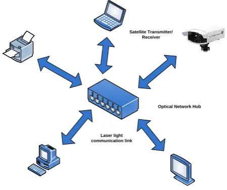
Security: FSO is a very secure wireless system of communication. Due to tight beam or beam confinement nature required for transmitting a signal, a signal via a laser to RX it is, it is practically impossible to crack that information in the network. Since the laser beam cannot be detected by a spectrum of RF meter so it is one more credential in favor of FSO’S secure communication. Moreover, one has to be in the line of sight between RX and TX to be able to over drop the information. However, if it is possible, then it would to receiving site have lost connections there are no security upgrades that are required for FSO. Figure 1 describes a general free space optical network.
Satellite Transmitter/ Receiver
Optical Network Hub
[image:2.595.314.539.73.261.2]Laser light communication link
Fig 1: A General Free Space Optical Network
Every technology comes with some weak points also which will make alive the research in the topic. FSO has some weak points as follows:
Distance: The distance up to which an FSO system communicates is not so large and is limited within 2 km range. Although it is a power full system with great throughput, but distance limitation is a big asset to its use.
Line of sight communication: A tight laser beam or a more confined beam is critical in case of FSO, but LOS in FSO is affected by another factor as:
o Fog: Dense fogs mainly affect the beam confinement nature. It either completely traps the beam or decreases its intensity after multiple refractions, scattering and absorption. A method to reduce this is to use it for short distances.
o Atmospheric effect: The various atmospheric effects that can really change the nature of the laser beam or to reduce its power are absorption of the water molecule, scattering by suspending particles in nature physical obstructions or constructions in the way of LOS and also the solar interference. Scattering occurs when the wavelength of light collides with a particle. The type of scattering which occurs decided by the wavelength of light:
If wavelength < scatterer size (Rayleigh scattering)
If wavelength > scatterer size (Mie scattering)
3.
APPLICATION OF FREE SPACE
OPTICS IN CENTRAL CELLULAR
NETWORK
Free space optical products are embedded with cellular networks as line of sight successor of earthly links in the central cellular network. Free space optic products having benefits of no cabling and no spectrum licensing. They offer high speed data rate, with the capacity of optical fiber. The main disadvantages of free space optic communications used in practice are link reliability due to weather, and distance [15]. These parameters restrict free space optic links to a few kilometers.
The laser has an important property of highly directional beams. Free space optical system receiver is designed in such a way to get a small divergence and concentrate less optical energy on a receiver. Each and every optical transceiver is pointed in a stimulating manner to another in the communication process. Because of the environmental effects like atmospheric pressure, air and thermal loading of equipment and building structure, free space optical system need to implement Pointing, Acquisition, and Tracking (PAT) subsystems [16]. The more difficult task is to develop PAT but in RF communication transmitter and receiver have main equipment. Travelling from point to point is non- trivial. The divergence of the transmitted beam and the receiver field-of-view has to be greater than the beam jitter in order to get exact data.
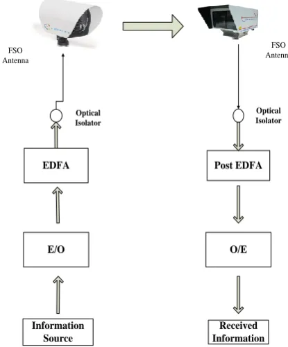
Conventional Free space optic systems, first fiber sending end transceiver convert an electrical signal into an optical signal. Then in same side electrical signal is amplified by a laser driver providing enough current to drive the laser diode. A modulated light wave of laser diode is directed through the channel to the corresponding receiver which focuses the light beam onto a photo-detector [17, 18-21]. At last the optical signal converted back into an electrical signal. Figure 2 illustrates the free space optical communication system
Information Source
O/E
Received Information E/O
Post EDFA EDFA
FSO Antenna
FSO Antenna
Optical Isolator
Optical Isolator
In wireless optical communication systems, light emitted directly from a fiber termination to free space through an optical antenna. At the receiver end, the transmitted optical beam is focused, using the receiver optics, directly to a fiber and then sent down the fiber for detection. Hence the conversion of a signal from electrical to optical and optical to electrical is removed, which give rise to bandwidth and protocol transparent communication link and is also much easier to integrate with cabled infrastructure.
We have studied for a long time about radio frequency and free space optics because of their matching nature. Radio and free space link communication, both have the capacity to use both at a time. The combine use of both will have an advantage on a single communication system. Both are affected by environment crises. Free space optic links are severely attenuated in foggy conditions, and microwave RF frequencies are significantly attenuated by rain, due to scattering that happens in case of rainy season. Optical wireless allows high data rate and high throughput which is advantageous in delay inconsiderate applications [22].
The transition from wired to the wireless network user by maintaining the connectivity irrespective of user’s mobility and geographical restrictions is fulfilled by the radio access network. With increasing demand or expect levels of the mobile user, the radio access network alone is not been able to provide increased capacity and increased coverage with limited radio resources. In earlier communication systems, many base transceiver stations were connected to a Base Station Controller, which takes the responsibility of Radio Resource Management. But in an LTE advanced communication system, eNodeBs are responsible for Radio Resource Management decisions. Suitability of free space optical links in the Radio access networks is accessed in this communication system.
Newly developed cellular systems will support the user with shorter distance between the user and the operating fixed networks. This can be achieved by increasing the number of antennas to 4 times while shifting from 3G to 4G technologies. Coordinated Multipoint transmission and reception, relay networks and distributed antennas are the cost effective alternatives that will reduce to deal with methodologies like cell splitting and sectoring, which will increase the signal to noise ratio to and from mobile users. Free space optical communication will present a pleasing option of transmission of RF signals over optical fiber to link wireless network connections. This is termed as Radio over Fiber or RF Photonics [23]. In this method, optical carriers are used to place analog Radio Frequency signals and then transmitted through optical fiber cables having high capacity. In optical fiber transmitter modulation procedure, the optical carrier is modulated with the radio signal. Optical fiber offers a very small amount of attenuation and is free from multipath fading. It is also protected from electromagnetic interference. The restriction in installation of optical fiber cables has proven the usefulness of free space optic communication systems that are capable of replacing Radio over Fiber links.
[image:3.595.62.270.486.737.2]The small service areas with low transmit power Pico-base stations are known as Pico cells [24]. They will reach out for
less mobile subscribers which are inside a building and provide them with services. Since telecommunication companies have spent a large amount of their financial resource for providing optical fiber connectivity between countries and cities but this connectivity is still unavailable for many high data throughput requirement buildings. Thus a significant problem of “last mile” is still present. Since it is not possible always to lay down an optical fiber, as it is costly as well as time-consuming. So Free space optic communication systems are a solution of the “last mile” problem, mainly in overpopulated urban areas.
4.
CONCLUSION
The design of advance RF network is reliable for complex meshes and good for a free space optics prospect. Generally meshes are considered for short link displacements between antennas. This short link provides reliability, speed, and diverse nature of signal in temporary and bad weather conditions. Free space optical link is more generic but somewhat problematic, but we can achieve some invariable applications. The mobility decreases as the distance increases, but it can be removed by using spherical antennas. There is work going on in a positive direction to increase the system reliability and continuity, but the size and complexity of the system also needs a solution in the near future. There is also a need of stability in connectivity of mobile users because of indoor and quasi-diffusion transmission. The main issues that are hindering the growth are temperature loading effects, bad weather conditions; storms, building, and vibrations. As optical fibers have high bandwidth, which is the main factor why still optical cables are used for long distance transmission. Free space optical communication is for suitable for short distance up to a maximum of 4 km. Due to complexity of access points, Opportunities will grow for short link transmission.
5.
REFERENCES
[1] S. Ghosh, K. Basu and S. K. Das, "An architecture for next generation radio access networks," IEEE Network, vol. 19, 2005, pp.35-42
[2] J. Hou and D. C. O'Brien, "Vertical handover-decision-making algorithm using fuzzy logic for the integrated Radio-and-OW system," Wireless Communications, IEEE Transactions on, vol. 5, 2006, pp. 176-185.
[3] S. Ghosh. "Emergent technology based Radio Access Network (RAN) design framework for next generation broadband wireless systems," M.S. thesis, Dept. Comp. Sci. and Eng., Univ. Texas at Arlington, 2004.
[4] T. Kamalakis, I. Neokosmidis, A. Tsipouras, S. Pantazis and I. Andrikopoulos, "Hybrid free space optical/millimeter wave outdoor links for broadband wireless access networks," in Personal, Indoor and Mobile Radio Communications, IEEE 18th International Symposium on, 2007, pp. 1-5.
[5] M. Safari and M. Uysal, "Relay-assisted free-space optical communication," in Signals, Systems and Computers, Forty-First Asilomar Conference on, 2007, pp. 1891-1895.
[6] J. Akella, C. Liu, D. Partyka, M. Yuksel, S. Kalyanaraman and P. Dutta, "Building blocks for mobile free-space-optical networks," in Wireless and Optical
Communications Networks, Second IFIP International Conference on, 2005, pp. 164-168.
[7] O. Bouchet, M. El Tabach, M. Wolf, D. C. O'Brien, G. E. Faulkner, J. W. Walewski, S. Randel, M. Franke, S. Nerreter, K. D. Langer, J. Grubor and T. Kamalakis, "Hybrid wireless optics (HWO): Building the next-generation home network," in Communication Systems, Networks and Digital Signal Processing, 6th International Symposium on, 2008, pp. 283-287
[8] D. O'Brien, "Cooperation in optical wireless communications," in Cognitive Wireless Networks: Concepts, Methodologies and Visions Inspiring the Age of Enlightenment of Wireless Communications, F.H. P. Fitzek and M. D. Katz, Eds. Springer, 2007, pp. 623-634
[9] J. P. Javaudin and M. Bellec, "Technology convergence for future home networks," in Wireless Days, 2008, 1st IFIP, 2009, pp. 1-5
[10] R. Ramirez-Iniguez and R. J. Green, "Indoor optical wireless communications," in Optical Wireless Communications, IEE Colloquium on, 1999, pp. 14/1-14/7.
[11] R. J. Green, H. Joshi, M. D. Higgins and M. S. Leeson, "Recent developments in indoor optical wireless systems," IET Communications, vol. 2, 2008, pp. 3-10.
[12] Gupta, Akhil. "Improving Channel Estimation in OFDM System Using Time Domain Channel Estimation for Time Correlated Rayleigh Fading Channel Model." International Journal of Engineering and Science Invention, vol. 2, issue 8, pp. 45-51, August. 2013
[13] K. Kazaura, K. Wakamori, M. Matsumoto, T. Higashino, K.Tsukamoto and S. Komaki, "RoFSO: A universal platform for convergence of fiber and free-space optical communication networks," Communications Magazine, IEEE, vol. 48, 2010, pp. 130-137.
[14] R. Ramirez-Iniguez, S. M. Idrus and Z. Sun, Optical Wireless Communications: IR for Wireless Connectivity. CRC Press, 2008
[15] J. C. Juarez, A. Dwivedi, A. R. Mammons, S. D. Jones, V.Weerackody and R. A. Nichols, "Free-space optical communicationsfor next-generation military networks," Communications Magazine,IEEE, vol. 44, 2006, pp. 46-51.
[16] D. M. Jeganathan and D. P. Ionov. (2001, Dec 27). Multi-Gigabits per-second optical wireless communications [Online]. Available: www.freespaceoptic.com.
[17] S. S. Muhammad, B. Flecker, E. Leitgeb and M. Gebhart,"Characterization of fog attenuation in terrestrial free space opticallinks," Optical Engineering, vol. 46, 2007, pp. 066001-1-066001-10
[18] C. C. Davis, I. I. Smolyaninov and S. D. Milner, "Flexible optical wireless links and networks," Communications Magazine, IEEE, vol. 41, 2003, pp. 51-57.
[20] I. Kim and E. Korevaar, "Availability of free space optics (FSO) and hybrid FSO/RF systems," Optical Wireless Communications IV, vol. 4530, 2001, pp. 84-95.
[21] K. Kazaura, P. Dat, A. Shah, T. Suzuki, K. Wakamori, M. Matsumoto, T. Higashino, K. Tsukamoto and S. Komaki, "Studies on a next generation access technology using radio over free-space optic links," in Next Generation Mobile Applications, Services and Technologies, 2008, pp. 317-324.
[22] J. S. Seybold and I. NetLibrary, Introduction to RF Propagation.Wiley Online Library, 2005
[23] P. T. Dat, A. M. Shah, K. Kazaura, K. Wakamori, T. Suzuki, K.Takahashi, M. Matsumoto, Y. Aburakawa, T. Nakamura, T.Higashino, K. Tsukamoto and S. Komaki, "A study on transmission of RF signals over a turbulent free space optical link," in Microwave Photonics, 2008, pp. 173-176.