Rope Climbing Robot
K. Vidyasagar
Dept.of ECE,SSIT Sathupally,T.S,.India.
Sk. Ahmadsaidulu
Dept.of ECE,SSIT Sathupally,T.S,.India.
M. Sumalatha
Dept.of ECE,SSIT Sathupally,T.S,.India.
ABSTRACT
With the advancement in mechatronics era the wireless communication will play a vital role in robotic applications. Many researchers are focusing to develop the rope climbing robots (RCR). This paper discussed the vertical movement of the rope climbing robot. The method adopted to RCR results reliable values to meet the challenges of the military operations. Suitable calculations are done to select the driving motor. The Torque, Angular velocity, and power required for driving the load. Both linear motion of the RCR and rotational motion of the Motor shaft is estimated. The communication between the transmitter control room and the receiver at the RCR has established using Offset Quadrature phase shift keyed modulation stream (OQPSK) applied on IEEE 802.15.4. A surveillance camera positioned on the top surface of the RCR is used to capture the targeted location. The acquired information is transmitted to the control room for further processing. This developed RCR is best suited for military operation to target the anti social elements at risky situations.
General terms
Micro controller, D.C Motor driver
Keywords
Rope climbing robot, Torque, angular velocity, wireless communication
1.
INTRODUCTION
The rapid growth of technology is enabling the researchers to meet the challenges of the society. Considering the speed and Flexibility to the demands, especially the new innovation in the electronic era is totally dominating the requirements in association with the mechanical structures, the combination of mechanical structures and electronics is labeled as mechatronics. This is the diversified area where one can develop a system which fulfils day to day requirements. The system is labeled as a robot which will be guided by an operator or independently i.e. Knowledge based.
A miserable incident at ‘Taj’ International hotel, took place at Mumbai in INDIA. Identifying the anti social elements is a challenging task motivated us to develop a rope climbing robot accompanied by surveillance camera. A cordless cam installed at the top of the surface can able to capture the position of the antisocial elements and can transmit to the ground station for further operation. Two 10 rpm and one 100 rpm high torque D.C Motors are used to drive the robot in both up and down directions. The maximum amount of load driven by the motor is estimated by considering the torque and power required to uplift the body of the RCR. The controlling unit of a robot consists of a transmitter and a receiver. AT 89S52 Microcontroller used to regulate the sliding motion of the robot. Port ‘1’ is used as an input port to control the motion of the motors in the receiver section using Limit switches. A control switch is used to provide the necessary inputs to regulate the motion of the robot to the upward and downward directions. Differential drive system motors with
plastic gears are used for smooth functioning of the robot. While moving the upward direction stability also needs to be considered. Hence gripper assembly of the robot and motion smoothness is two parameters having significance in rope climbing robot. The designed robot can move either in upward direction and downward direction. The movement of the robot is manually controlled through a wireless transceiver. The robot can be positioned at required location by using the transmitter section. The stop and start of the robot can be driven remotely. This robot is designed for military applications to enable them have surveillance capability. This can be adopted for the risky areas, and difficult to accomplish by a human being.
2.
LITERATURE SURVEY
15 some conditions are not taken into account and functionally of
such robots become inefficient in those conditions. Online static equilibrium analysis method proposed to control the movement of a multi-legged rope climbing robot (RCR) in typical conditions [14] In this paper the robot developed to move in the vertical direction. Specifically the robot is climbing vertically with the support of a rope. In [15] A cable inspection robot is developed. They developed the concept in three steps.
1. An inspection climbing model robot is designed supported by an independent spring. 2. Ratio of vertical height of the obstacle to the radius of the climbing wheel is determined. 3. Using the finite element method driving wheel rubber bearing capacity is studied. The climbing performance is studied through simulation by considering the positive pressure from the passive spring and the swinging angle of the passive wheel.
3.
THEORETICAL CALCULATIONS
For stable position of the RCR The required spinning force (torque) of the motor is estimated. The robot needs to apply more torque to move upward direction to overcome the gravity. Hence it exerts more force on the robot body to enhance the acceleration in-order to lift it up. The shaft length is proportional to the torque required. The torque at the arm joint is limited hence we chosen shorter arm to lift more weight. The Torque required to lift the RCR is proportional to its weight. More torque required for heavier loads. The measured weight of the RCR body is 23.535960068736 Newton, and the shaft length is 0.03 meters.
Torque required = Force * Distance = 23.5359600*0.03= 0.7060 Newton –Meters.
The power is also significant factor to consider. Since the amount of power that the RCR will output limits the rate at which the robot can lift its body in the upward direction. Hence more power cause to lift the body quickly.
For RCR Body Linear motion
The power [watts] = Force [Newton] * velocity [Meter/ Second]
The estimated required power = 23.5359600 * 0.0818 = 1.92524 watts.
For angular motion of the motor shaft
The angular velocity of motor under no load is 100 RPM.
The calculation of power is the product of torque and the rotational distance per unit time.
Prot = M* W
Where
Prot = Rotational mechanical power
M= Torque
W= Angular velocity
Angular velocity Wrad /sec = 100 * [ 2*Π / 60 ] = 10.46 rad / sec
Power required to drive a torque load of 0.7060 Newton / meter
= Torque Load* 100 rpm * conversion factor
= 0.7060 *100 * 0.1047= 7.3918 Watts
Rotational mechanical power P rot =7.3918 Watts
Output shaft torque M = 0.7060
Motor current estimated (I) = M /K
Where K is torque constant = 1.22 NM/A
The resistance (R) of the motor = 3.3 Ohms
Drive voltage U = R*I + K* W
Where w is Angular velocity
Motor current I = 0.57 A
Estimated Drive Voltage = 14.64 V dc
Rated voltage = 15 V dc
4.
COMMUNICATION
Low power short range communication is established between the Rope climbing robot control unit and the control room using IEEE 802.15.4. Offset Quadrature phase shift keyed modulation stream (OQPSK) with 2.4 G Hz is used for transmitting the information to the remote control section of the robot. Port 3 is used to transmit and to receive the data. The received signal is used to drive the robot in up and down directions. This paper focused on controlling the robot remotely.
4.1
Transmitter Section
The control circuits are simulated using proteus software and then the hardware circuit is developed. Three push buttons are used to control the RCR remotely. Two push buttons for upward, downward movement and another one to stop the RCR at targeted place. Once the RCR is stable the captured information is transmitted to the control room. The Image is pre processed for precisely targeting the anti social elements in military operations.
Fig.1 Simulation block diagram of the transmitter
The switch connected to port 1.0 and port 1.3 is used for body motor ‘1’ to move in the clockwise direction which in turn moves the gripper part in the upward direction and anti clockwise direction to move in the downward direction respectively. The switch connected to port 1.1 and port 1.2 is used for gripper motor to open (clockwise) and close (anti clockwise) state of the gripper. The switch connected to port 1.4 and port 1.7 is used for body motor ‘2’ to move in the anti clockwise direction which in turn moves the gripper part in the upward direction and clockwise direction to move in the downward direction respectively. The switch connected to port 1.5 and port 1.6 is used for gripper motor to open (anti clockwise) and close (clockwise) state of the gripper.
BAT1 9V D1 DIODE D2 DIODE D3 DIODE D4 DIODE VI 1 VO3
G ND 2 U1 7805 C1 1uF C2 100uF R1 1k D5 LED-BIBY 12 v+ 5v+ D 7 1 4 D 6 1 3 D 5 1 2 D 4 1 1 D 3 1 0 D 2 9 D 1 8 D 0 7 E 6 RW 5 R S 4 V SS 1 V DD 2 V EE 3 LCD1 LM016L
d0d1d2d3d4d5d6d7
en rw rs R3 100k T1IN 11 R1OUT 12 T2IN 10 R2OUT 9 T1OUT14 R1IN13 T2OUT7 R2IN8 C2+ 4 C2-5 C1+ 1 C1-3 VS+2 VS-6 U3 MAX232 C6 1nF tx rx C7 1nF C8 1nF C9 1nF 5v+ ERROR TXD 3 RXD 2 CTS 8 RTS 7 DSR 6 DTR 4 DCD 1 RI 9 P1 COMPIM XTAL2 18 XTAL1 19 ALE 30 EA 31 PSEN 29 RST 9 P0.0/AD039 P0.1/AD138 P0.2/AD237 P0.3/AD336 P0.4/AD435 P0.5/AD534 P0.6/AD633 P0.7/AD732 P1.0 1 P1.1 2 P1.2 3 P1.3 4 P1.4 5 P1.5 6 P1.6 7 P1.7 8 P3.0/RXD10 P3.1/TXD11 P3.2/INT012 P3.3/INT113 P3.4/T014 P3.7/RD17 P3.6/WRP3.5/T11615 P2.7/A1528 P2.0/A821 P2.1/A922 P2.2/A1023 P2.3/A1124 P2.4/A1225 P2.5/A1326 P2.6/A1427 U2 AT89C51 d0 d1 d2 d3 d4 d5 d6 d7 rs rw en rx tx 23456789
Fig.2 Hardware implementation of Transmitter control
4.2
Receiver Section
Fig.3 Simulation block diagram of the receiver
At 89S52 is used as a controller at the receiver section. Port 2 of the controller connected to the H-Bridge Motor driver which can drive two motors simultaneously. Port ‘0’ is used to interface the Liquid crystal display. The pins RS, R/W and EN are connected to Port 2.0, port 2.1 and port 2.2 respectively. Port 2 pins 0,1,2,3 are used to connect with IN1, IN2, IN3, and IN4 of the motor driver 1. Port 2 pins 4,5,6,7 are used to connect with IN1, IN2, IN3, and IN4 of the motor driver 2. The motion of the body motor ‘1’ stops when the switch connected to port 0.0 and 0.1 is pressed.
The motion of the body motor 2 stops when the switch connected to the port 0.2 and port 0.3 is pressed. The gripper motor 1 stops its motion when the switch connected to port 0.4 is pressed.The gripper motor 2 stops when the switch connected to the port 0.5 is pressed. Port 3.1 and port 3.0 are used for transmitting and receiving the data.
Fig.4 Hardware implementation of receiver control
5.
METHODOLOGY
This paper used two Push buttons named as release button and grab button. The release button is to be pressed on the control panel to release both grippers and to pass through the rope. Grab Button is to be pressed on the control panel to stabilize the robot body on the rope. Gripper A is grabbed and gripper B is released then the robot moves upwards towards the gripper A. Now the gripper B is grabbed and gripper A is released. Then the sliding motor A provided with high torque moves upwards through the rope. The necessary steps are stated to move the robot in the upward and downward directions.
Step1: Release down gripper B
Step2: Move gripper motor B upwards.
Step3: Grab down gripper B
Step4: Release upper gripper A
Step5: Move sliding motor A upwards.
Step6: Grab Upper Grip A
Step7: Go to step 8 to move down wards.
Step8: Release upper gripper A
Step9: Move sliding motor A downwards
Step10: Grab upper Gripper A
Step11: Release down gripper B
Step 12: Move gripper motor B downwards
Step13: Grab down gripper B
6. RESULTS AND ANALYSIS
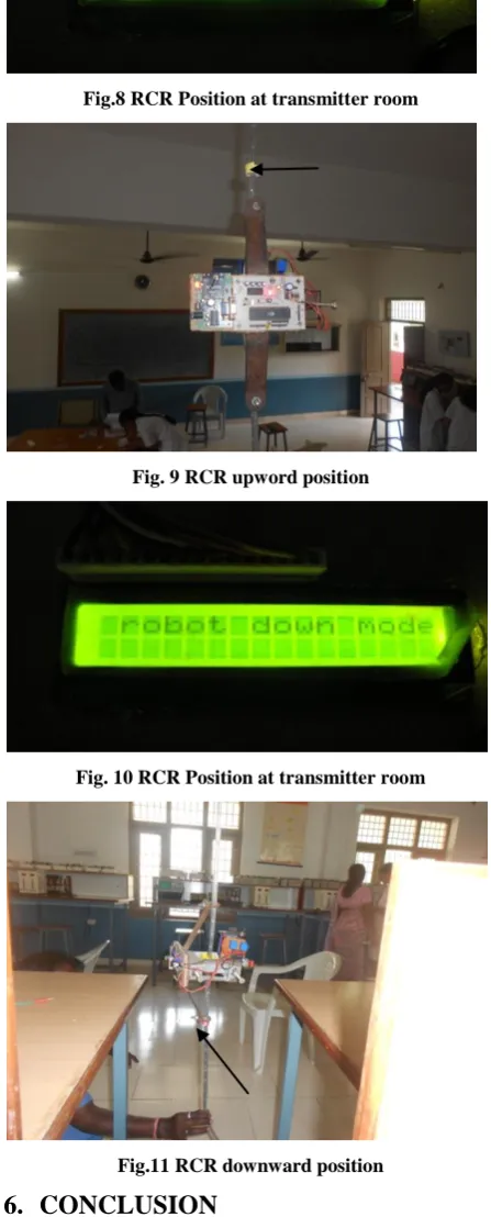
The experiment was conducted by keeping the RCR travel distance is 1.8 Meters. We fixed the maximum uplift position and maximum down position. The velocity of the vertically down movement of the RCR is considerably greater than the upward movement. An estimated torque of 0.7060 Newton – Meters is limiting the velocity to drive a load of 23.5359600 Newton in the upward direction. By increasing the Rotational mechanical power of 7.3918 Watts the velocity of the RCR can be favorably raised to a considerable value. Initially the experiments were conducted with 500 rpm D.C motor. While climbing the RCR we encountered two limitations. The RCR is failed to stop at the targeted position owing to its speed. And mostly the entire RCR equipment entered into unstable region resulting blurred images while capturing the targeted location. The developed RCR is best suited for military applications to identify the targeted anti social elements to safeguard the human life. Heavy duty four plastic gears used to hold the rope. The gripper had shown in the fig.6 exhibits fine results while moving the robot both upward and downward directions. Fig.7 is the stationary position of the RCR. Fig.8 and Fig.10 represents the actual positional status of the robot at the control room displayed on the LCD. Fig. 9 represents the upward movement of the robot reached to yellow marked point. Fig.11 represents the downward motion of the robot reached to the pink mark point. The upward motion of the robot is opposed by the Gravitational force. We considered a single motor to drive the load of 23.5359600 Newton. Results the velocity becomes very small. Two Symmetrical motors with H-bridge driving circuit may meet the challenges in order to improve the velocity in the upward direction.
BAT1
9V
D1
DIODE
D2
DIODE
D3
DIODE
D4
DIODE VI 1 VO3
G
N
D
2
U1
7805
C1
1uF
C2
100uF
R1
1k
D5
LED-BIBY
V1 v2
IN1 2
OUT13 OUT26 OUT311 OUT414 IN2 7
IN3 10
IN4 15
EN1 1
EN2 9
VS 8 VSS
16
GNDGND
U2
L293D a
b
XTAL2 18
XTAL1 19
ALE 30
EA 31
PSEN 29
RST 9
P0.0/AD039 P0.1/AD138 P0.2/AD237 P0.3/AD336 P0.4/AD435 P0.5/AD534 P0.6/AD633 P0.7/AD732
P1.0/T2 1
P1.1/T2EX 2
P1.2 3
P1.3 4
P1.4 5
P1.5 6
P1.6 7
P1.7 8
P3.0/RXD10 P3.1/TXD11 P3.2/INT012 P3.3/INT113 P3.4/T014 P3.7/RD17 P3.6/WRP3.5/T11615 P2.7/A1528 P2.0/A821 P2.1/A922 P2.2/A1023 P2.3/A1124 P2.4/A1225 P2.5/A1326 P2.6/A1427
U1
AT89C52
C7
1nF
C8
1nF
X1
CRYSTAL
C9
1uF
R2
110R
a b
rx tx T1IN
11 R1OUT 12
T2IN 10
R2OUT 9
T1OUT14 R1IN13 T2OUT7 R2IN8 C2+ 4
C2-5 C1+ 1
C1-3
VS+2 VS-6
U3
MAX232 tx
rx
ERROR
TXD 3
RXD 2
CTS 8
RTS 7
DSR 6
DTR 4
DCD 1
RI 9
P1
COMPIM
C3
10u
C4
10u
C5
10u
C6
10u
17
Table.1 Experimental readings of Distance Vs velocity
S.No Position of the
rope
Direction of movement
Distance (Mtr)
Time (sec)
Velocity ( M/ S )
1 Vertical UP 1.8 22 0.0818
[image:4.595.48.287.84.583.2]2 Vertical Down 1.8 9 0.2
[image:4.595.314.538.150.705.2]Fig.5 Distance Vs velocity graph
Table.2 Mechanical parameters
S.No Type of Motion
Torque ( N/M)
Velocity (M/S)
Mechanical Power (watts)
1 Linear 0.7060 0.9 21.18
2 Rotational
shaft of the motor
0.7060 10.46 rad
/ sec
7.391
Fig.6 Rope gripper mechanism
Fig.7 Stationary position of the RCR
Fig.8 RCR Position at transmitter room
Fig. 9 RCR upword position
Fig. 10 RCR Position at transmitter room
Fig.11 RCR downward position
6.
CONCLUSION
The rope climbing robot was developed to safeguard the human from the anti social elements. The developed system shows reliable results while positioning the device at targeted places. This developed model is best suited for military operations.
0 0.5 1 1.5 2
[image:4.595.52.289.280.750.2]In future this RCR System is proposed to power with image processing. The acquired image is to be re processed to remove the noise using median filters and also the inputted image is to be resolute to a considerable level. So that precise identification of the anti social elements may be an added advantage to the military operations.
7.
ACKNOWLEGEMENT
The author express thanks to the principal and management for providing the necessary funds to develop the RCR module and their encouragement.
8.
REFERENCES
[1] Kemp C. C., Edsinger A. and Torres-Jara E., Challenges for Robot Manipulation in Human Environments, IEEE Robotics & Automation Magazine, vol. 14, no. 1, pp. 20 – 29, Mach 2007.
[2] Brian Day, Cindy Bethel, Robin Murphy and Jennifer Burke, A Depth Sensing Display for Bomb Disposal Robots, in proc. of the IEEE International Workshop on Safety, Security and Rescue Robotics 2008, Sendai, Japan, pp. 146 – 151, October 2008.
[3] Bi-qiang Yao and Guang Wen, ―Research on the tele-operation robot system with tele-presence, in proc. of the IEEE International Conference on Mechatronics and Automation (ICMA 2011), Beijing, China, pp. 2308 – 2311, August, 2011.
[4] Juhyun Park, Jeonghun Choi, Myoungheum Park, Sukwon Hong and Hyomin Kim, A Study on Intelligent Video Security Surveillance System with Active Tracking Technology in Multiple Objects Environment, International Journal of Security and Its Applications, vol. 6, no. 2, pp. 211 – 216, April 2012.
[5] Alison Wakefield, The Public Surveillance Functions of Private Security, Surveillance & Society, vol. 2, no. 4, pp. 529 – 545, 2004.
[6] Izquierdo E., Knowledge-Based Image Processing for Classification and Recognition in Surveillance Applications, in proc. of the IEEE International Conference on Image Processing 2006, Atlanta, USA, pp. 2377 – 2380, October 2006.
[7] Hu W., Tan T., Wang L. and Maybank S., A Survey on Visual Surveillance of Object Motion and Behaviors, IEEE Transactions on Systems, Man, and Cybernetics, Part C: Application and Review, vol. 34, no. 3, pp. 334 – 352, August 2004.
[8] Robert Bodor, Andrew Drenner, Paul Schrater and NikolaosPapanikolopoulos, Optimal Camera Placement forAutomated Surveillance Tasks, Journal of Intelligent and Robotic Systems, vol. 50, no. 5, pp. 257 – 295, November 2007.
[9] Mark Micire, Evolution and field performance of a rescue robot, Journal of Field Robotics, vol. 25, no. 1-2, pp. 17 – 30, January 2008.
[10] Xiang Li, Sridharan M. and Shiqi Zhang, To look or not to look: A hierarchical representation for visual planning on mobile robots, in proc. of the IEEE International Conference on Robotics and Automation (ICRA) 2011, Shanghai, China, pp. 6239 – 6244, May 2011.
[11] Soofiyani F.R., Rahmani A.M. and Mohsenzadeh M., A Straight Moving Path Planner for Mobile Robots in Static Environments Using Cellular Automata, in proc. of the 2nd International Conference on Computational Intelligence, Communication Systems and Networks, Liverpool, United Kingdom, pp. 67 – 71, July 2010.
[12] NadeeshaRanasinghe, Jacob Everist and Wei-Min Shen, Modular Robot Climbers, in proc. of the IEEE/RSJ International conference on Intelligent Robots and Systems, San Diego, USA, November 2007.
[13] R Liu, G Zong, H Zhang and X Li, A Cleaning Robot for Construction Out-wall with Complicated Curve, in proc. of the Sixth International Conference on Climbing and Walking Robots and their Supporting Technologies for Mobile Machines (CLAWAR 2003), Catania, Italy, pp. 825 – 834, September 2003.
[14] MatteoZoppi and Rezia M. Molfino, Multi-legged multi-roped walking and climbing robots: online static equilibrium analysis, Advanced Robotics, vol. 20, no. 2, pp. 165 – 180, 2006.
[15] Feng-yuXu, Xing-song Wang, Lei Wang. climbing model and obstacle-climbing performance of a cable inspection robot for a cable-stayed bridge. Transactions of the Canadian Society for Mechanical Engineering, Vol. 35, No. 2, 2011
9.
AUTHOR’S PROFILE
K. Vidyasagar Received B. Tech degree in Instrument
Technology from Andhra University College of Engineering Visakhapatnam, M.E from P.S.G.TechCoimbator. He is now a research scholar under the guidance of Dr. A. Bhujangarao,Andhra University. His current research interests include image processing in biomedical instrumentation and related embedded systems.
Sk. Ahmedsaidulu received B.Tech from SaiSpurthi Institute
of Technology, Sattupalli and M. Tech from JNTU Kakinada. He published several papers in various international conferences. His current research interest is embedded systems, and related communications.
M. Sumalatha received B.Tech in ECE from NCET,