Technology (IJRASET)
Vehicle Automation using Voice Recognizer
Utekar Niketan Vishwas1, Arothe Nilesh Rajendra2, Salunkhe Ranjeet Suresh31,2,3
UG Engineering Students, Department of Electronics & Telecommunication Alamuri Ratnamala Institute of Engineering And Technology Mumbai University
Abstract: our project is about vehicle automation, as we can see the world is been digitized or automated and our vehicles should also be automated and henceforth we are working on an project on voice recognition, so that the vehicle indication can be controlled on human voice. On the basis of voice recognizer we are going to control the side indicators, the pass light, and the horn.
There are some companies who have developed an technology on voice recognizer, but it has voice controlled music and stereo system. And we are working on indication controllers which is not implemented yet.
Nowadays we can see and hear lots off accident cases on highways and streets due to strong headlights or large focus of headlights falling on the face of the person who is driving the vehicle, and due to that large and strong flash of the headlight driver is unable to see the front view, and due to this problem causes to huge accident. Hence to overcome this problem, we are working on an idea to minimize this problem.
The aim is to do automation in vehicle system for minimizing the accidents occurring in nights and to take the vehicle era to the next level. For which we are using two different parts one for minimizing the accidents and other for taking vehicle era to the next level. In the first part we are making an automatic upper dipper system, which works on light dependent system and reacts on intensity of light of the vehicle coming from opposite side.by this we can minimize the accidents occurring in the nights. And in the second part we are going to control the indicators, the parking lights and the horn by using voice recognition system, just to take the vehicle automation era to the next level. It voice recognizer will recognize the voice of the driver and the indication will be controlled using voice. This all system will work by using two arduinos one at the receiver side and other at the transmitter side and bluetooth modules and a voice recognizer.
Keywords: automation, speech recognition, vehicle.
I. INTRODUCTION
We are making an automation project on voice controlled bike indicator control system and automatic upper dipper control system. In day to day life we see that there are many accident cases happening on highway at night, due to high focused head lights.
For MINIMIZING these problem, we are making an system that will automatically shift the headlight from upper to dipper as a car is detected from opposite lane. And along with it a voice controlled indicator system, just to take the ERA of automation to the next level.
As we all know that there is an option in headlight of UPPER DIPPER. We can use dipper so that the focus of the headlight is reduced. But the vehicle driver do not follow the precautions and so it leads to accidents. HENCE we are making an PROJECT on AUTOMATIC UPPER DIPPER, In this there will be a sensors on the front base of the vehicle it can be a LDR, AND what this sensor will do is if two vehicles are crossing across each other and the headlights upper focus is ON, the sensor will sense the vehicle coming from opposite side and it will AUTOMATICALY dim the lights. And as the vehicle passes the headlights will be again changed to upper focus.
If this project get the successful response, we are going to develop the system such that the ENGINE will get started on VOICE RECOGNIZER.
II. RELATEDWORK
For voice recognizer module the concept of speech recognition started in early 1940s which was about to recognize the digits In 1980’s, the key invention was Hidden Markov Model (HMM) and the stochastic language model, which together enabled powerful new methods for handling continuous speech recognition problem.
Technology (IJRASET)
are circuit protector, relays, switches lamps, and connectors. In addition more sophisticated lighting systems use computers and sensors. The lighting circuit consists of an array of interior and exterior lights, courtesy lights and so on. Federal laws largely regulate the lighting.
III. THESYSTEMARCHITECTURE
[image:3.612.42.490.130.340.2]A. The Block Diagram is Made up of:
Fig. Block Diagram
B. Module 1 Transmitter Block Diagram
FIG: TRANSMITTER BLOCK DIAGRAM
1) The above figure shows the block diagram of transmitter system of the automation system. It consists of the voice recognizer in which there is a mic used.
2) In the voice recognizer first we have to train the voice so that a specific command with a specific command can be uploaded. 3) The Arduino is a controller through which the whole transmitting system is going to control.
4) The command given by the controller is given to the Bluetooth module and the Bluetooth module transmit it to the receiver system.
C. Module 2 Receiver Block Diagram
FIG: RECEIVER BLOCK DIAGRAM 1) The above figure shows the block diagram of the receiver side.
2) In this side another Bluetooth module is used which receives the data or voice transmitted form the transmitter side.
3) The above figure shows the basic block diagram of vehicle automation system, the Arduino is the controller used to which a voice recognizer circuit is used for controlling the indicators using voice.
[image:3.612.188.425.447.644.2]Technology (IJRASET)
5) For making the device wireless Bluetooth module is used one at the transmitter side and another at the receiver side.
6) The upper dipper circuit consist of light dependent resistor which captures the intensity of light and automatically switches to dipper form upper.
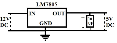
[image:4.612.210.408.143.217.2]D. Power Circuit Block Diagram
FIG: POWER CURCUIT BLOCK DIAGRAM
The above figure shows the block diagram of power circuit, the function of this circuit is to convert the 12 volt DC supply to 5 volt. The input side 12 volt DC supply is given and at the output side by using this circuit we get the 5 volt DC supply, the capacitor is used for avoiding fluctuations at the output side.
IV. PROPOSEDSYSTEM
Before applying the power we have to check whether the system is properly connected. If it is not then first we have to connect it properly. For the voice recognizer system we have to check whether both the Bluetooth modules are in range or not. If they are in range then we have to check that both the Bluetooth modules are bind properly with each other or not. If both the Bluetooth module are not bind or synchronized with each other than the system will not work so then we have to reset the Bluetooth modules so that the master Bluetooth will find the slave Bluetooth and get automatically synchronized with each other. Then we have to check that whether the voice is recorded or not in the voice module if not then first we have to train the voice module by the voice and set commands in proper manner if the accent while training the voice module does not match after then the system will not recognize the voice and the commands will not work. If there is lot of noise in near the mic then there will be problem while detecting the commands.
And for the upper dipper system we have to check whether the LDR is set in proper direction from where we have to take the light if not then we have to set the LDR in the proper direction and in the proper direction. If the light intensity does not match a specific range then the system will not work properly and if the distance between the LDR and the light is to large then also the system will not work in proper manner
As we all know that the voice controlling system is already in the vehicles. But we are working the project from which with the help of only the voice commands, the side indicators, pass light and the horn system can be controlled .And the second aim of our project is to make the upper dipper system automated.
[image:4.612.158.457.507.705.2]Technology (IJRASET)
FIG: Express PCB Step 2
The above figure shows the layout of the receiver circuit made by using express pcb.
The above figure is the print out of the receiver circuit made by using express pcb and after saving the layout this layout is been saved and printed on the white paper.
V. PERFORMANCESTUDIES
Technology (IJRASET)
FIG: Park Light Indication On
FIG: Automatic Dipper Mode
VI. CONCLUSION
As we have concentrate many methodologies of computerized watermarking innovation to secure visual information, so advanced watermarking innovation can give another approach to secure the copyright of mixed media data and to guarantee the sheltered utilization of sight and sound information. We are given the objective of advanced watermarking is to create an interactive media data that appears to be identical to a human eye yet at the same time permits its positive distinguishing proof in examination with the proprietors key if vital.
REFERENCES
[1] Janakiraman, Govindaswamy, Anita. International Journal for Research in Applied Science & Engineering Technology (IJRASET)Embeeded Automatic Vehicle Control System Using Voice Recognition On ARM 7 Processor April 2016.
[2] Pradeep L. Yadav , Sanjay.B Deshmukh Embedded Vehicle Control System based on Voice Processing using DSPIC. International Journal of Computer Applications (0975 – 8887) International Conference on Communication Technology 2013
[3] 1C. Jeeva, Anwar Naseer Khan, Junaid Azad Wani, Amit Kumar International Journal of Advanced Research in Computer Science and Software Engineering Volume 6, Issue 5, May 2016
[4] Usha Rani J et al | IJCSET(www.ijcset.net) | June 2015 | Vol 5, Issue 6,200-205
[5] Janakiraman., Govindaswamy., Anita. International Journal for Research in Applied Science & Engineering Technology (IJRASET) Issue IV, April 2016 [6] G.M. Pushpanjali, P.S. Mali, and R.R. Naman, International Journal on Emerging Technologies (Special Issue on ICRIET-2016) 7(2): 169-172(2016) [7] Udaya Sharma1, Deepak Rasaily , Tashi Rapden Wangchuk, Ankita Pradhan Kiratti Upashna International Journal of Engineering Trends and Technology
(IJETT) – Volume 33 Number 8- March 2016