OPTIMIZING COMMUNICATION AND COOLING COSTS IN HPC DATA CENTER
13
0
0
Full text
(2) Journal of Theoretical and Applied Information Technology 20th March 2016. Vol.85. No.2 © 2005 - 2016 JATIT & LLS. All rights reserved.. ISSN: 1992-8645. www.jatit.org. UCA 2.0. In 1996 the Europe technical community TC57 are join and began to work with IEC 61850 with a focus similar to that of UCA2.0, the UCA2.0 substation bus P2P message service called GOOSE was specified. In 1997 the UCA community and TC57 community agreed to work together to define the common international standard IEC 61850 specification , with this new specification the UCA2.0 GOOSE message was renamed UCA2.0 GSSE, and the enhanced GOOSE was specified to UCA2.0 GOOSE. IEC61850 P2P services are UCA2.0 GOOSE with enhanced functionality. We can look for IEC 61850 as much more than protocols application data and communication, logical nodes and data which are defined within (IEC 61850-7-4/-7-3), then we have the service interface , which is defined within (IEC61850-7-2), also a station bus defined within(IEC61850-8-1), and we also have the process bus defined within (IEC61850-9-2). We also have different layers, then we started with the modeling of information that represents our different functions and equipment in the substation, such as the circuit breaker, over current protection, distance protection etc. Next, we define the information model exchange, and then we also define the network stack layer that is used to share that information. Three protocols are used in station bus IEC 61850-8-1, TCP-IP Stack application layer, GOOSE/GSSE link layer protocol, and time sync SNTP (Simple Network Time Protocol). Also three protocols are used in the process bus (IEC 61850-9-1, IEC 61850-9-2), sample value protocol (link layer), GOOSE/GSSE (Link layer), and time sync (SNTP). The IEC 61850 protocol has the advantage of worldwide acceptability (internationally) for crossborder transmission of data within electrical installations. This protocol is characterized by special features, with its most important element being its data definition in the form of objects with a specific name and behavior. This allows for the interoperability between devices produced by different manufacturers [2]. In view of IEC 61850, protocol diversity and integration problems have been regarded as passé. on the time and costs of configuration, commissioning and maintenance can be reduced. The reduction of costs can be made possible with this protocol, and communication becomes more reliable, since one communication channel is used for all data in real time, synchronized through the Ethernet. Comprehending the principles, concepts, and methodologies of IEC 61850 is very easy, unlike other applied communication standards, such as IEC. E-ISSN: 1817-3195. 60870-5-101 /-103 /-104. By closing the gaps between substations and control center and between the process and bay level, the IEC 61850 standard seamless communication will overcome the last of the communication discontinuities; also we combine the MU and Breaker IED into one product for the optimized application of the process bus. Reference [1]; dwells into the IEC 61850 performance of the process bus through the Ethernet network. The possible uses of wireless technologies in power system operations were mentioned in reference [2].Reference [3] highlights some experimental measures and the related analysis implemented on real IEEE 802.11g/e networks. The implementation of the line differential protection using Wi-Fi was referenced in [4]. A thorough experimental study on the statistical characterization of the wireless channel in a variety of electricpower-system environments was further justified in reference [5]. Reference [6] analyses the real-time performance found to be achievable in the qualityof-service (QoS)-enabled 802.11 networks has been carried out. The understanding of the Wi-Fi technologies, the advantages that they can deliver and the research challenges of the smart grid was demonstrated in reference [7]. The RFI (Radio Frequency Interference) / EMI (Electromagnetic Interference) in substations has been under investigation for decades [8]-[17]. The RFI that results from the co-channel interference and EMI that arises from the spark plug ignition, switching transients in switchyards and inside control rooms are investigated in [9]-[13]. The Electric Power Research Institute (EPRI) in the US has done several experimental tests of the transient electromagnetic fields in the Air-Insulated Substation (AIS) and Gas-Insulated Substation (GIS). Based on the above observation, it is concluded that the EMI essentially has little impact to the communication in a WLAN based ISCS (Integrated Substation Control System). This is also confirmed by industrial experiences [18]. In addition, some noise reduction techniques have been proposed and studied to suppress the EMI [8]. For 802.11n, there is typically much less frequency interference in the 5GHZ band. The Smart Antenna settles the issue of interference from other radios that have circular polarization. Based on the literature review, there is an assumption that substation RFI/EMI in the 802.11 frequency band (2.4 and 5 GHz) is small and therefore, its impact can be tolerated. No literature has been found to examine the performance of IEEE 802.11n WLANs for the time-. 240.
(3) Journal of Theoretical and Applied Information Technology 20th March 2016. Vol.85. No.2 © 2005 - 2016 JATIT & LLS. All rights reserved.. ISSN: 1992-8645. www.jatit.org. delay requirement criteria specified in IEC 61850-5, and the influence of noise on WLAN performance in substation, also no survey works on the real time critical application in the substation, like protection using WLAN. This paper describes the performance evaluation of communication in substations under different scenarios. The Merging Unit (MU), a very important component of IEC 61850 standard, captures continuously streamed data from the process bus, thus it is a reservoir of large data. Getting the Sampled Value (SV) message from the WLAN Merging Unit (MU) incurs some form of delay. Besides, point-to-multi-point (P2MP) is another important communications in substation automation. The information related to real-time pricing, commands for fault isolation or energy flow redirection, instructions for demand-response Functionalities, etc., furthermore point to point (P2P) communications between two devices could be exploited to meet security, scalability, and hard real-time requirements. Thus, also this paper focuses on the performance of SV ETE Delay using the Multipoint-To-Point using AP (Access Point) network, also it looks into the performance of SV while the number of IEDs increases, in the process bus, and finally it dwells into the influence of the Electro-Magnetic Interference (EMI), and Radio Frequency Interference (RFI) on the ETE delay and throughput performance in WLAN. 2. SALIENT FEATURES OF IEC 61850 A. Main message types and transmission time According to IEC 61850-5, messages are classified into seven categories. Type 1: The fast messages are used to relocate the messages that require quick response, e.g. “Trip”, “Close”, “Reclose order”, “Start”, “Stop”, “Block", "Unblock”, “Trigger”, “Release”, “State change”. Type 2: Medium speed messages are used to shift information about status and measurement in nonfault situation such as an r.m.s. The message is likely to contain a time-tag that is set by sender. In this case transmission time is not much critical. Type 3: Low speed messages are utilized for low speed control functions. It transfers transmission of event records, changing set-point values and general presentation of data. Type 4: Raw data messages help transfer output data from transducers and digital transformers.. E-ISSN: 1817-3195. Type 5: File transfer function causes a transfer of large files of data for the purpose of recording, and settings. Data is split into blocks of limited length and it in turn allows other communication network activities. In this case, transmission time is not critical and has no certain limits. Type 6: Time synchronization messages help synchronizes internal clocks of IED in the SAS. Depending on a specific purpose, such as time tagging or sampling precision of data, distinct classes of time synchronizing precision are needed. Type 7: Command messages that have access control are used to reassign control orders issued from local/remote HMI functions. In this case, a high level of security is essential. All message categories and analogous transmission time requirements are contained in Table 1. B. Communication Stack The described 07 types of messages are mapped into different communication stacks based on their performance parameters. Figure 1 show that the raw data samples (type 4) and Generic Object Oriented Substation Event (GOOSE) messages (type1, 1A) are time critical and therefore are directly mapped with low level Ethernet layer. This gives an advantage of improved performance for real time messages by shortening the Ethernet frame (with no upper layer protocol overhead) and reducing processing time. In medium speed message (type 2), the command message is given an access control (type 7) and in case of low speed message (type 3), the file transfer function (type 5) is mapped with Manufacturing Message Specification (MMS) protocol suit which contains a TCP/IP stack above the Ethernet layer. The time synchronization messages (type 6) are broadcasted to all IEDs in a substation using UDP/IP. The Generic Substation Status Event (GSSE) message is not modeled in accordance with IEC 61850 due to its certain modeling complexity and its minor affect to the overall network performance. Moreover, an identical profile can be used because they have similar AProfile and T-Profile. The above messages flow in a substation is performed through following methods: polling, publishing, log or report. For instance, raw data samples are published from MU IED to P&C IEDs. GOOSE messages are published between P&CIEDs and breaker IEDs. Meter values or breaker status maybe updated by polling or reporting.. 241.
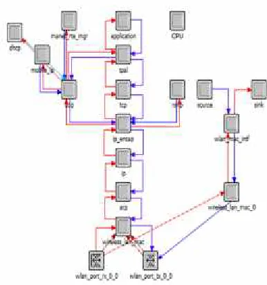
(4) Journal of Theoretical and Applied Information Technology 20th March 2016. Vol.85. No.2 © 2005 - 2016 JATIT & LLS. All rights reserved.. ISSN: 1992-8645. www.jatit.org. Figure 1: Message Communication Stack in IEC 61850 .. 3. IED MODELS FOR SASs The physical electrical devices of the Distribution Energy Resource (DER) system and substations have corresponding communication devices connected to them. These physical communication devices are the Intelligent Electronic Devices (IEDs). Three types of IEDs should be modeled in every DER plant or substation: Merging Unit (MU), Intelligent Circuit Breaker (ICB), and the Protection and Control Unit (P&C). The IEDs of the DER system are modeled in OPNET based on the type of the traffic generated or received by them. In the OPNET modeler software, the object palette under wireless_lan_advanced type library contains two types of node models. The ‘wlan_station_adv’ node corresponds to two layer nodes, which send the data that are directly mapped on the MAC layer. In the ‘wlan_workstation_adv’ the node data is mapped on the MAC layer through TCP/IP layers. Hence, in order to simulate these IEDs a custom node model is designed, leaning on the object oriented modeling approach, in OPNET Modeler using both the node model and process model editor. To confirm the performance of the process bus, the MU IED seeks to combine the three phase current and voltage and then transmit the raw data sampled values to the LAN network following the description found in the IEC 61850-5, for the network Performance simulation purpose. The raw data sample rate can undergo changes, based on IEC 61850; hence the minimum sampling rate for protection is 400 Hz. The functionalities of ICB rest in receiving the trip message, and sending a multicast GOOSE/GSSE event (the status of the circuit breaker) to the protection IEDs. In a similar manner, as the MU IED, a user can make a. E-ISSN: 1817-3195. configuration of the event packet size, address and transmission type (P2P, multicast, broadcast). The P&C IED could be configured to two varying modes, which are the normal load mode and the fault mode. It produces the constant rate status packets and delivers them to the PC station in the normal mode, while generating the variable rate status packets and multicasting the trip GOOSE message to the corresponding breaker IEDs in the fault mode. In order for it to work well, the user also only needs to configure its address, multicast group address, destination address and other parameters according to the simulation requirements established. The communication protocol stacks in MU, ICB and P&C are comparatively speaking, simple towards achieving the real-time communications, which only include 3 layers: application layer, link layer and physical layer. It can be simply achieved by using the model of WLAN_station_adv in OPNET module as shown in Figure 2. Figure 3 shows the customized node models for wireless Intelligent Circuit Breaker (ICB), and the protection and control intelligent electronic device unit (P&C) IED developed in the OPNET node model editor, which supports GOOSE, Sample Values and MMS type of traffic. The Merging Unit IED only sends Sample values to other IEDs, in which data is directly mapped on to the MAC layer.. Figure 2: WLAN_station_adv Model in OPENT Modeler. As shown in Fig.2, the raw data source module (bursty_gen) enables the user to define the packet format, packet size, and the packet rate the user seeks to generate (configure the sample rate, start time, stop time, packet size, and address in model.). First of all, the sink module will calculate the packet transferring time, gather other statistical data for all the packets coming from the network and then destroying them so that there is more room in the. 242.
(5) Journal of Theoretical and Applied Information Technology 20th March 2016. Vol.85. No.2 © 2005 - 2016 JATIT & LLS. All rights reserved.. ISSN: 1992-8645. www.jatit.org. memory space. The WLAN_mac_intf, defer and mac modules implement the WLAN protocols and algorithms. This is the place where OPNET processes both the incoming and outgoing packets. The WLAN_port_rx0 and WLAN_port_tx0 are OPNET symbol radio receiver and transmitter respectively.. E-ISSN: 1817-3195. created to satisfy the traffic pattern in substation communication networks. We have merged, in this paper, the MU and ICB in a single device. Other parameters like the frequency band, modulation type, and transmitter power can also be chosen during simulation. The distances between nodes to calculate the link effects such as propagation delay, interference, and received power levels were analyzed during simulation. After completing the network configuration, the statistics to be gathered shall be decided. For the network performance research, the End to End (ETE) delay for time critical messages is a vital statistic that mirrors the network performance. Having filled in the duration, we simply click the RUN button and OPNET will simulate the network and collate the statistics. The actual simulation time will have to rely on the computer speed. After completing the simulation, the results could be viewed graphically on the Project Editor. OPNET could also gather all the results to produce a web report. The result analysis compares the simulation results under varying configurations. LINE. 110 Kv. Transformer. Figure 3: Customized Node Model for Wireless Breaker and Protection & control IEDs. 14.2 Kv. Breaker CT4 Feeder 4. Breaker CT3 Feeder 3. Breaker CT2 Feeder 2. CT1 Feeder 1. Having modeled WLAN IED models successfully, the Substation Automation System (SAS) network research platform could now be built upon. A device palette, containing all the SAS network device models, is created on Project Editor serving to construct and edit the topology of a communication network model. The device palette permits the user to drag any WLAN device to the project workspace and to build various WLAN communication networks. The network configuration involves the data flow analysis of the SAS network, the set-up of the network traffic and network parameter configuration. For example, the raw data sampling rate, packet size, start time and stop time have to be chosen for each MU IED prior to the simulation. Moreover, for those messages to be able to be transmitted to right receivers, the source address, destination address, multicast group address and transmission method should be made specific for each IED. To define the traffic passing through the Manufacturing Message Specification (MMS) stack, Station PC, P&C IED and breaker IED profiles are. Breaker. 4. SIMULATION OF SASs NETWORK. Figure 4: Substation Single Line Diagram. 5.. SAMPLE SUBSTATION AUTOMATION SYSTEM CONSTRUCTION AND PERFORMANCE EVALUATION. IEC 61850 gives support to the substation automation and the standardized communication technique in both station bus and process bus. We have come up with different scenarios as well as techniques to develop the Merging Unit in WLANthis is one of the important data acquisition equipment in the process bus, under the IEC 61850 communication protocol.. 243.
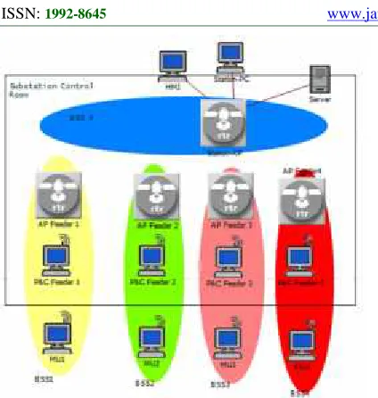
(6) Journal of Theoretical and Applied Information Technology 20th March 2016. Vol.85. No.2 © 2005 - 2016 JATIT & LLS. All rights reserved.. ISSN: 1992-8645. www.jatit.org. E-ISSN: 1817-3195. speed of 65Mb/s base and 600 Mb/s maximum . From the results, we note that this network architecture has satisfied the substation message performance requirement which is 4 ms for protection. Simulation of above scenario can be seen in figure 5. There are five access points, four for each protection function, and one for the station level communication. Moreover, the four bay level access points have two wireless interfaces to communicate with first, the protection devices within the basic service set and second, with the wireless backbone of station bus BSS 5. Other station level devices, such as Station PC, HMI, and Server, are connected to substation backbone (BSS 5).The other parameter setting for this scenario are shown in table-3.. Figure 5: Wireless Communication Feeder Protection Network For 110/14.2 Kv Distribution Substation Simulated In OPNET. The MU is an interface unit that receives a multitude of analog inputs such as CT (current Transformer)/PT (potential transformer) and digital signals and produces multiple time-synchronized serial unidirectional multi drop digital point-to-point outputs. For the 61850 communication, the MU must have an appropriate structure for IEC 600447,-8 and IEC 61850-9-2. The MU transfers the data using the IEC 61850-9-2 protocol after it synchronizes the signals measured from the sensors installed in the electric power system with the GPS. The MU specification must support different transmit samples which are equal to 480 messages/sec minimum, and different sample rates equal to 8 samples in minimum, and work under 50Hz/60Hz System frequency, and with a number of channels. The MU consists of the sensor interface, signal processing and communication part. Then, the MU design for WLAN must be considered in more detail. In this paper, the 110 Kv / 14.2 Kv substation transformer bays, and 4 feeder bays are selected as an example of application with different scenarios for MU. Fig. 4 highlights the single line diagram and physical bays of the substation. In Table 2 scenario, each feeder bay is modeled into BSS (infrastructure Basic Service Set) which has one MU and breaker IED, one P&C IEDs. Each packet for the MU contains one ASDU, the packet size is 128 bytes, and the packet generations inter arrival time is variable as shown in table 2. From table 2, we are shown the general comparisons of IEEE 802.11n WLAN frequency band simulation results under a range of raw data sampling rates and the WLAN 244.
(7) Journal of Theoretical and Applied Information Technology 20th March 2016. Vol.85. No.2 © 2005 - 2016 JATIT & LLS. All rights reserved.. ISSN: 1992-8645. www.jatit.org. E-ISSN: 1817-3195. Table 1: Message Type and Performance Requirement in SAS Network [19] IEC61850 Message. Implementation Smart. Allowed Message Delay. Type. Grid Application. at Distribution[sec]. GOOSE/GSE (type 1). Control Commands to. User Priority Levels. Publisher/Subscriber Message 0.003 - 0.01. 7. 0.01. 6. trip ,block, and so on; state change Sample values(type 4). Protection function ;&metering. Client/Server Messages Medium speed. Voltage Control. 0.05 - 0.1. 4. Condition Monitoring. 0.1 - 5. 2. Data recording;. 1–5. 0. message(type 2) Low speed message(type 3) File transfer (type 5). event/alarm list; setting. Table 2: Raw Data and Trip Message ETE Delays for Feeder protection. IEEE 802.11n. Sampling Rate. Max. Raw Data. Max. Raw Data. 65Mbps(base) / 600. (Sample/s). Message. Message. Delay. Delay. Delay. Delay. (No Priority Tagging). (Priority Tagging). (No Priority. (Priority Tagging). (ms). (ms). Tagging). (ms). Mbps (max). Max. Trip Message. Max. Trip Message. (ms). 2.4 GHz (HT). 5.0 GHz (HT). 400. 1.2. 1.0. 1.3. 0.9. 800. 0.8. 0.55. 1.2. 0.8. 1600. 1.2. 0.65. 1.8. 1.2. 4000. 1.5. 1.1. 2.2. 1.6. 400. 0.88. 0.7. 0.99. 0.5. 800. 0.6. 0.4. 1.0. 0.45. 1600. 0.75. 0.41. 1.2. 0.5. 4000. 1.2. 0.75. 1.6. 0.65. 245.
(8) Journal of Theoretical and Applied Information Technology 20th March 2016. Vol.85. No.2 © 2005 - 2016 JATIT & LLS. All rights reserved.. www.jatit.org. Table 3: Attribute of wlan_station_adv Node. bytes, and the P&C IED packet length is equal to 84 bytes. From table 5, we observe that IEEE 802.11n at 5GHz satisfies the ETE delay requirement at two different sampling frequencies, while at 2.4 GHz the ETE delay does not satisfy the substation requirement at 1600Hz sampling frequency. Figure 7 shows this above scenario implemented by opnet software, from this figure we can observe that four feeder can be protected by single P&C IED feeder bay.. Wlan_station_adv Constant(0.000001) Constant(0.004) Variable t Constant(128) Access categories AC(1) PHY CWmin PHY CWmax 3. CT 2. MU4. MU4. MU3. Feeder 3. MU1. Brea ker 1 CT 1 Feeder 1. In Table 4 Scenario, Each transformer bay is modeled into different BSSs, i.e. BSS6 which contain two MUs and breaker IED, one P&C IED for differential transformer protection, the packet size in each MU is equal to 128 bytes, and 84 bytes for P&C IED, while other attributes are shown in table 4. It can be observed that this scenario satisfies the substation protection of the ETE delay requirement. Simulation of this scenario using Opnet software can be seen in figure 6.. Breaker 2. Variable t: depends on sampling frequency.. Access Point. CT 3. Breaker 3. 1 Short (400 ns) Disable Disable. CT 4. Brea ker 4. Access categories AC(3) (PHY CWmin +1) / 4 - 1 (PHY CWmin +1) / 2 - 1 2. Feeder 2. Model Start time(seconds) On state time(seconds) Interarrival time(seconds) Packet size(bytes) EDCA Parameter no priority CWmin CWmax AIFSN EDCA Parameter priority CWmin CWmax AIFSN HighThroughput Parameter Number of Spatial Stream Guard Interval 40 MHz operation Status Green Field Operation. E-ISSN: 1817-3195. .11n 802 E E IE. mm s Co eles r i W. at unic. ion. Link. Feeder 1. ISSN: 1992-8645. Substation Control Room. P&C IED Feeder Bay. BSS 6 CT. Figure 7: Economic Feeder Protection Breaker. MU1. Secondly, for the economic differential transformer protection, we used a single MU that has two ASDUs, each ASDU that is linked with a specific current transformer (CT), and single P&C IED, and the result for this scenario is illustrated in table 6. As can be seen in table 6 the ETE delay at all sampling frequency has been able to meet the protection requirement stated in IEC 61850-5.the simulation of the above scenario can be seen in figure 8 using opnet software. Where, the figures marked with * do not satisfy the time delay communication requirement given in IEC 61850-5 which must be less than 4ms.. 14.2 Kv. P&C IED. Transformer. 110 Kv. AP. Breaker. CT MU2. Figure 6: Transformer Differential Protection. After that, we consider the economic scenario for the feeder and differential transformer protection. First off all, for the feeder protection we assume that four MUs are connected to a single P&C IED in specific BSS, each MU has a packet length of 128 246.
(9) Journal of Theoretical and Applied Information Technology 20th March 2016. Vol.85. No.2 © 2005 - 2016 JATIT & LLS. All rights reserved.. ISSN: 1992-8645. www.jatit.org. E-ISSN: 1817-3195. CT. AD C2 AD C3 AD C6 AD C7. Sensing Unit. AD C8. Feeder 1. CH8. WLAN I EE E 802. 11 a /g/n Communica tion U nit. CT 2. AD C4. CH5. Sig nal Condit ion Circuit s. CH3. IRIG-B-TIME SYNC FUNCTION. AD C5. CT 4. IRIG-B-SIGNAL CH2. CH6. Feeder 3. Breaker. Access Point GPS. CH7. Feeder 2. P&C IED. CH1. CH4. CT 1. MU. Feeder 1. 14.2 Kv. Breaker 1. Transformer. Break er 2. 110 Kv. CT 3. B reaker 3. I Co EEE mm 80 u 2 .1 Li n n ica 1n k t io n. Breaker. Breaker 4. AP. AD C1. MU HARDWARE COMPONENTS. CT. Substation Control Room. P&C IED Feeder Bay. Digital Signal Processing Unit. Figure 9: Four Feeder Protection Using Combined MU.. Figure 8: Economic Transformer Differential Protection. Finally, we looked into the four feeder protection by using a single combined MU. Each Application Protocol Data Unit (APDU) generated by feeders MU IED has four Application Service Data Units (ASDUs), because it contains four datasets with reading from specified CT. Also using single P&C IED, the combined MU IED is combined data from four feeders and then sending raw data message (type 4) to the corresponding P&C IED at a specified sampling rate when the simulation begins. The packets length for the combined MU is 320 bytes. This is regards to 64 bytes for each four ASDUs, and 64 bytes for header packet. From table 7, we observe that the ETE delay at all sampling frequency satisfies the substation automation protection requirement, which is less than 4ms. Note that the Raw data message is the message from MU to P&C IED, while the trip message is the message from P&C IED to corresponding breaker which is already combined with MU. The above scenario simulation using opnet software can be seen in figure 9.. From figure 9, we can observe that MU consists from data acquisition unit, digital signal processing unit, and communication unit. The Opnet modeler provides a suitable environment to study the effect of the interference noise, and electromagnetic noise available in the SAS. The radio link between the transmitter device and receiver device was modeled in the number of pipeline stages according to the opnet software modeler. Six stages were associated with transmitter, and eight stages with the receiver. Stage 8 which represents the background noise, can study the effects of all background noise sources including the RFI (Radio Frequency Interference) from neighboring devices, and the EMI (Electromagnetic Interference) available in bands. The site surveys must be done before the implementation, including scanning the two frequency bands 2.4GHz, and 5.0 GHz which is used in IEEE 802.11n. The measured noise is added to the default background noise. The transmitted power of the transmitter, antenna gain, receiver sensitivity, and receiver antenna gain is a very important parameter, which is used to control the effect of noise. Whatever the form of noise measuring the background power noise including the EMI, RFI, it must be less than the power sensitivity of receiver which is equal to -95dBm in this exercise, and otherwise the degradation in the performance of the WLAN node becomes too high. Then the designer needs to recommend the following to ensure that the Performance and. 247.
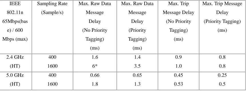
(10) Journal of Theoretical and Applied Information Technology 20th March 2016. Vol.85. No.2 © 2005 - 2016 JATIT & LLS. All rights reserved.. ISSN: 1992-8645. www.jatit.org. Capacity Requirements are achieved for using the WLAN in the SASs. The frequency plan is a key component for any network and the exercise is to evaluate the number of nodes or clients on the basis of coverage and capacity. The plan can then allocate suitable channels for the best performance of the network minimizing the co-channel and adjacent channel interference. At least, 5.0 GHz unlicensed spectrum has less impact by the RFI/EMI noise compared. E-ISSN: 1817-3195. with 2.4GHz. This is to make sure that the above design channels/band is free of interferences. Further Enhancements or Expansions in Capacity in the WLAN Network (data rate can be increased) by one of the following: configuring more than one spatial stream (MIMO), enabling short Guard Interval (GI) Capability, and enabling the support for 40MHz operation. This is all supported in IEEE 802.11n.. Table 4: ETE Delay Transformer Differential Protection. IEEE. Sampling Rate. Max. Raw Data. Max. Raw Data. Max. Trip. Max. Trip Message. 802.11n. (Sample/s). Message. Message. Message Delay. Delay. 65Mbps. Delay. Delay. (No Priority. (Priority Tagging). (base) / 600. (No Priority. (Priority. Tagging). (ms). Mbps (max). Tagging). Tagging). (ms). (ms). (ms). 2.4 GHz. 400. 1.5. 1.1. 1.5. 1.0. (HT). 800. 1.6. 1.3. 2.5. 1.2. 1600. 2.6. 1.8. 5.0. 3.0. 5.0 GHz. 400. 0.9. 0.75. 1.3. 0.7. (HT). 800. 1.3. 0.9. 1.2. 0.8. 1600. 1.6. 1.1. 2.0. 1.0. Table 5: Economic Scenario ETE Delay Feeder’s Protection. IEEE. Sampling Rate. Max. Raw Data. Max. Raw Data. Max. Trip. Max. Trip Message. 802.11n. (Sample/s). Message. Message. Message Delay. Delay. 65Mbps(bas. Delay. Delay. (No Priority. (Priority Tagging). e) / 600. (No Priority. (Priority. Tagging). (ms). Mbps (max). Tagging). Tagging). (ms). (ms). (ms). 2.4 GHz. 400. 1.6. 1.4. 0.9. 0.8. (HT). 1600. 6*. 3.5. 1.0. 0.8. 5.0 GHz. 400. 0.66. 0.65. 0.45. 0.25. (HT). 1600. 1.8. 1.3. 0.53. 0.5. 248.
(11) Journal of Theoretical and Applied Information Technology 20th March 2016. Vol.85. No.2 © 2005 - 2016 JATIT & LLS. All rights reserved.. ISSN: 1992-8645. www.jatit.org. E-ISSN: 1817-3195. Table 6: Economic Scenario ETE Delay Differential Transformer Protection. IEEE. Sampling Rate. Max. Raw Data. Max. Raw Data. Max. Trip. Max. Trip Message. 802.11n. (Sample/s). Message. Message. Message Delay. Delay. 65Mbps. Delay. Delay. (No Priority. (Priority Tagging). (base) / 600. (No Priority. (Priority. Tagging). (ms). Mbps (max). Tagging). Tagging). (ms). (ms). (ms). 400. 1.3. 1.2. 1.4. 1.1. 2.4 GHz. 800. 1.0. 0.7. 1.3. 1.0. (HT). 1600. 1.1. 0.8. 1.8. 1.5. 4000. 2.4. 2.2. 2.0. 1.8. 400. 0.9. 0.65. 1.0. 0.7. 5.0 GHz. 800. 0.8. 0.4. 1.1. 0.6. (HT). 1600. 0.75. 0.35. 1.3. 0.8. 4000. 1.4. 1.1. 2.6. 2.0. Table 7: Economic Scenario ETE Delay Feeders’ Protection. IEEE 802.11n. Sampling Rate. Max. Raw Data. Max. Raw Data. Max. Trip. Max. Trip Message. 65Mbps(base). (Sample/s). Message. Message. Message Delay. Delay. / 600 Mbps. Delay. Delay. (No Priority. (Priority Tagging). (max). (No Priority. (Priority. Tagging). (ms). Tagging). Tagging). (ms). (ms). (ms). 400. 1.2. 0.9. 1.0. 0.9. 800. 0.93. 0.55. 1.5. 1.2. 1600. 1.5. 1.0. 2.0. 1.8. 4000. 2.8. 2.7. 3.3. 3.1. 400. 0.9. 0.6. 1.0. 0.8. 800. 0.7. 0.35. 1.1. 0.65. 1600. 0.8. 0.4. 1.5. 1.1. 4000. 2.4. 1.8. 3.0. 3.0. 2.4 GHz (HT). 5.0 GHz (HT). 6. CONCLUSION The wireless technology has demonstrated significant growth over the recent years and has become more and more mature. In this paper, we discussed many topics to the success of WLAN in the substation automation and protection in terms of the cost and flexibility.. The use of WLAN MU IED, P&C IED, and Breaker IED models to build Independent Basic Service Set (IBSS), or the Basic Service Set (BSS) network in SAS to simulate the network performance has been shown to be an effective tool for solving critical performance problems. Through the simulations of the sample application, it could be observed that the IEC61850 substation. 249.
(12) Journal of Theoretical and Applied Information Technology 20th March 2016. Vol.85. No.2 © 2005 - 2016 JATIT & LLS. All rights reserved.. ISSN: 1992-8645. www.jatit.org. communication system based on WLAN has shown sufficient performance to satisfy the time critical messages in the substation automation system. However, the IEDs and Access Point (AP) with the ability to provide priority tagging shall be used for the networks with heavy traffic. In real substation automation systems, it is beneficial for the protection and communication engineers to evaluate the message delay inside the network so that the network performance specified in IEC 61850 could be achieved by selecting proper Scenario topology and network configurations. Then the question is that? Does wireless communication meet the requirements of IEC 61850 Protocol, the answer it all depends on the application requirements and the traffic load. The analysis of the survey shows that the distribution of RFI / EMl in 802.11 frequency bands is small and the impact can be tolerant. Heavy fading may exist in the Integrated Substation Control System (ISCS) environment, but one can adjust the placements of APs and antennas to avoid it. The key drivers for a WLAN-based communication in the ISCS are really the installation / re configuration simplicity and substantial savings gained which will justify the investment in wireless equipment like the APs. Finally, if we combine all protection functions into a single device i.e. the MU, ICB, and P&C IED, By combining all protection functions, we were able to lower the number of mission-critical components by eliminating an AP and the time synchronization source (at least for simple, single-ended functions such as overcurrent or distance). The resulting protection system becomes very high reliability. But the big problem it does not work in cases of distributed protection functions such as bus or line differential protection. REFERENCES: [1]. David M. E. Ingram, Pascal Schaub, Richard R., and Duncan A. Campbell, “Performance Analysis of IEC 61850 Sampled Value Process Bus Networks,” IEEE Trans. Ind. Informat.,vol. 9,no. 3, pp.1445-1454, Aug. 2013. [2] F.Cleveland, “Use of Wireless Data Communication in Power System Operations,” EPRI Report 1011751, Mar. 2006. [3] GianlucaCena, Ivan CibrarioBertolotti, Adriano Valenzano, and Claudio Zunino,” Evaluation of Response Times in Industrial WLANs,” IEEE Trans. Ind. Informat., vol. 3, no. 3, pp.191-201, Aug. 2007. E-ISSN: 1817-3195. [4] K. M. Abdel-Latif, M. M. Eissa, A. S. Ali, O. P. Malik, and M. E. Masoud,” Laboratory Investigation of Using Wi-Fi Protocol for Transmission Line Differential Protection,” IEEE Trans. Power Del., vol. 24, no. 3, pp. 1087–1094, Jul. 2009. [5] Vehbi C. Gungor, Bin Lu, and Gerhard P. Hancke,” Opportunities and Challenges of Wireless Sensor Networks in Smart Grid,” IEEE Trans. Ind. Electron.,” vol. 57, no. 10, pp. 3557-3564, Oct. 2010 [6] GianlucaCena, Lucia Seno, Adriano Valenzano, and Claudio Zunino,” On the Performance of IEEE 802.11e Wireless Infrastructures for SoftReal-Time Industrial Applications,” IEEE Trans. Ind. Informat., vol. 6, no. 3, pp.425-437, Aug. 2010 [7] Vehbi C. Güngör, Dilan Sahin, TaskinKocak, SalihErgüt, ConcettinaBuccella, Carlo Cecati, andGerhard P. Hancke, “Smart Grid Technologies: Communication Technologies and Standards,” IEEE Trans. Ind. Informat., vol. 7, no. 4, pp. 529-538, Nov. 2011 [8] Zen-Ichiro Kawasaki and Osamu Fujiwara, ed.,Commission E: Electromagnetic Noise and Interference, Nov. 1995 - Oct. 1998. [9] C. M. Wiggins and S.E. Wright, “Switching transient fields in substations,” IEEE Trans. Power Del., vol. 6, no. 2, pp.591-600, 1991. [10] C. M. Wiggins and S. E. Wright, “Transient Electromagnetic Interference in Substations,” IEEE Trans. Power Del., Vol. 9, no.4, pp. 18691884, 1994. [11] Q. Q. Li and Y. M. Li, “The Transient Electromagnetic Fields Caused by the Operation of Disconnector in Substation and Protection,” High Voltage Engineering, vol. 27, no. 4, pp.65-67, 2001. [12] C. M. Wiggins et al, “Measurement of switching transients in 115 kV substation,” IEEE Trans. Power Del., vol. 3, no.1, pp.756769, 1989. [13] R. Malewski et al, “Measurement of switching transients in 735 kV substations and assessment of their severity for transformer insulation,” IEEE Trans. Power Del., vol. 3, no.4, pp.13801390, 1988. [14] Intersil Corporation, ed., Effects of Microwave Interference on IEEE 802.11 WLAN Reliability, May. 1998. [15] J. Geier, “Minimizing 802.11 interference Issues,” http://www.80211-planet.com, Jan. 2002.. 250.
(13) Journal of Theoretical and Applied Information Technology 20th March 2016. Vol.85. No.2 © 2005 - 2016 JATIT & LLS. All rights reserved.. ISSN: 1992-8645. www.jatit.org. [16] Ming-JuHo, Michael S. Rawles, Marcel Vrijkorte and Louis Fei, “RF Challenges for 2.4 and 5 GHz WLAN Deployment and Design, “Atlanta Conf. on Wireless Communication and Networking, vol. 2,pp.783-788,2002. [17] S. Selby and A. Amini et al, “Simulating Interference Issues between Bluetooth PANS and 802.11b and 802.11g WLANs,” Innovative Wireless Technologies IWT (http://www.iwtwireless.com), Agilent Technologies (http://www.aqilent.com), 2001. [18] T. Brunsvik and S. Kjesbu,ABB Corporate Research, ed., Radio wave Propagation in Industrial Environment, Feb. 2000. [19] Nasser Hasan Ali, BorhanuddinMohd. Ali, Mohammed A. Abdala, Mohammad Lutfi Othman, Fazirulhisyam b. Hashim, “Comparisons process-to-bay level peer-topeer network delay in IEC 61850 substation communication systems, “Journal of Electrical Systems and Information Technology, vol. 1, no. 3, pp. 266–275, Dec. 2014.. 251. E-ISSN: 1817-3195.
(14)
Figure

![Table 1: Message Type and Performance Requirement in SAS Network [19]](https://thumb-us.123doks.com/thumbv2/123dok_us/8909186.958380/7.612.83.514.105.324/table-message-type-performance-requirement-sas-network.webp)
+5


Related documents
1. To study the customer satisfaction of selected society. To know the dealers are satisfied with the services provided by the society. To Give Suggestion For the best performance
4-RUU is an over-constrained PM,it has beenproventhat 4-RUU mechanism has three operation modes with Study's kinematic mapping of the Euclidean group se(3) dual quaternion
Lesson 1: Opening Microsoft Project Schedule from Clarity Lesson 2: Opening Microsoft Project Schedule from MSP Exercises – Hands-on practices and Learning Confirmation Quiz.
Therefore, the result of this query is that the database changes the password of the administrator (―admin‖) to an attacker specified value. These types of injections
The novel findings of our study on severe sepsis patients are that reduced MMP-9/TIMP-1 ratio and increased MMP-10 lev- els may be of great pathophysiologic significance in terms
In figure 2 both the methods are combined by encrypting message using cryptography and then hiding the encrypted message using steganography. The resulting stego-image can
CI = cardiac index; Con Int = confidence interval; CPI = cardiac power index; CVP = central venous blood pressure; HP = hourly portion; MAP = mean arterial blood pressure; MPAP =
movement for liberation and radical social change manifested in much community arts and. community music practice over
