CP/M-86®
Operating System
CP/M-86™
Operating System
System Guide
Copyright ~ 1981
Digital Research P.O. Box 579 801 Lighthouse Avenue Pacific Grove, CA 93950
(408) 649-3896 TWX 910 360 5001
COPYRIGHT
Copyright ~ 1981 by Digital Research. All rights reserved. No part of this publication may be reproduced, transmitted, transcribed, stored in a retrieval system, or translated into any language or computer language, in any form or by any means, electronic, mechanical, magnetic, optical, chemical, manual or otherwise, without the pr ior wr i tten permission of Digital Research, Post Office Box 579, Pacific Grove, California, 93950.
DISCLAIMER
Dig i tal Research makes no representations or warranties with respect to the contents hereof and specifically disclaims any implied warrantlies of merchantabi1i ty or fitness for any particular purpose. Further, Digital Research reserves the right to revise this publication and to make changes from time to time in the content hereof without obligation of Digital Research to notify any person of such revision or changes.
TRADEMARKS
CP/M, CP/M-86, and CP/NET are registered trademarks of Digital Research. ASM-86, CP/M-80, DDT-86, LINK-80, MP/M, MP/M-86, and TEX are trademarks of Digital Research. Intel is a registered trademark of Intel Corporation.
Foreword
The CP M-86 0 eratin S stem S stem Guide presents the system programming aspects of CP M-86 , a s1ngle-user operating system for the Intel@ 8086 and 8088 l6-bit microprocessors. The discussion assumes that you are familiar with CP/M®, the Digital Research 8-.bit operating system. To clarify specific differences with CP/M-86,
this document refers to the 8-bit version of CP/M as CP/M-80T .M .•
Elements common to both systems are simply called CP/M features.
This System Guide presents· an overview of the CP/M-86 programming inter face conventions. It also descr ibes procedures for adapting CP/M-86 to a custom hardware environment.
Table of Contents
I CP/M-86 System OVerview
1.1 CP/M-86 General Characteristics • 1.2 CP/M-80 and CP/M-86 Differences.
2 Command Setup and Execution Under CP/M-86
2.1 CCP Built-in and Transient Commands
2.2 Transient Proqram Execution Models
2.3 The 8080 Memory Model 2.4 The Small Memory Model 2.5 The Compact Memory Model
2.6 Base Page Initialization
2.7 Transient Program Load and
3 Command (CMD) File Generation
3.1 3.2 3.3 3.4
Intel Hex File Format • Operation of GENCMD • • • • Operation of LMCMD
Command (CMD) File Format
.
.
Exit.
· .
·
.
·
4 Basic Disk Operating System (BDOS) Functions
.
4.1 4.2 4.3 4.4
BDOS Parameters and Function Codes • • • .
Simple BDOS Calls • • • • • •
BDOS File Operations . • • • • • • • • BDOS Memory Manaqement and Load
5 Basic I/O System (BIOS) Organization
5.1 5.2 5.3 5.4
Organization of the BIOS • • • • • The BIOS Jump Vector
Simple Peripheral Devices BIOS Subroutine Entry Points
6 BIOS Disk Definition Tables
6.1 Disk Parameter Table Format • • • • • .
6.2 Table Generation Using GENDEF •
6.3 GENDEF Output • • • • • • . •
7 CP/M-86 Bootstrap and Adaptation Procedures
7.1 The Cold Start Load O~eration
7.2 Organization of CPM.SYS
Appendixes
A Blocking and Deblocking Algorithms
B Random Access Sample Program • • • • •
C Listing of the Boot Rom • • • • • • • • • • •
D LDBIOS Listing • • • • • • • • • •
E 'BIOS Listing
F CBIOS Listing • •
87
95
103
113
121
Section 1
CP /M-86 System Overview
1.1 CP/M-86 General Characteristics
CP/M-86 contains all facilities of CP/M-80 with additional features to account for increased processor address space of up to a megabyte (1,048,576) of main memory. Further, CP/M-86 maintains file compatibility with all previous versions of CP/M. The file structure of version 2 of CP/M is used, allowing as many as sixteen drives with up to eight megabytes on each drive. Thus, CP/M-80 and CP/M-86 systems may exchange files without modifying the file format.
CP /M-86 resides in the file CPM. SYS, which is loaded into memory by a cold start loader during system initialization. The cold start loader resides on the first two tracks of the system disk. CPM.SYS contains three program modules: the Console Command Processor (CCP), the Basic Disk Operating System (BDOS), and the user-conf igurable Basic I/O System (BIOS). The CCP and BDOS portions occupy approximately 10K bytes, while the size of the BIOS varies with the implementation. The operating system executes in any portion of memory above the reserved interrupt locations, while the remainder of the address space is partitioned into as many as eight non-contiguous regions, as defined in a BIOS table. Unlike CP/M-80, the CCP area cannot be used as a data area subsequent to transient program load~ all CP/M-86 modules remain in memory at all times, and are not reloaded at a warm start.
Similar to CP/M-80, CP/M-86 loads and executes memory image files from disk. Memory image files are preceded by a "header record," def i ned in this document, which provides information required for proper program loading and execution. Memory image files under CP/M-86 are identified by a "CMD" file type.
Unlike CP/M-80, CP/M-86 does not use absolute locations for system entry or default var iables. The BDOS entry takes place through a reserved software interrupt, while entry to the BIOS is provided by a new BDOS call. Two variables maintained in low memory under CP/M-80, the default disk number and I/O Byte, are placed in the CCP and BIOS, respectively. Dependence upon absolute addresses is minimized in CP/M-86 by maintaining initial "base page" values, such as the default FeB and default command buffer, in the transient program data area.
CP/M-S6 System Guide 1.1 CP/M-S6 General Characteristics
The GENCMD (Generate CMD) utility replaces the LOAD program of CP/M-SO, and converts the hex files produced by ASM-S6 or Intel utilities into memory image format suitable for execution under CP/M-S6. Further, the LDCOPY (Loader Copy) program replaces SYSGEN, and is Used to copy the cold start loader from a system disk for replication. In addition, a variation of GENCMD, called LMCMD, converts output from the II'ltel LOCS6 utility into CMD format. Finally, GENDEF (Generate DISKDE:F) is J)rovided as an aid in producing custom disk parameter tables. ASM-S6, GENCMD, LMCMD, and GENDEF. are also supplied in "COM" file format for cross-development under CP/M-SO.
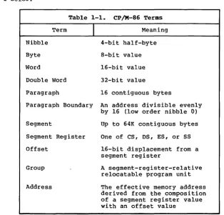
Several terms used throughout this manual are defined in Table 1-1 below:
Table 1-1. CP/M-86 Terms
Term
I
MeaningNibble 4-bit half-byte
Byte a-bit value
Word l6-bit value
Double Word 32-bit value
Paragraph 16 contiguous bytes
Paragraph Boundary An address divisible evenly by 16 (low order nibble 0)
Segment Up to 64K contiguous bytes
Segment Register One of CS, DS, ES, or SS
Offset l6-bit displacement from a segment register
Group A segment-register-relative relocatable program unit
[image:9.470.60.375.181.483.2]CP/M-86 System Guide 1.1 CP/M-86 General Characteristics
CP/M-86 supports eight program groups: the code, data, stack and extra groups as well as four auxiliary groups. When a code, data, stack or extra group is loaded, CP/M-86 sets the respective segment register (CS, DS, SS or ES) to the base of the group. CP/M-86 can also load four auxiliary groups. A transient program manages the location of the auxiliary groups using values stored by CP/M-86 in the user's base page.
1.2 CP/M-80 and CP/M-86 Differences
The structure of CP/M-86 is as clOSe to CP/M-80 as possible in order to provide a familiar programming environment which allows application programs to be transported to the 8086 and 8088 processors with minimum effort. This section points out the specific differences between CP/M-80 and CP/M-86 in order to reduce your time in scanning this manual if you are already familiar with CP/M-80. The terms and concepts presented in this section are explained in detail throughout this manual, so you will need to refer to the Table of Contents to find relevant sections which provide specific definitions and information.
Due to the nature of the 8086 processor, the fundamental difference between CP/M-80 and CP/M-86 is found in the management of the various relocatable groups. Although CP/M-80 references absolute memory locations by necessity, CP/M-86 takes advantage of the static relocation inherent in the 8086 processor. The operating system i tsel f is usually loaded directly above the interrupt locations, at location 0400H, and relocatable transient programs load in the best fit memory region. However, you can load CP/M-86 into any portion of memory without changing the operating system (thus, there is no MOVCPM utility with CP/M-86), and transient programs will load and run in any non-reserved region.
Three general memory models are presented below, but if you are converting 8080 programs to CP/M-86, you can use either the 8080 Model or Small Model and leave the Compact Model for later when your addressing needs increase. You"ll use GENCMD, described in Section 3.2, to produce an executable program file from a hex file. GENCMD parameters allow you to specify which memory model your program requires.
CP/M-86 System Guide 1.2 CP/M-80 and CP/M-86 Differences
If you"ve implemented CP/M-80 Version 2, you already have disk definition tables which will operate properly with CP/M-86. You may wish to attach different disk drives, or experiment with sector skew factors to increase performance. If so, you can use the new GENDEF utility which performs the same function as the DISKDEF macro used by MAC under CP/M-80. You"ll find, however, that GENDEF provides you with more information and checks error conditions better than the DISKDEF macro.
Although generating a CP/M-86 system is generally easier than generating a CP/M-80 system, complications arise if you are using single-density floppy disks. CP/M-86 is too large to f.it in the two-track system area of a single-density disk, so the bootstrap operation must perform two steps to load CP/M-86: first the bootstrap must load the cold start loader, then the cold start loader loads CP/M-86 from a system file. The cold start loader includes a LDBIOS which is identical to your CP/M-86 BIOS with the exception of the INIT entry point. You can simplify the LDBIOS if you wish because the loader need not write to the disk. If you have a double-density disk or reserve enough tracks on a single-density disk, you can load CP/M-86 without a two-step boot.
To make a BDOS system call, use the reserved software interrupt #244. The jump to the BDOS at location 0005 found in CP/M-80 is not present in CP/M-86. However, the address field at offset 0006 is present so that programs which "size" available memory using this word value will operate without change. CP/M-80 BDOS functions use certain 8080 registers for entry parameters and returned values. CP/M-86 BDOS functions use a table of corresponding 8086 registers. For example, the 8086 registers CH and CL correspond to the 8080 registers Band C. Look through the list of BDOS function numbers in Table 4-2. and you"ll find that functions 0, 27, and 31 have changed slightly. Several new functions have been added, but they do not affect existing programs.
One major philosophical difference is that in CP/M-80, all addresses sent to the BDOS are simply l6-bit values in the range OOOOH to OFFFFH. In CP/M-86, however, the addresses are really just 16-bit offsets from the DS (Data Segment) register which is set to the base of your data area. If you translate an existing CP/M-80 program to the CP/M-86 environment, your data segment will be less than 64K bytes. In this case, the DS register need not be changed following ini tia1 load, and thus all CP /M-80 addresses become simple DS-re1ative offsets in CP/M-86.
CP/M-86 System Guide 1.2 CP/M-80 and CP/M-86 Differences
Section 2
Command Setup and Execution Under CP/M-86
This section discusses the operation of the Console Command Processor (CCP), the format of transient programs, CP/M-86 memory models, and memory image formats.
2.1 CCP Built-in and Transient Commands
The operation of the CP/M-86 CCP is similar to that of CP/M-80. Upon initial cold start, the CP/M sign-on message is printed, drive A is automatically logged in, and the standard prompt is issued at the console. CP/M-86 then waits for input command lines from the console, which may include one of the built-in commands
DIR ERA REN TYPE USER
(note that SAVE is not supported under CP/M-86 since the equivalent function is performed by DDT-86).
Alternatively, the command line may begin with the name of a transient program with the assumed file type "CMD" denoting a "command file." The CMD file type differentiates transient command files used under CP/M-86 from COM files which operate under CP/M-80.
The CCP allows mul tiple programs to reside in memory, providing facili ties for background tasks. A transient program such as a debugger may load additional programs for execution under its own control. Thus, for example, a background printer spooler could first be loaded, followed by an execution of DDT-86. DDT-86 may, in turn, load a test program for a debugging session and transfer control to the test program between breakpoints. CP/M-86 keeps account of the order in which programs are loaded and, upon encountering a CONTROL-C, discontinues execution of the most recent program activated at the CCP level. A CONTROL-C at the DDT-86 command level aborts DDT-86 and its test program. A second CONTROL-C at the CONTROL-CCONTROL-CP level aborts the background printer spooler. A third CONTROL-C resets the disk system. Note that program abort due to CONTROL-C does not reset the disk system, as is the case in CP/M-80. A disk reset does not occur unless the CO~TROL-C occurs at the CCP command input level with no programs residing in memory.
When CP/M-86 receives a request to load a transient program from the CCP or another transient program, it checks the program~s
CP/M-86 System Guide 2.2 Transient Program Execution Models
2.2 Transient Program Execution Models
The initial values of the segment registers are determined by one of three nmemory models n used by the transient program, and described in the CMD file header. The three memory models are summarized in Table 2-1 below.
Table 2-1. CP/M-86 Memory Models
Model
I
Group Relationships8080 Model Code and Data Grou~s Overlap
Small Model Independent Code and Data Groups
Compact Model Three or More Independent Groups
The 8080 Model supports programs which are directly translated from CP/M-80 when code and data areas are intermixed. The 8080 model consists of one group which contains all the code, data, and stack areas. Segment registers are initialized to the starting address of the region containing this group. The segment registers can, however, be managed by the appl ication program dur ing execution so that multiple segments within the code group can be addressed.
The Small Model is similar to that defined by Intel, where the program consists of an independent code group and a data group. The Small Model is sui table for use by programs taken from CP/M-80 where code and data is easily separated. Note again that the code and data groups often consist of, but are not restricted to, single 64K byte segments.
The Compact Model occurs when any of the extra, stack, or auxiliary groups are present in program. Each group may consist of one or more segments, but if any group exceeds one segment in size, or if auxiliary groups are present, then the application program must manage its own segment registers during execution in order to address all code and data areas.
CP/M-86 System Guide 2.3 The 8080 Memory Model
2.3 The 8080 Me.ory Model
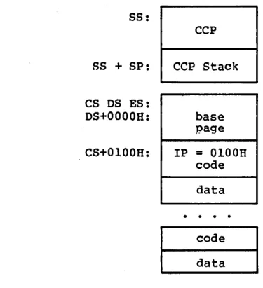
The 8080 Model is assumed when the transient program contains only a code group. In this case, the CS, DS, and ES registers are initialized to the beginning of the code group, while the SS and SP registers remain set to a 96-byte stack area in the CCP. The Instruction Pointer Register (IP) is set to 100H, similar to CP/M-80, thus allowing base-page values at the beginning of the code group. Following program load, the 8080 Model appears as shown in Figure 2-1, where low addresses are shown at the top of the diagram:
SS:
CCP
SS + SP: CCP Stack
CS DS ES:
DS+OOOOH: base page
CS+0100H: IP
=
0100H codedata
code
data
Figure 2-1. CP/M-86 8080 Memory Model
The intermixed code and data regions are indistinguishable. The "base page" values, descr ibed below, are identical to CP IM-80, allowing simple translation from 8080, 8085, or Z80 code into the 8086 and 8088 environment. The following ASM-86 example shows how to code an 8080 model transient program.
eseg
org 100h
(code) endcs equ $
dseg
org offset endcs
[image:16.469.114.302.156.362.2]CP/M-86 System Guide 2.4 The Small Memory Model
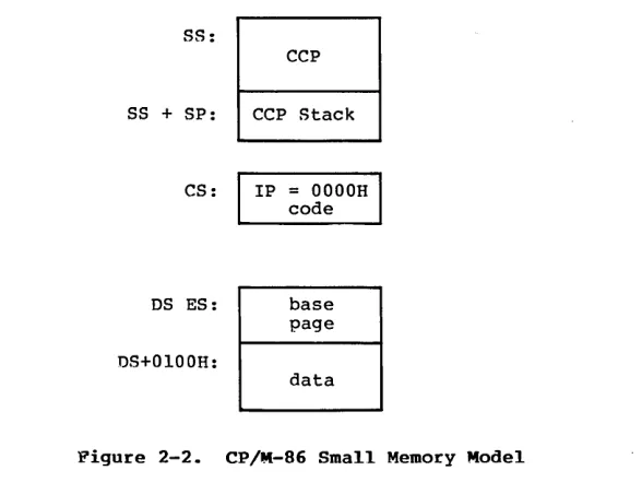
2.4 The Small Memory Model
The Small Model is assumed when the transient program contains both a code and data group. (In ASM-B6, all code is generated following a CSEG directive, while data is defined following a D~EG
directive with the origin of the data segment independent of the code segment.) In this model, CS is set to the beginning of the code group, the DS and ES are set to the start of the data group, and the SS and SP registers remain in the CCP~s stack area as shown in Figure 2-2. '
S8:
SS + SP:
CS:
DS ES:
DS+OlOOH:
CCP
CCP Stack
IP = OOOOH code
base page
data
Figure 2-2. CP/M-86 Small Memory Model
The machine code begins at CS+OOOOH, the "base page" values begin at DS+OOOOH, and the data area starts at DS+OlOOH. The following ASM-86 example shows how to code a small model transient program.
cseg
(code) dseg
[image:17.468.88.382.149.375.2]CP/M-86 System Guide 2.5 The Compact Memory Model
2.5 The Compact Memory Model
The Compact Model is assumed when code and data groups are present, along with one or more of the remaining stack, extra, or auxiliary groups. In this case, the CS, OS, and ES registers are set to the base addresses of their respective areas. Figure 2-3 shows the initial configuration of segment registers in the Compact Model. The values of the various segment registers can be programmatically changed during execution by loading from the initial values placed in base page by the CCP, thus allowing access to the entire memory space.
If the transient program intends to use the stack group as a stack area, the SS and SP registers must be set upon entry. The SS and SP registers remain in the CCP area, even if a stack group is defined. Although it may appear that the SS and SP registers should be set to address the stack group, there are two contradictions. First, the transient program may be using the stack group as a data area. In that case, the Far Call instruction used by the CCP to transfer control to the transient program could overwrite data in the stack area. Second, the SS register would logically be set to the base of the group, while the SP would be set to the offset of the end of the group. However, if the stack group exceeds 64K the address range from the base to the end of the group exceeds a 16-bit offset value.
The following ASM-86 example shows how to code a compact model transient program.
cseg
(code) dseg
org IOOh
(data) eseg
(more data) sseg
CP/M-86 System Guide 2.5 The Compact Memory Model
SS:
CCP
SS + SP: CCP Stack
CS: IP
=
OOOOHcode
DS: base
page
OS+OlOOH:
data
ES:
data
CP/M-86 System Guide 2.6 Base Page Initialization
2.6 Base Page Initialization
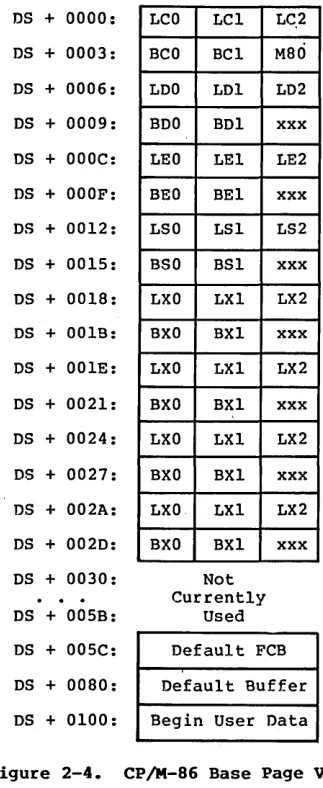
Similar to CP/M-80, the CP/M-86 base page contains default values and locations init'ialized by the CCP and used by the transient program. The base page occupies the regions from offset OOOOH through OOFFH relative to· the DS register. The values in the base page for CP/M-86 include those of CP/M-80, and appear in the same relative positions, as shown in Figure 2-4.
DS + 0000:
DS + 0003:
DS + 0006:
DS + 0009:
DS + OOOC:
DS + OOOF:
DS + 0012:
DS + 0015:
DS + 0018:
DS + 001E:
DS + 001E:
DS + 0021:
DS + 0024:
DS + 0027:
DS + 002A:
DS + 002D:
DS + 0030:
DS + 005B:
DS + 005C:
DS + 0080:
DS + 0100:
LCO LC1
BCO BC1
LDO LD1
BDO BD1
LEO LE1
BEO BEl
LSO LSI
BSO BS1
LXO LX1
BXO BXI
LXO LX1
BXO BX1
LXO LX1
BXO BX1
LXO LX1
BXO BX1
Not Currently
Used LC.2
M80
LD2
xxx
LE2
xxx
LS2
xxx
LX2
xxx
LX2
xxx
LX2
xxx
LX2
xxx
Default FCB
Default Buffer
Begin User Data
[image:20.469.147.309.136.531.2]CP/M-86 System Guide 2.6 Base Page Initialization
Each byte is indexed by 0, 1, and 2, corresponding to the standard Intel storage convention of low, middle, and high-order (most significant) byte. "xxx" in Figure 2-4 marks unused bytes. LC is the last code group location (24-bits, where the 4 high-order bits equal zero).
In the 8080 Model, the low order bytes of LC (LCO and LCI) never exceed OFFFFH and the high order byte (LC2) is always zero. BC is base paragraph address of the code group (16-bits). LO and BO provide the last position and paragraph base of the data group. The last position is one byte less than the group length. It should be noted that bytes LOO and LOI appear in the same relative positions of the base page in both CP/M-80 and CP/M-86, thus easing the program translation task. The M80 byte is equal to 1 when the 8080 Memory Model is in use. LE and BE provide the length and paragraph base of the optional extra group, while LS and BS give the optional stack group length and base. The bytes marked LX and BX correspond to a set of four optional independent groups which may be required for programs which execute using the Compact Memory Model. The initial values for these descriptors are derived from the header record in the memory image file, described in the following section.
2.7 Transient Program Load and Exit
Similar to CP/M-80, the CCP parses up to two filenames following the command and places the properly formatted FCB's at locations OOSCH and 006CH in the base page relative to the OS register. Under CP/M-80, the default OMA address is initialized to 0080H in the base page. Due to the segmented memory of the 8086 and 8088 processors, the OMA address is divided into two parts: the OMA segment address and the OMA offset. Therefore, under CP/M-86, the default DMA base is initialized to the value of OS, and the default OMA offset is initialized to 0080H. Thus, CP/M-80 and CP/M-86 operate in the same way: both assume the default OMA buffer occupies the second half of the base page.
Section 3
Command (CMD) File Generation
As mentioned previously, two utili ty proqrams are provided wi th CP/M-86, called GENCMD and LMCMD, which are used to produce CMD memory image files suitable for execution under CP/M-86. GENCMD accepts Intel 8086 "hex" format files as input, while LMCMD reads Intel L-module files output from the standard Intel LOC86 Object Code Locator utility. GENCMD is used to process output from the Digital Research ASM-86 assembler and Intel~s OH86 utility, while LMCMD is used when Intel compatible developmental software is available for generation of programs targeted for CP/M-86 operation.
3.1 Intel 8086 Hex File Format
GENCMD input is in Intel "hex" format produced by both the Dig i ta 1 Research ASM-86 assembler and the standard Intel OH86 utility program (see Intel document #9800639-03 entitled "MCS-86 Software Development utitities Operating Instructions for ISIS~II
Users"). The CMD file produced by GENCMD contains a header record which defines the memory model and memory size requirements for loading and executing the CMD file.
An Intel "hex" file consists of the traditional sequence of ASCII records in the following format:
CP/M-86 System Guide 3.1 Intel Hex File Format
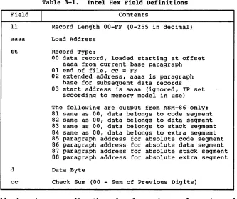
Table 3-1. Intel Hex Field Definitions
Field
I
Contents11 Record Len~th OO-FF (0-255 in decimal)
aaaa Load Address
tt Record Type:
d
cc
00 data record, loaded starting at offset aaaa from current base paragraph 01 end of file, cc = FF
02 extended address, aaaa is paragraph base for subsequent data records 03 start address is aaaa (ignored, IP set
according to memory model in use)
The following are output from ASM-86 only: 81 same as 00, data belongs to code segment 82 same as 00, data belongs to data segment 83 same as 00, data belongs to stack segment 84 same as 00, data belongs to extra segment 85 paragraph address for absolute code segment 86 paragraph address for absolute data segment 87 paragraph address for absolute stack segment 88 paragraph address for absolute extra segment
Data Byte
Check Sum (00 - Sum of Previous Digits)
All characters preceding the colon for each record are ignored. (Additional hex file format information is included in the ASM-86 User~s Guide, and in Intel~s document i9800821A entitled "MCS-86 Absolute Obj.ect File Formats.")
3.2 Operation of GENCMD
The GENCMD utility is invoked at the CCP level by typing
GENCMD filename parameter-list
[image:23.468.60.393.52.333.2]CP/M-86 System Guide 3.2 Operation of GENCMD
The 8080 keyword forces a single code group so that the BDOS load function sets up the 8080 Memory Model for execution, thus allowing intermixed code and data within a single segment. The form of this command is
GENCMD filename 8080
The remaining keywords follow the filename or the 8080 option and define specific memory requirements for each segment group, corresponding one-to-one with the segment groups def ined in the previous section. In each case, the values corresponding to each group are enclosed in square brackets and separated by commas. Each value is a hexadecimal number representing a paragraph address or segment length in paragraph units denoted by hhhh, prefixed by a single letter which defines the meaning of each value:
Ahhhh Bhhhh Mhhhh Xhhhh
Load the group at absolute location hhhh The group starts at hhhh in the hex file
The group requires a minimum of hhhh
*
16 bytes The group can address a maximum of hhhh*
16 bytesGenerally, the CMD file header values are derived directly from the hex file and the parameters shown above need not be included. The following si tuations, however, require the use of GENCMD parameters.
• The 8080 keyword is included whenever ASM-86 is used in the conversion of 8080 programs to the 8086/8088 environment when code and data are intermixed within a single 64K segment, regardless of the use of CSEG and DSEG directives in the source program.
• An absolute address (A value) must be given for any group which must be located at an absolute location. Normally, this value is not specified since CP/M-86 cannot generally ensure that the required memory region is available, in which case the CMD file cannot be loaded.
• The B value is used when GENCMD processes a hex file produced by Intel~s OH86, or similar· utility program that contains more than one group. The output from OH86
consists of a sequence of data records with no
CP/M-8G System Guide 3.2 Operation of GENCMD
• The minimum memory value (M value) is included only when the hex records do not define the minimum memory requirements for the named group. Generally, the code group size is determined precisely by the data records loaded into the area. That is, the total space required for the group is defined by the range between the lowest and highest data byte addresses. The data group, however, may contain uninitia1ized storage at the end of the group and thus no data records are present in the hex file which define the highest referenced data item. The highest address in the data group can be defined withln the source program by including a "DB 0" as the last data item. Alternatively, the M value can be included to allocate the additional space at the end of the group. Similarly, the stack, extra, and auxiliary group sizes must be defined using the M value unless the highest addresses wi thin the groups are implicitly def ined by data records in the hex file •
• The maximum memory size, given by the X value, is generally used when additional free memory may be needed for such purposes as I/O buffers or symbol tables. If the data area size is fixed, then the X parameter need not be included. In this case, the X value is assumed to be the same as the M value. The value XFFFF allocates the largest memory region available but, if used, the transient program must be aware that a three-byte length field is produced in the base page for this group where the high order byte may be non-zero. Programs converted directly from CP/M-80 or programs that use a 2-byte pointer to address buffers should restrict this value to XFFF or less, producing a maximum allocation length of OFFFOH bytes.
The following GENCMD command line transforms the file X.HSG into the file X.CMD with the proper header record:
gencmd x code[a40] data[m30,xfff]
CP/M-86 System Guide 3.2 Operation of GENCMD
Assuming a file Y.H86 exists on drive B containing Intel hex records with no interspersed segment information, the command
gencmd b:y data[b30,m20] extra[b50] stack[m40] x1[m40]
produces the file Y.CMD on drive B by selecting records beginning at address OOOOH for the code segment, with records starting at 300H allocated to the data segment. The extra segment is filled from records beginning at 500H, while the stack and auxiliary segment #1 are uninitia1ized areas requiring a minimum of 400H bytes each. In this example, the data area requires a minimum of 200H bytes. Note again, that the B value need not be included if the Digital Research ASM-86 assembler is used.
3.3 Operation of LMCMD
CP/M-86 System Guide 3.4 Command (CMD) File Format
3.4 Command (CMD) File Format
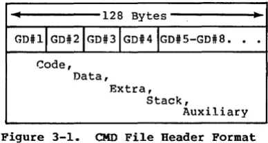
The CMD file produced by GENCMD and LMCMD consists of the l28-byte header record followed immediately by the memory image. Under normal circumstances, the format of the header record is of no consequence to a programmer. For completeness, however, the various fields of this record are shown in Figure 3-1.
•
128 Bytes.,
GDilIGDi2IGDi3IGD#4IGDiS-GDi8.
. .
Code, Data,
Extra, Stack,
Auxiliary
Figure 3-1. CMD File Header Format
In Figure 3-1, GDi2 through GDi8 represent "Group Descriptors." Each Group "Descriptor corresponds to an independently loaded program unit and has the following fields:
8-bit l6-bit l6-bit l6-bit l6-bit
I
G-FormI
G-Length A-Base G-Min G-Maxwhere G-Form describes the group foimat, or has the value zero if no more descriptors follow. If G-Form is non-zero, then the 8-bit value is parsed as two fields:
G-Form: 4-bit 4-bit
I
x x x xI
G-TypeI
[image:27.470.131.325.140.244.2]CP/M-86 System Guide 3.4 Command (CMD) File Format
Table 3-2. Group Descriptors
G-Type
I
Group Type1 Code Group 2 Data Group 3 Extra Group 4 Stack Group
5 Auxiliary Group #1 6 Auxiliary Group #2 7 Auxiliary Group #3 8 Auxiliary Group #4 9 Shared Code Group 10 - 14 Unused, but Reserved
15 Escape Code for Additional Types
All remalnlng values in the group descriptor are given in increments of 16-byte paragraph units with an assumed low-order 0 nibble to complete the 20-bit address. G-Length gives the number of paragraphs in the group. Given a G-length of 0080H, for example, the size of the group is 00800H
=
20480 bytes. A-Base defines the base paragraph address for a non-relocatable qroup while G-Min and G-Max define the minimum and maximum size of the memory area to allocate to the qroup. G-Type 9 marks a "pure" code g roup for use under MP /M-86 and future versions of CP /M-86. Presently a Shared Code Group is treated as a non-shared Program Code Group under CP/M-86.The memory model described by a header record is implicitly determined by the Group Descriptors. The 8080 Memory Model is assumed when only a code group is present, since no independent data group is named. The Small Model is implied when both a code and data group are present, but no additional group descriptors occur. Otherwise, the Compact Model is assumed when the CMD file
Section 4
Basic Disk Operating System Functions
This section presents the interface conventions which allow transient program access to CP/M-86 BDOS and BIOS functions. The BDOS calls correspond closely to CP/M-80 Version 2 in order to simplify translation of existing CP/M-80 programs for operation under CP/M-86. BDOS entry and exit conditions are described first, followed by a presentation of the individual BDOS function calls.
4.1 Bnos Parameters and Function Codes
Entry to the BDOS is accomplished through the 8086 software interrupt #224, which is reserved by Intel Corporation for use by CP/M-86 and MP/M-86. The function code is passed in register CL with byte parameters in DL and word parameters in DX. Single byte values are returned in AL, word values in both AX and BX, and double word values in ES and BX. All segment registers, except ES, are saved upon entry and restored upon exit from the BDOS (corresponding to PL/M-86 conventions). Table 4-1 summarizes input and output parameter passing:
Table 4-1. BDOS Parameter Summary
BDOS Ehtry Registers
I
BDOS Return RegistersCL Function Code Byte value returned in AL
DL Byte Parameter Word value returned in both AX and BX DX Word Parameter Double-word value returned with DS Data Segment offset in BX and
segment in ES
Note that the CP/M-80 BDOS requires an n information address" as
CP/M-86 System Guide 4.1 BDOS Parameters and Function Codes
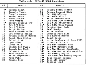
A list of CP/M-86 calls is given in Table 4-2 with an asterisk following functions which differ from or are added to the set of. CP/M-80 Version 2 functions.
Table 4-2. CP/M-86 Bnos Functions
F#
I
Result0* System Reset 1 Console Input 2 Console Output 3 Reader Input 4 Punch Output 5 List Output
6* Direct Console I/O 7 Get I/O Byte 8 Set I/O Byte 9 Print String
10 Read Console Buffer 11 Get Console Status 12 Return Version Number 13 Reset Disk System 14 Select Disk 15 Open File 16 Close File 17 Search for First 18 Search for Next 19 Delete File 20 Read Sequential 21 Write Sequential 22 Make File
23 Rename File
F#
I
Result24 Return Login Vector 25 Return Current Disk 26 Set DMA Address 27* Get Addr(Alloc) 28 write Protect Disk 29 Get Addr(R/O Vector) 30 Set File Attributes 31* Get Addr(Disk Parms) 32 Set/Get User Code 33 Read Random 34 Write Random 35 Compute File Size 36 Set Random Record 37* Reset drive
40 Write Random with Zero Fill 50* Direct BIOS Call
51* Set DMA Segment Base 52* Get DMA Segment Base 53* Get Max Memory Available 54* Get Max Mem at Abs Location 55* Get Memory Region
56* Get Absolute Memory Region 57* Free memory region
58* Free all memory 59* Program load
[image:31.468.56.401.102.372.2]CP/M-86 System Guide 4.2 Simple BOOS Calls
4.2
SimpleBnos
CallsThe first set of BOOS ·functions cover the range 0 through 12, and perform simple functions such as system reset and single character I/O.
Entry
CL: OOH
DL: Abort Code
."
ReturnFUNCTION 0
SYSTEM RESET
The system reset function returns control to the CP/M operating system at the CCP command level. Th~abort code in DL has two possible values: if DL = OOH then the currently active program is terminated and control is returned to the CCP. If OL is a 01H, the program remains in memory and the memory allocation state remains unchanged.
Entry Return
CL: 01H FUNCTION 1 AL: ASCII Character
CONSOLE INPUT
,
The console input function reads the next character from the logical console device (CONSOLE) to register AL. Graphic characters, along with carriage r~turn, line feed, and backspace (CONTROL-H) are echoed to the console. ~ab characters (CONTROL-I) are expanded in columns of eight characters. The BOOS does not return to the da1ling program until a character has been typed, thus suspending execution if a character is not ready.
Entry
CL: 02H
DL: ASCII
Character
,
Return
FUNCTION 2
CONSOLE OUTPUT
CP/M-86 System Guide 4.2 Simple BDOS Calls
Entry Retur.n
•
CL: 03H FUNCTION 3 AL: ASCII Character
READER INPUT
,~---~
The ~eader Input function reads the next character from the logical reader (READER) into register AL'. Control does not return until the character has been read.
Entry
CL: 04H
DL: ASCII
Character
,
Return
,
FUNCTION 4
PUNCH OUTPUT
The Punch Output function sends the character from register DL to the logical punch device (PUNCH).
Entry
CL: OSH
D~: ASCII Character
~
....
Return
"
FUNCTION S
LIST OUTPUT
CP/M-86 System Guide
Entry
CL: 06H
DL: OFFH or OFEH
or char
( input)
(status)
(output)
4.2 Simple BDOS Calls
Return
FUNCTION 6 AL: char or status
DIRECT CONSOLE I/O (no value)
Direct console I/O is supported under CP/M-86 for those specialized applications where unadorned console input and output is required. Use of this function should, in general, be avoided since it bypasses all of CP/M-86's normal control character functions (e.g., CONTROL-S and CONTROL-P). Programs which perform direct I/O through the BIOS under previous releases of CP/M-80, however, should be changed to use direct I/O under the BDOS so that they can be fully supported under future releases of MP/M'M and CP/M.
Upon entry to function 6, register DL either contains (1) a hexadecimal FF, denoting a CONSOLE input request, or (2) a hexadecimal FE, denoting a CONSOLE status request, or (3) an ASCII character to be output to CONSOLE where CONSOLE is the logical console device. If the input value is FF, then function 6 directly calls the BIOS console input primitive. The next console input character is returned in AL. If the input value is FE, then function 6 returns AL = 00 if no character is ready and AL
=
FF otherwise. If the input value in DL is not FE or FF, then function 6 assumes tha t DL contains a valid ASCII character which is sent to the console.Entry Return
\.
CL: 07H FUNCTION 7 AL: I/O Byte Value
\. GET I/O BYTE
CP/M-86 System Guide
Entry
CL: 08H
DL: I/O Byte Value
4.2 Simple BDOS Calls
Return
FUNCTION 8
SET I/O BYTE
The Set I/O Byte function changes the system IOBYTF. value to that given in register DL. This fUnction allows transient program access to the IOBYTE in order to modify the current assignments for the logical devices CONSOLE, READER, PUNCH, and LIST.
Entry
CL: 09H
DX: String Offset
"
Return
"
FUNCTION 9
PRINT STRING
The Print String function sends the character string stored in memory at the location given by DX to the logical console device (CONSOLE), until a "$" is encountered in the string. Tabs are expanded as in fUnction 2, and checks are made for start/stop scroll and printer echo.
Entry
CL: OAH
DX: Buffer Offset
FUNCTION 10
"READ CONSOLE BUFFER
Return
Console Characters
CP/M-86 System Guide 4.2 Simple BOOS Calls
The Read Buffer function reads a line of edited console input into a buffer addressed by register
ox
from the logical console device (CONSOLE). Console input is terminated when either the input buffer is filled or when a return (CONTROL-M) or a line feed (CONTROL-J) character is entered. The input buffer addressed by DX takes the form:DX: +0 +1 +2 +3 +4 +5 +6 +7 +8 +n
where "mx" is the maximum number of characters which the buffer will hold, and "nc" is the number of characters placed in the buffer. The characters entered by the operator follow the "nc" value. rrhe value "mx" must be set prior to making a function 10 call and may range in value from 1 to 255. Setting'mx to zero is equivalent to setting rnx to one. The vaiue "nc" is returned to the user and may range from 0 to mx. If nc < mx,then uninitialized positions follow the last character, denoted by"??" in the above figure. Note that a terminating return or line feed character is not placed in the buffer and not included in the count "nc".
A number of editing control functions are supported during console input under function 10. rrhese are summarized in Table 4-3.
Table 4-3. Line Editing Controls
Keystroke
I
Resultrub/del CONTROL-C CONTROL-E CONTROL-H CONTROL-J CONTROL-M CONTROT .. -R CONTROL-U CONTROL-X
removes and echoes the last character reboots when at the beginning of line causes physical end of line
backspaces one character position (line feed) terminates input line (retur.no) terminates input line
retvpei the current line after new line removes current line after new line backspaces to beginning of current line
CP/M-86 System Guide
Entry
CL: OBH FUNCTION 11
GET CONSOLE STA~Ug
4.2 Simple BOOS Calls
Return
AL: Console Status
The Console Status function checks to see if a character has been typed at the logical console device (CONSOLE). If a character is ready, the value OlH is returned in register AL. Otherwise a OOH value is returned.
Entry Return
1\
,
CL:OCH FUNCTION 12 BX: Version Number
RETURN VERSION NUMBER
Function 12 provides information which alJ ows version independent programming. A two-byte value is returned, with BH = 00 designating the CP/M re:lease (BE = 01 for MP/l'vt), and BL = 00 for all releases previous to 2.0. CP/M 2.0 returns a hexadecimal 20 in register EL, with subsequent version 2 releases in the hexadecimal range 21, 22, through 2F. To provide version number compatibility, the initial ~elease of CP/M-86 returns a 2.2.
4.3 aDOS Pile Operations
CP/M-S6 System Guide 4.3 BOOS File Operations
00 01 02
where
dr
OS 09 10 11 12 13 14 15 16
drive code (0 - 16)
o
=> use default drive for file 1 => auto disk select drive A, 2 => auto disk select drive B,16=> auto disk seiect drive P.
f1 ••• fS contain the file name in ASCII upper case, with high bit =,0
,t1,t2,t3 contain the file type in ASCII upper case, with high bit = 0 t1', t2', and t3' denote the high bit of these positions,
tl' = 1 => Read/Only file,
t2' = 1 => SYS file, no DIR list
31 32 33 34 35
ex contains the current extent number, normally set to 00 by the user, but in range 0 - 31 during file I/O
sl reserved for internal system use
s2 reserved for internal system use, set to zero on call to OPEN, MARE, SEARCH
rc record count for extent nex,n takes on values from 0 - 12S
dO ••• dn filled-in bV CP/M, reserved for system use
cr current record 'to read or write in a sequential file operation, normally set to zero by user
rO,r1,r2 optional random redQrd number in the range 0-65535, with overflow to r2, rO,r1 constLtute a 16-bit value with low byte rO, and high'byte r1
CP/M-86 System Guide 4.3 BOOS File Operations
There are three error situations that the BOOS may encounter during file processing, initiated as a result of a BOOS File I/O function call. When one of these cond i tions is detected, the BOOS issues the following message to the console:
BOOS ERR ON x: error
where x is the drive name of the drive selected when the error condition is detected, and "error" is one of the three messages:
BAO SECTOR SELECT R/O
These error situations are trapped by the BOOS, and thus the executing transient program is temporarily halted when the error is detected. No indication of the error situation is returned to the transient program.
The "BAO SECTOR" error is issued as the result of an error condi tion returned to the BOOS from the BIOS module. The BOOS makes BIOS sector read and write commands as part of the execution of BOOS file related system calls. If the BIOS read or write routine detects a hardware error, it returns an error code to the BOOS resulting in this error message. The operator may respond to this error in two ways: a CONTROL-C terminates the executing program, while a RETURN instructs CP/M-86 to ignore the error and allow the program to continue execution.
The "SELECT" error is also issued as the result of an error condi tion returned to the BOOS from the BIOS module. The BOOS makes a BIOS disk select call prior to issuing any BIOS read or write to a particular drive. If the selected drive is not supported in the BIOS module, it returns an error code to the BOOS resulting in this error message. CP/M-86 terminates the currently running program and returns to the command level of the CCP following any input from the console.
CP/M-86 System Guide 4.3 BDOS File Operations
Entry Return
,~---~~
CL: ODH FUNCTION 13
RESET DISK SYSTEM
\
The Reset Disk Function is used to programmatically restore the file system to a reset state where all disks are set to read/write (see functions 28 and 29), only disk drive A is selected. This function can be used, for example, by an application program which requires disk changes during operation. Function 37 (Reset Drive) can also be used for this purpose.
Entry Return
~r---~~
CL: OEH FUNCTION 14
DL: Selected,
Disk ~---~ SELECT DISK
The Select Disk function designates the disk drive named in register DL as the default disk for subsequent file operations, with DL = 0 for dr i ve A, 1 for dr i ve B, and so-for th through 15 corresponding to drive P in a full sixteen drive system. In addition, the designated drive is logged-in if it is currently in the reset state. Logging-in a drive places it in "on-line" status which activates the drive~s directory until the next cold start, warm start, disk system reset, or drive reset operation. FCB's which specify drive code zero (dr = OOH) automatically reference the currently selected default drive. Drive code values between 1 and 16, however, ignore the selected default drive and directly reference drives A through P.
Entry
CL: OFH
DX: FeB
Offset \
Return
,
FUNCTION 15 AL: Return Code
OPEN FILE
CP/M-86 System Guide 4.3 BOOS File Operations
If a directory element is matched, the relevant directory information is copied into bytes dO through dn of the FCB, thus allowing access to the files through subsequent read and write operations. Note that an existing file must not be accessed until a successful open operation is completed. Further, an 'FCB not activated by either an open or make function must not be used in BOOS read or write commands. Upon return, the open function returns a "directory code" with the value 0 through 3 if the open was successful, or OFFH (255 decimal) if the file cannot be' found. If question marks occur in the FCB then the first matching 'FCB is activated. Note that the current record ("cr") must be zeroed by the program if the file is to be accessed sequentially from the first record.
Entry
CL: 10H
OX: FCB Offset \
Return
"
FUNCTION 16 AL: Return Code
CLOSE FILE
CP/M-86 System Guide
Entry
Ji
CL: 11H
DX: FCB Offset
FUNCTION 17
SEARCH FOR FIRST
4.3 aDOS File Operations
Return
Ji
AL: Directory Code
Search First scans the directory for a match with the file given by the FCB addressed bV DX. The value 255 (hexadecimal FF) is returned if the file is not found, otherwise 0, 1, 2, or 3 is returned indicating the file is present. In the case that the file is found, the buffer at the current DMA address is filled with the record containing the directory entry, and its relative starting position is AL
*
32 (i.e., rotate the AL register left 5 bits).1\1 though not normally required for application programs, the directory information can be extracted from the buffer at this position.
An ASCII question mark (63 decimal, 3F hexadecimal) in any position from "f1" through "ex" matches the corresponding field of any directory entry on the default or auto-selected disk drive. If the "dr" field contains an ASCII question mark, then the auto disk select function is disabled, the default disk is searched, with the search function returning any matched entry, allocated or free, belonging to any user number. This latter function is not normally used by application programs, but does allow complete f1exibi1i ty to scan all current directory values. If the "dr" field is not a question mark, the "s2" byte is automatically zeroed.
Entry
Ji
CL: 12H FUNCTION 18
SEARCH FOR NEXT
Return
AL: Directory Code
CP!M-86 System Guide 4.3 BDOS F~le Operations
Entry
I'.
•
"
ReturnCL: 13H FUNCTION 19 AL: Return Code
DX: FCB
"-Offset DELETE FILE
The Delete File function removes files which match the FCB addressed by
ox.
The filename and type may contain ambiguous references (i.e., question marks in various positions), but the drive select code cannot be ambiguous, as in the Search and Search Next functions. Function 19 returns a OFFH (decimal 255) if the referenced file or files cannot be found, otherwise a value of zero is returned.Entry Return
"
"
CL: 14H FUNCTION 20 AL: Return CodeOX: FCB "- READ SEQUENTIAL Offset
CP/M-86 System Guide
Entry
CL: l5H
OX: FCB Offset
4.3 BOOS File Operations
Return
FUNCTION 21 AL: Return Code
WRITE SEQUENTIAL
Given that the FCB addressed by DX has been activated through an open or make function (numbers 15 and 22), the write Sequential function writes the 128 byte data record at the current OMA address to the file named by the FCB. The record is placed at position ncr" of the file, and the ncr" field i~ au~omatically incremented to the next record position. If the "cr" field overflows then the next logical extent is automatically opened and the "cr" field is reset to zero in preparation for the next write o-peration.' write operations can take place into an existing file, in which case newly written records overlay those which already exist in the file. The ncr" field must be set to zero following an open or make call by the user if the intent is to write sequentially from the beginning of the file. Register AL
=
OOH upon return from a successful write operation, while a non-zero value indicete& an unsuccessful writ~ due to one of the following conditions:01 No available directory space - This condition occurs when the write command attempts to create a new extent that requires a new directory entry and no available directory entries exist on the selected disk drive.
02 No available data block - This condition is encountered when the write command attempts to allocate a new data block to the file and no unallocated data blocks exist on the selected disk drive.
Entry
CL: l6H
OX: FCB
Offset
,
Return
"
FUNCTION 22 AL: Return Code
MAKE FILE
CP/M-86 System Guide
Entry
CL: 17H
DX: FCB Offset
4.3 BOOS File Operations
Return
FUNCTION 23 AL: Return Code
RENAME FILE
The Rename function uses the FCB addressed by DX to change all directory entries of the file specified by the file name in the first 16 bytes of the FCB to the file name in the second 16 bytes. It is the user""s responsibility to insure that the fq.e names specified are valid CP/M unambiguous file names. The drive code "dr" at position 0 is used to select the drive, while the drive code. for the new file name at position 16 of the FCB is ignored. Upon return, register AL is set to a value of zero if the rename was· successful"and OFFH (255 decimal) if the first file name could not be found in the directory scan.
Entry
CL: 18H
BX: Login Vector \
FUNCTION 24
RETURN LOGIN VECTOR
Return
"'
BX: Login VectorThe login vector value returned by CP/M-86 is a 16-bit value in BX, where the least significant bit corresponds to the first drive A, and the high order bit corresponds to the sixteenth drive, labelled P. A "0" bit indicates that the drive is not on~line, while a "1" bit marks an drive that is actively on-line due to an explicit disk drive selection, or an implicit drive select caused by a file operation which specified a non-zero "dr" field.
Entry
CL: 19H FUNCTION 25
RETURN CURRENT DISK
'Return
CP/M-86 System Guide
Entry
,CL: lAH
DX: DMA Offset
4.3 BDOS File Operations
Return
FUNCTION 26
SET DMA ADDRESS
"IJ.tA" is an acronym for Direct Memory Address, which is often used in connectidn with disk controllers which directly access the memory of the mainframe computer to transfer data to and from the disk subsystem. Although many computer systems use non-DMA access (Le., the data is transfered through programmed I/O operations) , the DMA address has, in CP/M, come to mean the address at which the 128 byte data record resides before a disk write and after a disk read. In the CP/M-86 environment, the Set DMA function is used to specify the offset of the read or write buffer from the current DMA base. Therefore, to s~ecify the DMA address, both a function 26 call and a function 51 call are required. Thus, the DMA address becomes the value specified by DX plus the DMA base value until it is changed by a subsequent Set DMA or set DMA base function.
Entry Return
1\
CL: lBH FUNCTION 27 BX: ALLOC Offset
" GET ADDR(ALLOC) ES: Segment base
An "allocation vector"is maintained in main memory for each on-line disk drive. Various system proqrams use the information provided by the allocation vector to determine the amount of remaining storage (see the STAT program). Function 27 returns the segment base and the offset address of t~e allocation vector for the currently selected disk drive. The allocation information may, however, be invalid if the selected disk has been marked read/only.
Entry Return
.'\0
CL: lCH FUNCTION 28
"
WRITE PROTECT DISKThe d'isk write protect function provides temporary write protection for the currently selected disk. Any attempt to write to the disk, before the next cold start, warm start, disk system reset, or drive reset operation produces the message:
CP/M-86 System Guide
Entry
CL: IOH FUNCTION 29
GET READ/ONLY VECTOR
4.3 BOOS File Operations
Return
"'
BX: RIO Vector ValueFunction 29 returns a bit vector in register BX which indicates d rives which have the temporary read/only bi tr. set. Similar to function 24, the least significant bit corresponds to drive A, while the most significant bit corresponds to drive P. The R/O bit is set either by an explicit call to function 28, or by the automatic software mechanisms within CP/H-86 which detect changed disks.
Entry
CL: lEH
OX: FCB Offset
FUNCTION 30
SET FILE ATTRIBUTES
Return
,
AL: Return Code
The Set File Attributes function allows programma'tic manipulation of permanent indicators attached to files. In particular, the R/O, System and Archive attributes (tl', t2', and t3') can be set or reset. The OX pair addresses a FeB containing a file name with .the appropriate attributes set or reset. It is the user's responsibi~ity to insure that an ambiguous file name is not specified. Function 30 searches the default disk drive directory area for directory entries that belong to the current user number and that match the FCB specified name and type fields. All matching directory entries are updated to contain the selected indicators. Indicators fl' through f4' are not presently used, but may be useful for applications programs, since they are not involved in the matching process during file open and close operations. Indicators f 5' through f8' are reserved for future system expansion. The currently assigned attributes are defined as follows:
tl': The R/O attribute indicates if set that the file is in read/only status.
Bnos
will not allow write commands to be issued to files in R/O status.t2': The System attribute is referenced by the CP/M DIR
CP/M-86 System Guide 4.3 .BriOS Pi l.e OJ?erat ions
t3': The Archive attribute is reserved but not a9tually used bv CP/M-86 If. set it inl'Hcates that the fi l.e has been wri tten to back UP storaqe bv a user
writte·n archive program. To implement this facility, the archive ~rogram sets this attrihute when it copi.es a file to back up storage; any programs updating or creating files reset thi.s attribute. Further, the archive program backs up only those files that have the Archive attribute reset. Thus, an automati.c back UP facility
restricted to modified files can be easi ly implemented.
Function 30 returns with register AL set to OFFH (255 decimal) if the referenced file cannot be found, otherwise a value of zero is returned.
Entry
CL: IFB FUNCTION 31
GET ADDR (DISK PARMS)
Return
"
RX: DPB Offset
1'.:5: Segment Base
The offset and the seqment base of the BIOS resident disk parameter blorik of the curre~tly selected driv~ ~re returned in BX and ES as a resul t of this funct ion call. 'l'h is control block can be used for either of two ourooses. First, tbe disk oarameter values can be extracted for dis~lay and space computation ~urposes, or transient programs can dynamically change the values of current disk
~arameters when the disk env ironment changes, if required. Normally, application ~rograrns will not require this faci.lity. Section 6.3 defines the BIOS disk parameter block.
Entry
CL: 20H
OL: OFFH (get) or User Code
(set)
FUNCTION 32
SET/GBT USER CODE
""
Return
AT .. : Current Code or no value
An application program can change or intertogate the currently active user number by calling function 32. If register DL = OFFH, then the value of the current user number is returned in register AL, where the value is i.n the range 0 to 15. If register DL is not OFFH, then .the current user number is changed to the value of DL
CP/M-86 System Guide
Entry
•
CL: 2lHOX: FCB Offset
4.3 BOOS File Operations
Return
~---~,
.
FUNCTION 33 AL: Return Code
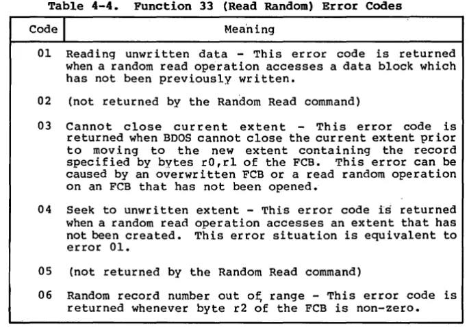
READ RANDOM
,'---~
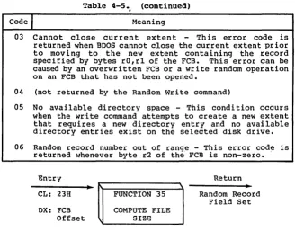
The Read Random function is similar to the sequential file read operation of previous releases, except that the read operation takes place at a.particular record number, selected by the 24-bit value constructed from the three byte field following the FCB (byte positions r'O at 33, rl at 34, and r2 at 35). Note that the sequence of 24 bits is stored with least significant byte first (rO), middle byte next (rl), and high byte last (r2). CP/M does not reference byte r2, exce~t in computing the size of a file (function 35). Byte r2 must be zero, however, since a non-zero value indicates overflow past the end of file.
Thus, the rO, rl byte pa ir is treated as a double-byte, or "word" value, which contains the record .to read. This value ranges from 0 to 65535, providing access to any particular record of any size file. In order to access a file using the Read Random 'function, the base extent (extent 0) must first be opened. Although the base extent mayor may not contain any allocated data, this ensures that the FCB is properly initialized for subsequent random access operations. The selected record number is then stored into the random record field (rO,rl), and the BOOS is called to read the record. Upon return from the call, register AL either contains an error code, as listed below, or the value, 00 indicating the operation was successful. In the latter case, the buffer at the current DMA address contains the randomly accessed record. Note that contrary to the sequential read operation, the record number is not advanced. Thus, subsequent random read operations continue to read the same record.