M A R C H 1 9 9 4
WRL
Research Report 94/3
Complexity/Performance
Tradeoffs with
Non-Blocking Loads
research relevant to the design and application of high performance scientific computers. We test our ideas by designing, building, and using real systems. The systems we build are research prototypes; they are not intended to become products.
There is a second research laboratory located in Palo Alto, the Systems Research Cen-ter (SRC). Other Digital research groups are located in Paris (PRL) and in Cambridge, Massachusetts (CRL).
Our research is directed towards mainstream high-performance computer systems. Our prototypes are intended to foreshadow the future computing environments used by many Digital customers. The long-term goal of WRL is to aid and accelerate the development of high-performance uni- and multi-processors. The research projects within WRL will address various aspects of high-performance computing.
We believe that significant advances in computer systems do not come from any single technological advance. Technologies, both hardware and software, do not all advance at the same pace. System design is the art of composing systems which use each level of technology in an appropriate balance. A major advance in overall system performance will require reexamination of all aspects of the system.
We do work in the design, fabrication and packaging of hardware; language processing and scaling issues in system software design; and the exploration of new applications areas that are opening up with the advent of higher performance systems. Researchers at WRL cooperate closely and move freely among the various levels of system design. This allows us to explore a wide range of tradeoffs to meet system goals.
We publish the results of our work in a variety of journals, conferences, research reports, and technical notes. This document is a research report. Research reports are normally accounts of completed research and may include material from earlier technical notes. We use technical notes for rapid distribution of technical material; usually this represents research in progress.
Research reports and technical notes may be ordered from us. You may mail your order to:
Technical Report Distribution
DEC Western Research Laboratory, WRL-2 250 University Avenue
Palo Alto, California 94301 USA
Reports and notes may also be ordered by electronic mail. Use one of the following addresses:
Digital E-net: JOVE::WRL-TECHREPORTS
Internet: [email protected]
UUCP: decpa!wrl-techreports
Complexity/Performance Tradeoffs with
Non-Blocking Loads
Keith I. Farkas and Norman P. Jouppi
March, 1994
Abstract
Non-blocking loads are a very effective technique for tolerating the cache-miss latency on data cache references. We describe several methods for implementing non-blocking loads. A range of resulting hardware complexity/performance tradeoffs are investigated using an object-code translation and instrumentation system. We have investigated the SPEC92 benchmarks and have found that for the integer benchmarks, a simple hit-under-miss implementation achieves almost all of the available performance improvement for relatively little cost. However, for most of the numeric benchmarks, more expensive implementations are worthwhile. The results also point out the importance of using a compiler capable of scheduling load instructions for cache misses rather than cache hits in non-blocking systems.
Table of Contents
1. Introduction 1
2. Hardware Options 2
2.1. Implicitly Addressed MSHRs 2
2.2. Explicitly Addressed MSHRs 3
2.3. In-Cache MSHR Storage 4
2.4. Inverted MSHR Organization 4
2.5. Hardware Summary 6
3. Simulation Methodology 6
3.1. Processor and Memory Models 6
3.2. Simulation Framework 7
3.3. Methodology 8
4. Baseline Performance Investigations 9
4.1. Implicit vs. Explicit Addressing 16
4.2. In-cache MSHR Storage 16
5. Variations on the Baseline Configuration 17
5.1. Variations in Cache Size 17
5.2. Variations in Cache Line Size 18
5.3. Variations in Miss Penalty 19
6. Applying the Results to Specific Machines 20
7. Conclusions 21
Acknowledgements 22
List of Figures
Figure 1: Basic implicitly addressed MSHR fields 3
Figure 2: Explicitly addressed MSHR fields 4
Figure 3: Inverted MSHR organization 5
Figure 4: Benchmark characteristics; references in millions 8
Figure 5: Baseline miss CPI for doduc 9
Figure 6: Histogram of in-flight misses and fetches for doduc. 11
Figure 7: Stall cycle breakdown for doduc 11
Figure 8: Baseline miss rate for doduc 12
Figure 9: Baseline miss CPI for xlisp 13
Figure 10: Miss CPI for xlisp with a fully associative cache 13
Figure 11: Baseline miss CPI for eqntott 14
Figure 12: Baseline miss CPI for tomcatv 15
Figure 13: Baseline MCPI for 18 SPEC92 benchmarks. 15
Figure 14: Explicit, implicit, and hybrid MSHRs for doduc 16
Figure 15: Baseline miss CPI for su2cor 17
Figure 16: Miss CPI for doduc with a 64KB data cache 18
Figure 17: Miss CPI for doduc with 16 byte lines 19
1. Introduction
A continuing trend in the design of computer systems is the widening gap between microprocessor and memory speeds. This speed discrepancy can significantly impact the perfor-mance obtained from the system if the processor stalls whenever a data-cache miss occurs. To prevent such stalls, non-blocking loads and stores can be provided to allow the processor to con-tinue executing instructions while a data-cache miss is resolved. Using non-blocking instruc-tions with sufficient hardware resources, a data-miss induced stall will only occur if the register target of the load is used by an instruction before the register is filled.
There are two common methods for implementing non-blocking stores. The first method en-tails placing the data to be stored in a write buffer while the cache fetches the line into which the data is to be stored. The second method is to use write policies other than fetch-on-write, such as write-around, which neither fetch data on a write miss nor write the new data into the cache; instead the data is written directly to the next lower level in the memory hierarchy [6]. Both of these methods do not require very complex hardware and are becoming common in microproces-sors.
To allow the processor to continue to access the data cache during the processing of a non-blocking load miss, a lockup-free cache [7] is required. Non-non-blocking loads have only recently appeared in microprocessors [3, 9], and often these implementations have been fairly restrictive. For example, the HP PA7100 [1] allows a maximum of only one miss outstanding in the cache (i.e., ‘‘hit under miss’’). The only recent appearance of mostly restrictive implementations is in part due to the more significant hardware complexity required to implement non-blocking loads. Yet studies of non-blocking loads have often assumed very unrestricted models. For example, Sohi and Franklin [12] assumed an 8-way banked cache where each bank could support four outstanding fetches and several times more misses. Other studies [2, 5, 11] generally have used unrestricted models while focusing on other aspects of system performance.
We investigate the performance obtainable from a number of practical non-blocking load im-plementations and evaluate the performance obtained in the context of the hardware complexity required. Key to our investigation is careful modeling of the processor and memory system and judicious accounting for the complexities involved with non-blocking loads. Our results suggest that a significant portion of the available performance improvement can be achieved with im-plementations that are not nearly as complex as the unrestricted imim-plementations assumed in many previous studies.
2. Hardware Options
To support multiple in-flight (i.e., outstanding) misses, lockup-free caches require special hardware resources which we describe below. In discussing non-blocking loads it is helpful to divide the misses into three categories. The first miss to a cache block with a given tag is called the primary miss [7]. Subsequent misses to any of the bytes in the block that is being fetched may cause a stall depending on the hardware resources available. If a stall occurs due to such a structural hazard, the miss causing the stall is called a structural-stall miss. If, however, a structural-hazard-induced stall is not required, then the miss is referred to as a secondary miss
[7]. Secondary misses require in-flight-miss resources while structural-stall misses do not.
The organization of a lockup-free cache with support for non-blocking loads was first given by Kroft [7]. In Kroft’s implementation, registers called MSHRs (Miss Status Holding Registers) are used to hold information on outstanding misses. The MSHRs save enough infor-mation on a miss so that when a requested cache block arrives from the next lower level in the memory system, load instructions for the corresponding block can be completed. One MSHR is associated with each fetch request outstanding to the next lower level in the memory hierarchy. A primary miss and several secondary misses can be merged into a single fetch request. Kroft’s organization only allows one miss per word in the cache block being fetched. If two misses occur to a word while the block is being fetched, the processor would stall; this second miss is an example of what we call a structural-stall miss. In the remainder of this section we consider four organizations of MSHRs: implicitly addressed, explicitly addressed, in-cache MSHRs, and an inverted MSHR organization.
2.1. Implicitly Addressed MSHRs
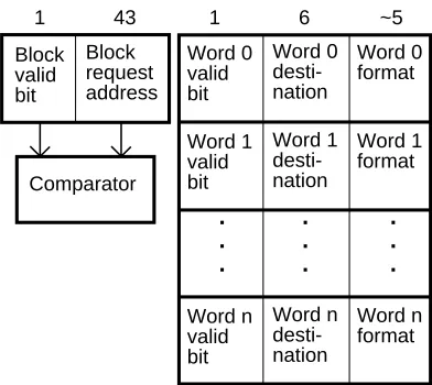
COMPLEXITY/PERFORMANCETRADEOFFS WITHNON-BLOCKINGLOADS Block request address Block valid bit 43 1 Word 0 valid bit 1 Word 0 desti-nation 6 Word 0 format ~5 Word n valid bit Word n desti-nation Word n format . . . Comparator Word 1 valid bit Word 1 desti-nation Word 1 format . . . . . .
Figure 1: Basic implicitly addressed MSHR fields
Note that all lockup-free caches require information to be carried along with returning fetch data in order to match up waiting requests and returning data, unless all data returns in the order it is requested. For example, if there are a small number of MSHRs, the MSHR number might be sent with a fetch request as a tag and then returned with the fetched data. However, since in most systems addresses already need to be sent to the CPU from the memory system for in-validations when maintaining cache consistency, if these addresses are sent with returning fetch data then the MSHRs can be probed with the address of fetch data on its return.
2.2. Explicitly Addressed MSHRs
Even though the basic MSHR of Figure 1 is fairly large ((4×12)+44=92 bits in the example above, plus a 44 bit comparator and significant control logic) it has two limitations. First, mul-tiple accesses to the same word while a fetch of their block is outstanding will cause a stall. Even in a machine with a 64 bit virtual address architecture, there may be a fair number of loads and stores of 32 bit data for many years to come. So instead of providing 64 bit word granularity in the word area, the number of word records may need to be doubled by reducing their granularity to 32 bits. This doubling would increase the number of bits in the word section of our example to 8×12=96 bits, making each MSHR 140 bits wide in total. However, this increase still does not allow multiple byte loads to be outstanding to the same 32 bit word in machines with byte loads and stores. A second limitation is that multiple loads to the exact same address will also cause stalls. Therefore, with this type of MSHR organization it is important for the compiler to combine byte operations into word accesses and to use register moves instead of loading from the same address twice.
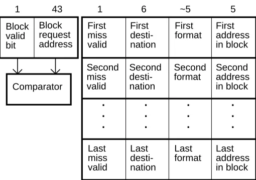
than an implicitly addressed MSHR for 32 byte lines with 4 byte granularity. Explicitly ad-dressed MSHRs work best when there are only a limited number of misses to the same block and these references overlap or are to adjacent bytes or halfwords.
First miss valid First desti-nation First format First address in block 5 Last miss valid Last desti-nation Last format Last address in block Block request address Block valid bit 43
1 1 6 ~5
[image:12.612.161.416.118.298.2]. . . Comparator . . . . . . . . . Second miss valid Second desti-nation Second format Second address in block
Figure 2: Explicitly addressed MSHR fields
2.3. In-Cache MSHR Storage
Implementing a large number of MSHRs each with support for many misses can require large amounts of storage. Franklin and Sohi [4] have observed that cache lines waiting to be filled on outstanding fetches can be used to store MSHR information. This can be done by adding a transit bit to each cache line. This bit indicates that the line is in the process of being fetched, that the address in the cache tag specifies the address being fetched, and that the data in the cache line itself gives MSHR information. Using this technique, many secondary misses could be sup-ported whether the MSHR fields were addressed implicitly or explicitly. However, in direct-mapped caches only one in-flight primary miss per cache set can be supported. One thing to keep in mind with this method is that if the read port width of the cache is much smaller than the line size (e.g., if only 8 bytes of a 32 byte line can be read per cycle), it may take several cycles to read the entire cache line when fetch data arrives. Thus it may be advantageous to limit the length of the MSHR information to the width that can be read in a single cycle. Also, even though only one bit is added to each cache line, for very large caches this may require more area than a simpler distinct set of MSHRs.
2.4. Inverted MSHR Organization
COMPLEXITY/PERFORMANCETRADEOFFS WITHNON-BLOCKINGLOADS
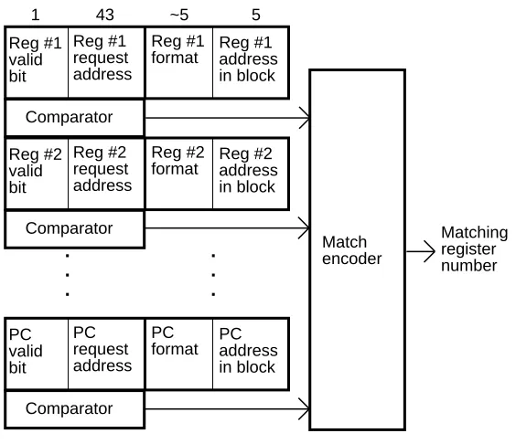
As an alternative organization for an aggressive lockup-free cache, we introduce an inverted MSHR (see Figure 3). In an inverted MSHR there is one set of fields for each possible destina-tion of fetch data, instead of one set of fields for each outstanding fetch as in a tradidestina-tional MSHR organization. The possible destinations of fetch data could include all the integer and floating-point general purpose registers in the machine, write buffer entries (for merging with write data when writing into a write-allocate cache), the program counter, and an instruction prefetch buffer (if it exists). Thus a typical inverted MSHR might have between 65 and 75 entries.
43
1 ~5 5
Reg #2 request address Reg #2 valid bit Reg #2
format Reg #2address in block Comparator PC request address PC valid bit PC
format PCaddress in block Comparator Reg #1 request address Reg #1 valid bit Reg #1
[image:13.612.183.465.175.418.2]format Reg #1address in block Comparator . . . . . . Match encoder Matching register number
Figure 3: Inverted MSHR organization
When a new miss occurs, the inverted MSHR is searched associatively just like a traditional set of MSHRs. If there is already an outstanding fetch for that block, one or more matches will occur. In this case, the miss address is not sent off-chip, but the inverted MSHR entry cor-responding to the destination of the fetch data is marked valid and its block request address, formatting information, and address within the block are written. In the event there are no matches, the MSHR entry corresponding to the destination of the fetch data is still written in the same way, but a fetch of the requested block from the next lower level in the memory hierarchy is also begun. When a block of data returns the inverted MSHR must be probed to identify those destinations waiting for data from the block. Then each waiting destination is filled in turn using the information contained in the MSHR. This information specifies the format to be used and indentifies the the portion of the block which is to be loaded into the the destination.
2.5. Hardware Summary
In this section we have described several mechanisms that can be used to store information about outstanding misses. Many other mechanisms would be possible. We have attempted to list the simplest mechanisms covering a spectrum of non-blocking support. In the following sections we present simulation results that could be expected when using different non-blocking hardware support.
3. Simulation Methodology
The performance achieved with the lockup-free implementations described in the previous section is a function of the number of in-flight misses that are supported. To evaluate the com-plexity versus performance tradeoff for these implementations, we investigated the performance achieved when restrictions are imposed on the number and the type of in-flight misses. For this investigation, we chose models for the processor and the memory system that isolate the mance available from various non-blocking organizations from other aspects of machine perfor-mance. This isolation is achieved by structuring the models so that all processor stalls only relate to data accesses. As a result, performance is measure using the average number of memory stall cycles per instruction (CPI). In Section 6, we describe how the results can be extended to systems with more complex processors and memories.
3.1. Processor and Memory Models
The processor model we use has separate data and instruction caches, a multistage pipeline and 3 operand instructions. Since we are only concerned with the behavior of the data cache, all instructions are assumed to hit in the instruction cache. Branch instructions may also introduce stalls if the branch-delay slot(s) cannot be filled by the compiler or if the branch is taken. Branch stalls may occur at the same time as other stalls such as those attributable to accessing a register before its contents are valid. Therefore, to take branch stalls into account requires explicitly modeling them. In addition, the length of a stall is determined by cache hit rates, memory access delays and code scheduling. To avoid having to model a complex memory system and thereby render our results less general, we avoid branch induced stalls by assuming that there are no branch delay slots and that there is a perfect branch-target predictor.
To remove the effects of stalls caused by resource conflicts, we have chosen to model a single-issue processor with single cycle instruction latencies. The register file comprises 32 integer and 32 floating point registers that can be accessed via 2 read and multiple write ports; the need for multiple write ports is explained below.
COMPLEXITY/PERFORMANCETRADEOFFS WITHNON-BLOCKINGLOADS
all registers waiting for the data are updated at the same time; that is, all primary, structural-stall, and secondary misses for a block are simultaneously resolved. This assumption necessitates multiple write ports for the register file.
Given the above assumptions, a stall will only occur if there are too many cache misses out-standing (i.e., a structural-hazard, miss-induced stall) or if a use is made of a register before a previously issued load completes (i.e., a true data dependency, miss-induced stall). As all stalls concern misses, the term miss CPI (MCPI) will be used in lieu of memory stall CPI.
3.2. Simulation Framework
To perform the simulations for this study, we used an object-code translation and instrumen-tation system. This system emulates the execution of a benchmark as it would run on a target machine by running the benchmark on an existing machine. As a result both the functional be-havior and the memory bebe-havior of the application are simulated. The first step in performing a simulation is to compile the benchmark using instruction scheduling rules pertaining to the ar-chitecture of the processor to be modeled. We use a modified version of the Multiflow VLIW
1
Compiler [8] for this purpose . Next, the resulting assembly language (i.e., object code) is trans-lated into the assembly language of the machine on which the simulations are run, namely, Alpha AXP workstations. Instrumentation and modeling code is then inserted into the translated code. Finally, the augmented, translated binary is linked with run-time libraries and support routines. The run-time libraries contain routines (e.g., sin()) that are called from within the benchmark and as such their execution must also be emulated. Hence, these routines have been compiled and instrumented in the same manner as the benchmark.
The instrumentation code is inserted to record the emulated run-time behavior of the benchmark. This code records various statistics including cache miss rates, the number of (simu-lated) instructions executed, and the number of (simu(simu-lated) clock cycles. The modeling code is inserted to allow the factoring in of the time required to resolve memory and register accesses. This modeling is accomplished by inserting before every emulated load and store instruction a call to a procedure that models the memory. These calls pass to the procedure the address of the item being loaded or stored and the procedure returns the amount of time required to process the access. For example, for non-blocking loads, this time will be the time required to launch the load whereas for a blocking-load it will be the time required to load the data into the cache if it is missing. A mechanism in the simulator adjusts these addresses so that they do not reflect the presence of the simulation infrastructure. Calls to a scoreboard procedure are also inserted be-fore every emulated instruction that uses the result of a load. This procedure factors in the time required to validate the source registers of the instruction.
1The compiler was modified to produce RISC-like object code for a processor with 32 bit addresses, 32 bit
3.3. Methodology
To explore the performance of the various implementations, the following software and hardware parameters were varied:
1. load latency: The load latency is the time in cycles that the compiler assumes is required to fetch data from the cache on a cache hit and load it into a register. This parameter indicates to the compiler how many instructions it should try to insert between the load instruction and the first use. In contrast, the simulator always uses a cache hit load latency of 1. Thus the (scheduled) load latency parameter gives the degree of cache miss tolerance that is expected if the compiler success-fully scheduled the code for this latency. It is important to note that the load latency is a code-scheduling parameter and not a system parameter.
2. in-flight misses: Both the number of primary and secondary misses permitted to be outstanding to each set in the cache, and the number of primary and secondary misses permitted to be outstanding to the cache as a whole.
3. cache parameters: The cache size and the line size.
4. miss penalty: The miss penalty is the time in cycles required to fill a line in the cache from the next-lower level in the memory hierarchy.
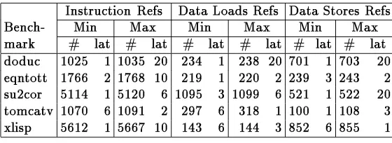
We have simulated 18 of the SPEC92 benchmarks for a wide range of the above parameters. The results we present below represent over 3700 simulations requiring approximately 370 days of run-time. This paper discusses in detail five representative benchmarks of the 18; these five are listed in Table 4 along with some run-time characteristics. The three major columns give breakdowns based on instruction, load, and store references. The sub-columns give information about the load latency parameters which resulted in the minimum and maximum number of in-structions executed. Individual columns give the number of inin-structions executed (in millions) and the load latency for which this maximum or minimum number of instructions was executed.
[image:16.612.147.427.477.579.2]Instruction Refs Data Loads Refs Data Stores Refs
Bench-
Min
Max
Min
Max
Min
Max
mark
# lat # lat # lat # lat # lat # lat
doduc 1025 1 1035 20 234 1 238 20 701 1 703 20
eqntott 1766 2 1768 10 219 1 220 2 239 3 243 2
su2cor 5114 1 5120 6 1095 3 1099 6 521 1 522 20
tomcatv 1070 6 1091 2 297 6 318 1 100 1 108 3
xlisp
5612 1 5667 10 143 6 144 3 852 6 855 1
Figure 4: Benchmark characteristics; references in millions
COMPLEXITY/PERFORMANCETRADEOFFS WITHNON-BLOCKINGLOADS
Note that the references presented in the table do not include those generated by the operating system as we could not instrument operating system routines.
4. Baseline Performance Investigations
In this section, we explore the performance and the cost effectiveness of non-blocking load implementations for our baseline cache configuration of a 8 Kbyte direct mapped cache with 32 byte lines and a 16 cycle miss penalty. In the ensuing discussion, it is important to remember that the only stalls that can occur are those attributable to true data dependencies or structural hazards.
We begin with doduc which best illustrates many of the characteristics common to all benchmarks. The MCPI incurred by doduc with several of the simpler non-blocking implemen-tations is shown in Figure 5. In this figure, each curve corresponds to a specific cache im-plementation and the curves show how the MCPI varies with the scheduled load latency. The upper two curves correspond to lockup caches and are given for sake of comparison. These curves have labels that include the term ‘‘mc=0’’. This term indicates that the implementations allow zero outstanding misses to a cache without stalling the processor, or in other words, are lockup. The term ‘‘+wma’’ included in the label of the upper-most curve indicates that in ad-dition to being lockup, the cache used write-miss allocate, and the processor stalls until misses caused by writes have been serviced. The bottom-most curve, labeled ‘‘no restrict’’ shows the MCPI incurred with a lockup-free cache using an inverted MSHR. The other curves correspond to more restricted and lower cost lockup-free implementations.
mc=0 + wma mc=0 mc=1 fc=1 mc=2 fc=2 no restrict
0 2 4 6 8 10 12 14 16 18 20
0.05 0.1 0.15 0.2 0.25 0.3 0.35 0.4 0.45 0.5 0.55
load latency
[image:17.612.162.487.402.674.2]miss CPI
The curve labeled ‘‘mc=1’’ (one outstanding miss to the cache) corresponds to a hit-under-miss scheme implemented using a single MSHR with one explicitly addressed field. A simple modification to this scheme is to employ an additional MSHR with only one destination address; this scheme allows two in-flight misses, one or both of which can be primary misses. The MCPI for this scheme is given by the curve ‘‘mc=2’’. To support multiple secondary misses but only one fetch operation, the hit-under-miss hardware could be replaced with a single explicitly-addressed MSHR with many destination addresses. The MCPI incurred with this implemen-tation is given by the curve labeled ‘‘fc=1’’ (one fetch outstanding to a cache), since one primary miss and many secondary misses can be outstanding, but they must all be satisfied by the same cache line refill. For now we assume an infinite number of fields in the MSHR thereby support-ing an unlimited number of secondary misses; we will consider the effects from limitsupport-ing the number later. The final curve corresponds to an implementation with two such MSHRs and is the most complex of the restricted implementations.
Note that all the lockup-free implementations achieve very similar MCPIs for a load latency of 1. This fact, as will be discussed below, is a consequence of the algorithm used to schedule the code. The lockup-free implementations, however, achieve different MCPIs for load latencies bigger than the cache-hit latency. The simplest, hit-under-miss, incurs 2.9 times the MCPI of the unrestricted cache for a scheduled load latency of 10. If the hit-under-two-miss scheme is employed, this factor drops to 1.7, a significant improvement yet one which incurs little ad-ditional hardware complexity.
Consider the relative position of the ‘‘fc=1’’ and ‘‘mc=2’’ curves. This ordering indicates that doduc benefits more from allowing two primary misses to be in-flight than from allowing un-limited secondary misses to a single block being fetched. This fact is true for many of the other benchmarks. Finally, if the ‘‘fc=2’’ implementation was used instead, the MCPI incurred would be only 1.3 times the MCPI of the unrestricted implementation.
The curves in Figure 5 show two peculiarities that are attributable to the load latency. The first concerns the similar performance at a load latency of 1. With a load latency of 1, the com-piler often schedules the instruction that uses the target register of a load immediately after the load instruction. Hence, it is rare for there to be more than one outstanding load and thus there is little to differentiate the lockup-free implementations. For doduc, we can compute the percent of the run-time that there is more than one miss outstanding from the numbers in Figure 6. This figure presents the in-flight miss and in-flight fetch histograms for doduc for each load latency and for a 16 cycle miss penalty. For a load latency of 1, there is at least one in-flight miss 27% of the time (the column labeled MIF), while for 92% of this time, there is only one miss. Thus for only 27%×(100%−92%) = 2% of the run-time is there more than a single miss outstanding.
COMPLEXITY/PERFORMANCETRADEOFFS WITHNON-BLOCKINGLOADS
load % time with in-ight % of MIF for # in ight
lat-
>0misses in
1 2 3 4 5 6 7+ max #
ency ight (MIF)
1
27
misses 92 8 0 0 0 0
0
12
fetches 95 5 0 0 0 0
0
5
2
25
misses 69 18 5 4 2 1
1
16
fetches 80 14 3 1 1 1
0
13
3
27
misses 64 20 6 5 1 1
3
16
fetches 80 15 3 1 1 0
0
14
6
22
misses 54 25 9 6 2 1
3
16
fetches 75 18 4 2 1 0
0
13
10
22
misses 51 23 10 9 3 1
3
16
fetches 70 20 6 2 1 1
0
14
20
26
misses 53 22 10 8 3 1
3
16
[image:19.612.181.468.69.266.2]fetches 73 18 5 2 2 0
0
14
Figure 6: Histogram of in-flight misses and fetches for doduc.
Because the compiler tries to increase the distance between the load and the first instruction to use its result, with longer load latencies there will be a decrease in true-data dependency stalls and a possible increase in the number of structural hazard stalls. This tradeoff is illustrated in Figure 7 which shows the portion of the MCPI that is attributable to structural-hazard induced stalls. This percentage is higher for longer load latencies. Note that when a compiler schedules for a load hit on a machine that can issue multiple instructions per cycle and has a cache-hit latency longer than one cycle, the compiler is already scheduling for load latencies greater than one. (More details on scaling our results to multi-issue machines is given in Section 6.)
mc=0 + wma mc=0 mc=1 fc=1 mc=2 fc=2 no restrict
0 2 4 6 8 10 12 14 16 18 20
0 2 4 6 8 10 12 14 16
load latency
[image:19.612.159.490.417.694.2]% MCPI due to structural hazard stalls
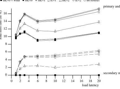
The second peculiarity concerns the dip in the MCPIs that occurs at a load latency of 6. This dip occurs mainly because the primary and secondary cache miss rate also decreases at this value. This decrease is shown in Figure 8 which gives the combined primary and secondary miss rate as well as the secondary miss rate for the various implementations. The rate changes are attributable to the instruction movement and the grouping of load instructions which the compiler performs when trying to schedule for longer load latencies. When several misses are scheduled in close proximity, it is possible that some of these will access data that maps to the same line in the cache. Hence, while the compiler is trying to schedule the code to better tolerate cache misses, the conflict-miss rate may increase. The dip seen at a load latency of 6 cor-responds to a code schedule that contains fewer conflict misses. Such discontinuities also exist with many of the other benchmarks.
mc=0 + wma mc=0 mc=1 fc=1 mc=2 fc=2 no restrict
primary and secondary misses
secondary misses
0 2 4 6 8 10 12 14 16 18 20
0 2 4 6 8 10 12 14 16
load latency
[image:20.612.55.442.240.525.2]load miss rate (in %)
Figure 8: Baseline miss rate for doduc
COMPLEXITY/PERFORMANCETRADEOFFS WITHNON-BLOCKINGLOADS
mc=0 + wma mc=0 mc=1 fc=1 mc=2 fc=2 no restrict
0 2 4 6 8 10 12 14 16 18 20
0.14 0.15 0.16 0.17 0.18 0.19 0.2 0.21 0.22 0.23 0.24 0.25 0.26 0.27
load latency
[image:21.612.161.488.71.345.2]miss CPI
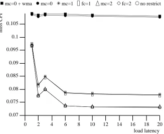
Figure 9: Baseline miss CPI for xlisp
mc=0 + wma mc=0 mc=1 fc=1 mc=2 fc=2 no restrict
0 2 4 6 8 10 12 14 16 18 20
0.07 0.072 0.074 0.076 0.078 0.08 0.082 0.084 0.086 0.088 0.09
load latency
[image:21.612.161.488.370.641.2]miss CPI
Figure 10: Miss CPI for xlisp with a fully associative cache
by true data dependency stalls; structural hazard induced stalls account for less than 1% of the MCPI. The discontinuity at a load latency of 3 is another manifestation of the effect that produces the dip at a load latency of 2 for xlisp.
mc=0 + wma mc=0 mc=1 fc=1 mc=2 fc=2 no restrict
0 2 4 6 8 10 12 14 16 18 20
0.07 0.075 0.08 0.085 0.09 0.095 0.1 0.105
load latency
[image:22.612.127.454.122.389.2]miss CPI
Figure 11: Baseline miss CPI for eqntott
As shown in Figure 12, the tomcatv benchmark incurs MCPI values that are an order of mag-nitude larger than those incurred by eqntott. The relative ordering of the curves for the various implementations is the same as those for the benchmarks presented above. Unlike doduc, however, tomcatv incurs an almost constant MCPI for load latencies 6 and larger. Tomcatv con-tains two nested loops which are unrolled many times by the compiler, and for load latencies of 6 and larger, the resulting code schedules are nearly identical. The performance for tomcatv as the load latency is varied corresponds to what intuition suggests would occur, namely, the MCPI monatomically decreases and the rate of decrease is smaller as the load latency becomes larger. This intuitive behavior is usually not exhibited by the other benchmarks, due to changes in the in-flight load profile brought about by changes in the load latency.
COMPLEXITY/PERFORMANCETRADEOFFS WITHNON-BLOCKINGLOADS
mc=0 + wma mc=0 mc=1 fc=1 mc=2 fc=2 no restrict
0 2 4 6 8 10 12 14 16 18 20
0 0.2 0.4 0.6 0.8 1 1.2 1.4 1.6 1.8
load latency
[image:23.612.160.488.73.344.2]miss CPI
Figure 12: Baseline miss CPI for tomcatv
mc=0
mc=1
mc=2
fc=1
fc=2
1mcpi
mcpi
mcpi
mcpi
mcpi
mcpi
alvinn
0.494 1.4 0.398 1.1 0.371 1.0 0.394 1.1 0.367 1.0 0.365
doduc
0.346 4.1 0.245 2.9 0.147 1.7 0.197 2.4 0.109 1.3 0.084
ear
0.094 2.0 0.067 1.5 0.050 1.1 0.067 1.5 0.050 1.1 0.048
fpppp
0.434 7.1 0.234 3.8 0.119 1.9 0.197 3.2 0.091 1.5 0.062
hydro2d 0.708 3.7 0.466 2.5 0.246 1.3 0.457 2.4 0.242 1.3 0.189
mdljdp2 0.314 1.9 0.231 1.4 0.193 1.2 0.227 1.4 0.190 1.1 0.167
mdljsp2 0.154 3.4 0.088 1.9 0.057 1.2 0.070 1.5 0.052 1.1 0.046
nasa7
1.865 3.6 1.452 2.8 0.753 1.5 1.360 2.6 0.670 1.3 0.519
ora
1.000 1.0 1.000 1.0 1.000 1.0 1.000 1.0 1.000 1.0 1.000
su2cor 1.266 14 1.055 11 0.437 4.7 1.002 10 0.394 4.2 0.093
swm256 0.297 4.4 0.110 1.6 0.070 1.0 0.109 1.6 0.069 1.0 0.067
spice2g6 1.092 1.2 0.958 1.1 0.903 1.0 0.945 1.1 0.896 1.0 0.891
tomcatv 1.140 17 0.714 11 0.310 4.7 0.649 9.8 0.219 3.3 0.066
wave5
0.277 2.6 0.194 1.8 0.132 1.2 0.183 1.7 0.126 1.2 0.107
compress 0.453 1.3 0.354 1.0 0.349 1.0 0.351 1.0 0.348 1.0 0.348
eqntott 0.108 1.5 0.078 1.1 0.073 1.0 0.078 1.1 0.073 1.0 0.073
espresso 0.209 1.2 0.176 1.0 0.170 1.0 0.174 1.0 0.170 1.0 0.169
xlisp
0.211 1.2 0.185 1.1 0.176 1.0 0.181 1.0 0.176 1.0 0.176
[image:23.612.159.485.374.631.2]4.1. Implicit vs. Explicit Addressing
In the MCPI figures shown above, the curves labeled ‘‘fc=1’’ and ‘‘fc=2’’ correspond to lockup-free caches supporting an infinite number of in-flight secondary misses. However, im-plicitly addressed MSHRs limit the number of outstanding misses to one per sub-block where a sub-block is the number of bytes of the cache line for which there is one destination tag. On the other hand, explicitly-addressed MSHRs allow several misses per sub-block, but have only one sub-block per line. Simulations of doduc and tomcatv were performed to investigate the perfor-mance tradeoffs between these two types of MSHRs; simulations of eqntott and xlisp were not undertaken as both of these incur near optimal MCPI values with the hit-under-miss implemen-tation. Figure 14 presents the results of the simulations for doduc. This table gives the MCPI incurred and the ratio of the MCPI to that of the unrestricted cache for several implementations of the baseline cache and a scheduled load latency of 10; the MCPI for the unrestricted cache is given in the row marked by the symbol for infinity. The first column in the table corresponds to a cache using an implicitly-addressed MSHR whereas the first row corresponds to the use of an explicitly-addressed MSHR; non-edge entries correspond to a hybrid of these two.
number
misses per sub-block
of
1
2
4
sub-blocks MCPI ratio MCPI ratio MCPI ratio
1
0.150 1.79 0.114 1.36 0.085 1.01
2
0.144 1.72 0.086 1.03
4
0.091 1.09
8
0.084 1.00
[image:24.612.147.429.298.400.2]1
0.084 1.00
Figure 14: Explicit, implicit, and hybrid MSHRs for doduc
As can be seen in Figure 14, doduc incurs a MCPI within 1% of the unrestricted cache for caches employing either an explicitly-addressed MSHR with 4 misses per line, or an implicitly-addressed MSHR with 8 sub-blocks per line. This 8 sub-block per line granularity corresponds to an entry for every 4 bytes of the cache line. Using the hardware configurations given in Figures 1 and 2, the hardware costs for a MSHR using 8 implicit addresses is 44+(8×12)=140 bits plus a comparator and control logic. For the 4-entry explicitly addressed MSHR, it is 44+(4×17)=112 bits plus a comparator and control logic. The hybrid approach given in the table (sub-blocks=2, misses=2) offers slightly worse performance but at a cost of 44+(4×16)=106 bits plus a comparator and control logic. (The hybrid organization needs one less address bit in its "address in block" field because it is supplied by the implicit subblock location.)
4.2. In-cache MSHR Storage
COMPLEXITY/PERFORMANCETRADEOFFS WITHNON-BLOCKINGLOADS
this figure, the curves labeled ‘‘fs=’’ correspond to lockup-free implementations that support the specified number of in-flight fetches to a cache set. Thus, for our baseline system with an 8KB data cache and 32 byte line size, ‘‘fs=1’’ would allow up to 256 fetches outstanding, but only one per set in the cache. For a load latency of 10, allowing one fetch per set incurs 2.3 times the MCPI of the unrestricted non-blocking implementation whereas two fetches per set incurs 1.3 times the MCPI. It is clearly advantageous to support multiple fetches per cache set for su2cor. By implementing the in-cache MSHR storage method in a set-associative cache, more than one fetch per set could be in progress simultaneously. However, by implementing a set-associative cache, most of these concurrent conflict misses might be eliminated in the first place.
fs=1 fs=2 mc=0 + wma mc=0 mc=1 fc=1 mc=2 fc=2 no restrict
0 2 4 6 8 10 12 14 16 18 20
0 0.2 0.4 0.6 0.8 1 1.2 1.4 1.6
load latency
[image:25.612.160.491.207.480.2]miss CPI
Figure 15: Baseline miss CPI for su2cor
5. Variations on the Baseline Configuration
In this section we consider the effects of variations in cache size, cache line size, and miss penalty over the baseline cache configuration performance.
5.1. Variations in Cache Size
Figure 16 shows the simulation results for doduc with a 64KB cache with 32 byte lines and 16 cycle miss penalty. Although the miss CPI has been reduced by about a factor of five in com-parison to the results for 8KB caches in Figure 5, the graphs look remarkably similar. This observation indicates that there is still about the same percentage of misses that can be over-lapped, even if the total number of misses has been much reduced. Thus, although the absolute performance improvement due to each non-blocking load organization is about a factor of five smaller, more aggressive organizations still provide additional benefits over simpler organiza-tions.
mc=0 + wma mc=0 mc=1 fc=1 mc=2 fc=2 no restrict
0 2 4 6 8 10 12 14 16 18 20
0.01 0.02 0.03 0.04 0.05 0.06 0.07 0.08 0.09
load latency
miss CPI
Figure 16: Miss CPI for doduc with a 64KB data cache
We have also looked at the performance of the other benchmarks with 64KB caches. In general the overall shape of the graphs for the other benchmarks are also similar to those for 8KB caches, although the absolute miss CPIs may be much lower. We have not looked at cache sizes larger than 64KB, since we are limiting our studies to first-level cache configurations which are feasible for on-chip implementation.
5.2. Variations in Cache Line Size
COMPLEXITY/PERFORMANCETRADEOFFS WITHNON-BLOCKINGLOADS
For our comparisons we assumed a pipelined memory system with 14 cycles for the return of the first 16 bytes on a miss and 2 cycles per additional 16 bytes. Thus the miss penalty for systems with 16 byte lines was 14 cycles, and the miss penalty for systems with 32 byte lines was 16 cycles. Figure 17 shows the miss CPI for doduc with a 16 byte line size. Some dif-ferences can be seen between this figure and Figure 5, which uses 32 byte lines. First, the miss CPI increases slightly for all configurations using 16 byte lines because the 32 byte line size is a better choice given the pipelined memory system. However, the absolute values of the CPI should be ignored for the purposes of this comparison. Instead, looking at the relative perfor-mance of ‘‘mc=1’’, ‘‘mc=2’’, and ‘‘fc=1’’, in Figure 5, the ‘‘fc=1’’ case is about midway be-tween the ‘‘mc=1’’ and ‘‘mc=2’’ cases. If 16 byte lines are used (Figure 17), the miss CPI incurred by ‘‘fc=1’’ moves closer to ‘‘mc=1’’ than ‘‘mc=2’’ (i.e., gets relatively worse). This is to be expected since the cache lines are smaller, so the benefit from supporting an unlimited number of secondary misses to a given cache line is less. In the limit as the cache line size is reduced to a single word, the ‘‘fc=1’’ organization will have the same miss CPI as the ‘‘mc=1’’ organization. We have seen this curve-movement effect when simulating the other benchmarks as well.
mc=0 + wma mc=0 mc=1 fc=1 mc=2 fc=2 no restrict
0 2 4 6 8 10 12 14 16 18 20
0.05 0.1 0.15 0.2 0.25 0.3 0.35 0.4 0.45 0.5 0.55
load latency
[image:27.612.162.485.302.574.2]miss CPI
Figure 17: Miss CPI for doduc with 16 byte lines
5.3. Variations in Miss Penalty
in-crease both the likelihood and the length of true-data-dependency stalls, while shorter latencies decrease both. To illustrate how the miss penalty affects the MCPI, we shall present some data for tomcatv which best illustrates the changes. Table 18 gives the miss CPI when using a scheduled load latency of 10 cycles. (Scheduling for load latencies greater than 10 has little effect, as Figure 12 shows.) The important thing to note is that for non-blocking organizations, the increase in miss CPI when moving from a small miss penalty to a large miss penalty is highly non-linear. This is especially true for the most aggressive implementations. For small miss penalties, virtually all of the miss penalty can be overlapped with computation, so the miss CPI remains very small. As the miss penalty is increased to large values, a higher and higher per-centage of each miss penalty increase directly affects the miss CPI because the amount of pos-sible overlap between misses and computation becomes exhausted. For example, for the un-restricted case when moving from a miss penalty of 16 cycles to 32 cycles (a factor of 2 in-crease), the miss CPI increases by almost a factor of five. In contrast, the blocking organization’s (mc=0) miss CPI is strictly a linear function of the miss penalty.
miss penalty
4
8
16
32
64
128
mc=0+wma 0.483 0.967 1.934 3.868 7.736 15.472
mc=0
0.285 0.570 1.140 2.280 4.561 9.122
mc=1
0.127 0.300 0.714 1.596 3.494 7.469
fc=1
0.111 0.258 0.649 1.511 3.408 7.381
mc=2
0.030 0.097 0.310 0.803 1.939 4.376
fc=2
0.021 0.069 0.219 0.641 1.676 3.866
[image:28.612.147.429.275.393.2]no restrict
0.001 0.013 0.066 0.300 0.928 2.226
Figure 18: MCPI as a function of the miss penalty for tomcatv.
6. Applying the Results to Specific Machines
The processor and memory models we employ (see Section 3.1) were chosen to isolate the performance obtainable with non-blocking hardware from other machine-specific issues. It is possible to interpret our results in the context of specific machines by scaling the input parameters and adjusting the resulting CPI.
COMPLEXITY/PERFORMANCETRADEOFFS WITHNON-BLOCKINGLOADS
To interpret the results for superscalar machines, the simulation parameters can be scaled based on the average number of instructions issued per cycle (IPC) in the superscalar machine. The miss penalties of the superscalar machine should be multiplied by the average IPC of the superscalar machine to get the miss penalties corresponding to this study. Similarly, the latencies for which loads are scheduled for the superscalar machine should be multiplied by the average IPC to get load latencies corresponding to our results. Then the results we have presented for the scaled miss penalty and load latency can be used as a first-order approximation for the MCPI for the multi-issue machine.
To gauge the accuracy of this scaling, we compared simulations of the 18 benchmarks on a dual-issue machine to those on a single-issue machine. This comparison was performed by first simulating the execution of each benchmark on the dual-issue machine using a load latency of 10 and a miss penalty of 16. These parameters were then scaled using the average IPC for each benchmark and a single-issue machine simulation was done using the new parameters. Because it was not convenient to compile the code for all values of the load latency, we used the load latency from the set {1,2,3,6,10,20} that was closest to the scale value; the miss penalty was rounded to the nearest whole number.
The results from this comparison for several of the benchmarks are presented in Table 19 for four non-blocking load implementations. In general, the scaling results in a good first-order approximation. This is especially true when considering the coarseness of the approximation.
IPC scaled
measured dual-issue MCPI and dierence
load miss mc=0 mc=1
fc=2 no rest.
lat. pen.
mcpi%
mcpi%
mcpi%
mcpi%
doduc 1.59 15.9 25.5 0.59 -10 0.50 -7 0.23 -6 0.20 -8
eqntott 1.16 11.7 18.6 0.13 -2 0.10 1 0.09 1 0.09 2
su2cor 1.76 17.6 28.1 2.21 1 2.00 5 0.82 10 0.22 21
tomcatv 1.82 18.2 29.1 2.08 1 1.48 4 0.59 7 0.27 28
xlisp
1.30 13.0 20.9 1.24 -14 1.21 -14 1.20 -14 1.20 -14
[image:29.612.171.480.363.482.2]average 1.53 15.3 24.5 1.25 -5 1.06 -2 0.59 0 0.40 6
Figure 19: Dual and single issue MCPI scaling comparison.
7. Conclusions
We have studied a wide range of techniques for implementing non-blocking loads. These techniques have ranged from organizations that allow only one outstanding miss to organizations which allow as many misses as there are possible load destinations in the machine. Non-blocking loads are a very powerful technique for tolerating cache miss latency. In our baseline system configuration with a 8KB direct-mapped data cache, 32 byte lines, and a 16 cycle miss penalty, non-blocking load implementations can reduce the miss stall CPI of integer benchmarks by up to a factor of two, and can reduce the miss stall CPI of many numeric benchmarks by a factor of 4 to 10.
benchmarks are those that permit several in-flight primary and secondary misses. For some benchmarks, when using a direct-mapped cache it is worthwhile to support multiple misses to different addresses which map to the same cache set.
Surprisingly, we see very similar relative improvements with the addition of non-blocking loads to larger caches. Even though the miss rates may be significantly reduced by using larger caches, the remaining misses are still clustered enough that supporting many simultaneously out-standing misses results in large proportional changes in the miss stall CPI for numeric programs.
As we expected, with 16 byte cache lines rather than 32 byte lines, more benefit is obtained from supporting a greater number of primary misses than secondary misses; the opposite is true for cache lines larger than 32 bytes. Regardless of the cache line size, for lockup-free caches, the miss stall CPI varies non-linearly with the miss penalty.
Finally, our results point out the importance in non-blocking systems of scheduling load in-structions wherever possible for cache misses instead of cache hits. An aggressive compiler that uses trace-scheduling and/or other techniques for increasing instruction-level parallelism is cru-cial to getting enough flexibility to schedule for the longer cache miss latencies.
Acknowledgements
We thank Joel Emer, Bob Nix and David Web for their guidance and answers to numerous questions as we modified and used the simulation infrastructure they developed. We also thank Jeff Mogul, Joel McCormack, Annie Warren and the other WRL-ites for both helping out and putting up with the simulations. Finally, we thank Paul Chow, Corinna Lee, Zvonko Vranesic and the anonymous reviewers for their useful comments.
References
[1] Tom Asprey, et. al. Performance Features of the PA7100 Microprocessor. IEEE Micro 13(3):22-35, June, 1993.
[2] Tien-Fu Chen and Jean-Loup Baer. Reducing Memory Latency via Non-blocking and Prefetching Caches. In Fifth ASPLOS Conference, pages 51-61. October, 1992.
[3] Keith Diefendorf and Michael Allen. Organization of the Motorola 88110 Superscalar RISC Microprocessor. IEEE Micro 12(2):40-63, April, 1992.
[4] Manoj Franklin and Gurindar Sohi. Non-Blocking Caches for High-Performance Processors. Unpublished, 1991.
[5] Kourosh Gharachorloo, Anoop Gupta, and John Hennessy. Hiding Memory Latency using Dynamic Scheduling in Shared-Memory Multiprocessors. In The 19th Intl. Symp. on Computer Architecture, pages 22-33. May, 1992.
[6] Norman P. Jouppi. Cache Write Policies and Performance. In The 20th Intl. Symp. on Computer Architecture, pages 191-201. May, 1993.
COMPLEXITY/PERFORMANCETRADEOFFS WITHNON-BLOCKINGLOADS
[8] P. Geoffrey Lowney et al. The Multiflow Trace Scheduling Compiler. Journal Of Supercomputing 7(1-2):51-142, May, 1993.
[9] Edward McLellan. The Alpha AXP Architecture and 21064 Processor. IEEE Micro 13(3):36-47, June, 1993.
[10] Sunil Mirapuri, Michael Woodacre, and Nader Vasseghi. The MIPS R4000 Processor. IEEE Micro 12(2):pages 10-22, April, 1992.
[11] Anne Rogers and Kai Li. Software Support for Speculative Loads. In Fifth ASPLOS Conference, pages 38-50. October, 1992.
COMPLEXITY/PERFORMANCETRADEOFFS WITHNON-BLOCKINGLOADS
WRL Research Reports
‘‘Titan System Manual.’’ ‘‘The USENET Cookbook: an Experiment in Michael J. K. Nielsen. Electronic Publication.’’
WRL Research Report 86/1, September 1986. Brian K. Reid.
WRL Research Report 87/7, December 1987. ‘‘Global Register Allocation at Link Time.’’
David W. Wall. ‘‘MultiTitan: Four Architecture Papers.’’
WRL Research Report 86/3, October 1986. Norman P. Jouppi, Jeremy Dion, David Boggs, Mich-ael J. K. Nielsen.
‘‘Optimal Finned Heat Sinks.’’ WRL Research Report 87/8, April 1988. William R. Hamburgen.
WRL Research Report 86/4, October 1986. ‘‘Fast Printed Circuit Board Routing.’’ Jeremy Dion.
‘‘The Mahler Experience: Using an Intermediate WRL Research Report 88/1, March 1988. Language as the Machine Description.’’
David W. Wall and Michael L. Powell. ‘‘Compacting Garbage Collection with Ambiguous WRL Research Report 87/1, August 1987. Roots.’’
Joel F. Bartlett.
‘‘The Packet Filter: An Efficient Mechanism for WRL Research Report 88/2, February 1988. User-level Network Code.’’
Jeffrey C. Mogul, Richard F. Rashid, Michael ‘‘The Experimental Literature of The Internet: An
J. Accetta. Annotated Bibliography.’’
WRL Research Report 87/2, November 1987. Jeffrey C. Mogul.
WRL Research Report 88/3, August 1988. ‘‘Fragmentation Considered Harmful.’’
Christopher A. Kent, Jeffrey C. Mogul. ‘‘Measured Capacity of an Ethernet: Myths and WRL Research Report 87/3, December 1987. Reality.’’
David R. Boggs, Jeffrey C. Mogul, Christopher ‘‘Cache Coherence in Distributed Systems.’’ A. Kent.
Christopher A. Kent. WRL Research Report 88/4, September 1988. WRL Research Report 87/4, December 1987.
‘‘Visa Protocols for Controlling Inter-Organizational ‘‘Register Windows vs. Register Allocation.’’ Datagram Flow: Extended Description.’’
David W. Wall. Deborah Estrin, Jeffrey C. Mogul, Gene Tsudik,
WRL Research Report 87/5, December 1987. Kamaljit Anand.
WRL Research Report 88/5, December 1988. ‘‘Editing Graphical Objects Using Procedural
Representations.’’ ‘‘SCHEME->C A Portable Scheme-to-C Compiler.’’
Paul J. Asente. Joel F. Bartlett.
‘‘Optimal Group Distribution in Carry-Skip Ad- ‘‘The Distribution of Instruction-Level and Machine
ders.’’ Parallelism and Its Effect on Performance.’’
Silvio Turrini. Norman P. Jouppi.
WRL Research Report 89/2, February 1989. WRL Research Report 89/13, July 1989.
‘‘Precise Robotic Paste Dot Dispensing.’’ ‘‘Long Address Traces from RISC Machines:
William R. Hamburgen. Generation and Analysis.’’
WRL Research Report 89/3, February 1989. Anita Borg, R.E.Kessler, Georgia Lazana, and David W. Wall.
‘‘Simple and Flexible Datagram Access Controls for WRL Research Report 89/14, September 1989. Unix-based Gateways.’’
Jeffrey C. Mogul. ‘‘Link-Time Code Modification.’’
WRL Research Report 89/4, March 1989. David W. Wall.
WRL Research Report 89/17, September 1989. ‘‘Spritely NFS: Implementation and Performance of
Cache-Consistency Protocols.’’ ‘‘Noise Issues in the ECL Circuit Family.’’ V. Srinivasan and Jeffrey C. Mogul. Jeffrey Y.F. Tang and J. Leon Yang. WRL Research Report 89/5, May 1989. WRL Research Report 90/1, January 1990.
‘‘Available Instruction-Level Parallelism for Super- ‘‘Efficient Generation of Test Patterns Using scalar and Superpipelined Machines.’’ Boolean Satisfiablilty.’’
Norman P. Jouppi and David W. Wall. Tracy Larrabee.
WRL Research Report 89/7, July 1989. WRL Research Report 90/2, February 1990.
‘‘A Unified Vector/Scalar Floating-Point Architec- ‘‘Two Papers on Test Pattern Generation.’’
ture.’’ Tracy Larrabee.
Norman P. Jouppi, Jonathan Bertoni, and David WRL Research Report 90/3, March 1990. W. Wall.
‘‘Virtual Memory vs. The File System.’’ WRL Research Report 89/8, July 1989.
Michael N. Nelson.
‘‘Architectural and Organizational Tradeoffs in the WRL Research Report 90/4, March 1990. Design of the MultiTitan CPU.’’
‘‘Efficient Use of Workstations for Passive Monitor-Norman P. Jouppi.
ing of Local Area Networks.’’ WRL Research Report 89/9, July 1989.
Jeffrey C. Mogul.
‘‘Integration and Packaging Plateaus of Processor WRL Research Report 90/5, July 1990. Performance.’’
‘‘A One-Dimensional Thermal Model for the VAX Norman P. Jouppi.
9000 Multi Chip Units.’’ WRL Research Report 89/10, July 1989.
John S. Fitch.
‘‘A 20-MIPS Sustained 32-bit CMOS Microproces- WRL Research Report 90/6, July 1990. sor with High Ratio of Sustained to Peak
Perfor-‘‘1990 DECWRL/Livermore Magic Release.’’ mance.’’
Robert N. Mayo, Michael H. Arnold, Walter S. Scott, Norman P. Jouppi and Jeffrey Y. F. Tang.
Don Stark, Gordon T. Hamachi. WRL Research Report 89/11, July 1989.
COMPLEXITY/PERFORMANCETRADEOFFS WITHNON-BLOCKINGLOADS
‘‘Pool Boiling Enhancement Techniques for Water at ‘‘Interleaved Fin Thermal Connectors for Multichip
Low Pressure.’’ Modules.’’
Wade R. McGillis, John S. Fitch, William William R. Hamburgen.
R. Hamburgen, Van P. Carey. WRL Research Report 91/9, August 1991. WRL Research Report 90/9, December 1990.
‘‘Experience with a Software-defined Machine Ar-‘‘Writing Fast X Servers for Dumb Color Frame Buf- chitecture.’’
fers.’’ David W. Wall.
Joel McCormack. WRL Research Report 91/10, August 1991.
WRL Research Report 91/1, February 1991.
‘‘Network Locality at the Scale of Processes.’’ ‘‘A Simulation Based Study of TLB Performance.’’ Jeffrey C. Mogul.
J. Bradley Chen, Anita Borg, Norman P. Jouppi. WRL Research Report 91/11, November 1991. WRL Research Report 91/2, November 1991.
‘‘Cache Write Policies and Performance.’’ ‘‘Analysis of Power Supply Networks in VLSI Cir- Norman P. Jouppi.
cuits.’’ WRL Research Report 91/12, December 1991.
Don Stark.
‘‘Packaging a 150 W Bipolar ECL Microprocessor.’’ WRL Research Report 91/3, April 1991.
William R. Hamburgen, John S. Fitch. ‘‘TurboChannel T1 Adapter.’’ WRL Research Report 92/1, March 1992. David Boggs.
‘‘Observing TCP Dynamics in Real Networks.’’ WRL Research Report 91/4, April 1991.
Jeffrey C. Mogul.
‘‘Procedure Merging with Instruction Caches.’’ WRL Research Report 92/2, April 1992. Scott McFarling.
‘‘Systems for Late Code Modification.’’ WRL Research Report 91/5, March 1991.
David W. Wall.
‘‘Don’t Fidget with Widgets, Draw!.’’ WRL Research Report 92/3, May 1992. Joel Bartlett.
‘‘Piecewise Linear Models for Switch-Level Simula-WRL Research Report 91/6, May 1991.
tion.’’ ‘‘Pool Boiling on Small Heat Dissipating Elements in Russell Kao.
Water at Subatmospheric Pressure.’’ WRL Research Report 92/5, September 1992. Wade R. McGillis, John S. Fitch, William
‘‘A Practical System for Intermodule Code Optimiza-R. Hamburgen, Van P. Carey.
tion at Link-Time.’’ WRL Research Report 91/7, June 1991.
Amitabh Srivastava and David W. Wall. ‘‘Incremental, Generational Mostly-Copying Gar- WRL Research Report 92/6, December 1992.
bage Collection in Uncooperative
Environ-‘‘A Smart Frame Buffer.’’ ments.’’
Joel McCormack & Bob McNamara. G. May Yip.
WRL Research Report 93/1, January 1993. WRL Research Report 91/8, June 1991.
‘‘Recovery in Spritely NFS.’’ Jeffrey C. Mogul.
‘‘Tradeoffs in Two-Level On-Chip Caching.’’ ‘‘Boolean Matching for Full-Custom ECL Gates.’’ Norman P. Jouppi & Steven J.E. Wilton. Robert N. Mayo, Herve Touati.
WRL Research Report 93/3, October 1993. WRL Research Report 94/5, April 1994.
‘‘Unreachable Procedures in Object-oriented Programing.’’
Amitabh Srivastava.
WRL Research Report 93/4, August 1993.
‘‘Limits of Instruction-Level Parallelism.’’ David W. Wall.
WRL Research Report 93/6, November 1993.
‘‘Fluoroelastomer Pressure Pad Design for Microelectronic Applications.’’
Alberto Makino, William R. Hamburgen, John S. Fitch.
WRL Research Report 93/7, November 1993.
‘‘A 300MHz 115W 32b Bipolar ECL Microproces-sor.’’
Norman P. Jouppi, Patrick Boyle, Jeremy Dion, Mary Jo Doherty, Alan Eustace, Ramsey Haddad, Robert Mayo, Suresh Menon, Louis Monier, Don Stark, Silvio Turrini, Leon Yang, John Fitch, Wil-liam Hamburgen, Russell Kao, and Richard Swan. WRL Research Report 93/8, December 1993.
‘‘Link-Time Optimization of Address Calculation on a 64-bit Architecture.’’
Amitabh Srivastava, David W. Wall. WRL Research Report 94/1, February 1994.
‘‘ATOM: A System for Building Customized Program Analysis Tools.’’
Amitabh Srivastava, Alan Eustace. WRL Research Report 94/2, March 1994.
‘‘Complexity/Performance Tradeoffs with Non-Blocking Loads.’’
Keith I. Farkas, Norman P. Jouppi. WRL Research Report 94/3, March 1994.
‘‘A Better Update Policy.’’ Jeffrey C. Mogul.
COMPLEXITY/PERFORMANCETRADEOFFS WITHNON-BLOCKINGLOADS
WRL Technical Notes
‘‘TCP/IP PrintServer: Print Server Protocol.’’ ‘‘Boiling Binary Mixtures at Subatmospheric Pres-Brian K. Reid and Christopher A. Kent. sures’’
WRL Technical Note TN-4, September 1988. Wade R. McGillis, John S. Fitch, William R. Hamburgen, Van P. Carey.
‘‘TCP/IP PrintServer: Server Architecture and Im- WRL Technical Note TN-23, January 1992. plementation.’’
Christopher A. Kent. ‘‘A Comparison of Acoustic and Infrared Inspection WRL Technical Note TN-7, November 1988. Techniques for Die Attach’’
John S. Fitch.
‘‘Smart Code, Stupid Memory: A Fast X Server for a WRL Technical Note TN-24, January 1992. Dumb Color Frame Buffer.’’
Joel McCormack. ‘‘TurboChannel Versatec Adapter’’
WRL Technical Note TN-9, September 1989. David Boggs.
WRL Technical Note TN-26, January 1992. ‘‘Why Aren’t Operating Systems Getting Faster As
Fast As Hardware?’’ ‘‘A Recovery Protocol For Spritely NFS’’
John Ousterhout. Jeffrey C. Mogul.
WRL Technical Note TN-11, October 1989. WRL Technical Note TN-27, April 1992.
‘‘Mostly-Copying Garbage Collection Picks Up ‘‘Electrical Evaluation Of The BIPS-0 Package’’ Generations and C++.’’ Patrick D. Boyle.
Joel F. Bartlett. WRL Technical Note TN-29, July 1992. WRL Technical Note TN-12, October 1989.
‘‘Transparent Controls for Interactive Graphics’’ ‘‘The Effect of Context Switches on Cache Perfor- Joel F. Bartlett.
mance.’’ WRL Technical Note TN-30, July 1992.
Jeffrey C. Mogul and Anita Borg.
‘‘Design Tools for BIPS-0’’ WRL Technical Note TN-16, December 1990.
Jeremy Dion & Louis Monier.
‘‘MTOOL: A Method For Detecting Memory Bot- WRL Technical Note TN-32, December 1992. tlenecks.’’
‘‘Link-Time Optimization of Address Calculation on Aaron Goldberg and John Hennessy.
a 64-Bit Architecture’’ WRL Technical Note TN-17, December 1990.
Amitabh Srivastava and David W. Wall. ‘‘Predicting Program Behavior Using Real or Es- WRL Technical Note TN-35, June 1993.
timated Profiles.’’
‘‘Combining Branch Predictors’’ David W. Wall.
Scott McFarling. WRL Technical Note TN-18, December 1990.
WRL Technical Note TN-36, June 1993. ‘‘Cache Replacement with Dynamic Exclusion’’
‘‘Boolean Matching for Full-Custom ECL Gates’’ Scott McFarling.
Robert N. Mayo and Herve Touati. WRL Technical Note TN-22, November 1991.