HONEYWELL
MULTICS
MULTICS
COMMUNICATIONS ADMINISTRATION
SUBJECT
Information Needed by System Administrators for the Management of the Multics Communication System and Communications Channels
SPECIAL INSTRUCTIONS
This publication supersedes the Multics Administrator's Manual -Communications, Order No.: CC75-01, dated July 1982 and its associated addenda, CC75-01A, dated February 1983, and CC75-01B, dated December 1983. Effective with this edition the document is retitled Multics Communications Administration.
Change bars indicate new and changed information; asterisks denote deletions.
See the "Significant Changes" section in the Preface for a description of changed information.
SOFTWARE SUPPORTED
Multics Software Release 11.0
ORDER NUMBER
CC75-02 February 1985
PREFACE
This manual is a guide to the administration of the Multics Communication System. This manual includes information on terminal types, line types, and channel management
The Multics Programmer's Reference Manual, Order No.: AG91, contains general user inf ormation about terminal use and communications input/output Readers of this manual should be familiar with the information in the Programmer's Reference Manual.
Significant Changes in CC75-02
Support for the following hardware features has been discontinued. References have been removed from the documentation.
DATANET 6632
DATANET 355
Advanced Remote Display Station (ARDS) IBM 1050 Model Terminal
IBM 2741 Kodel Terminal Bell 202 ETX Modem Protocol
The FNP must now be configured by means of a prph configuration card (not an FNP card).
The authorization of users allowed to use a communications channel can now be expressed by a range of values (instead of a maximum value only).
A
new
eMFstatement - check_acs - has been
added.A new X.25 TIP parameter - breakall_idle_timer - has been added.
Section 1
Section 2
Section 3
Section 4
Section 5
CONTENTS
Overview of Multics Communication System . . . . Terminals and Channels . . . . FNPs, Controllers, Adapters, and Subchannels Multiplexed Channels . . . . . . . . Channel Names . . . .
Initialization . . . . Consistency of Configuration .
Terminal Types and Line Types . . . . Classification of Communications Channels . . Line Types . . . .
Line Type Assignment . . . . Terminal Types . . . .
Terminal Type Assignment . . . . Modems and Terminal Connections . . . .
Types of Communications Links . . . .
Asynchronous/Synchronous . . . . Full Duplex/Half Duplex . . . . . . . . . Hardwired, Private Line. Dialup . . . . Modems. . . . . . Communications Protocols . . . ... . . .
Examples of Protocols . . . . . . . Automatic Baud Rate Detection . . . .
Lead Control Selection of 1200 Baud . . . . Bit Sampling Selects Other Bauds . . . . Modems . . . . Hardware Flow Control Using the CTS Dataset Lead Channel Master File . . . .
Channel Definition Table . . . . Channel Master File . . . .
Syntax of the CMF . . . . FNP Entries in the CMF . . . . Channel En tries in the CMF . . . . CMF Default Statements . . . . Global Statements Appiicable to all FNPs . . . . Changing Channel Configuration . . . . . . . Sample Channel Master File . . . . . . . Modifying Communications Channels .
Adding Channels . . . .
Deleting Channels . . . . . . . Changing the Status of a Channel . . . .
Section 6
Section 7
attach .. detach ..
remove .
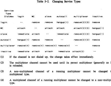
Service Types . . .
FNP and Multiplexer Configuration . . .
F:Nfi Crash Notification FNP Core Images . . . .
Modifying FNP Core Images Using FNP Core Image Required Modules . . . . . Optional Modules . . . . . The Bindfile . . . .
Bindfile Key Words Sample bind_fnp File Commands . . . .
bind_fnp . . . . channel_comm_meters console_report . . . cv_cmf . . . . display_edt . . . . display _fnp_idle fnp_throughput map355 ' . . . . mcs_ version .. . meter_fnp_idle . set_x25_packet_threshold system_comm_meters tty_dump. . . . . . tty_lines . . .
5-3 5-4 5-4 5-4 5-5 5-6 6-1 6-1 6-1 6-2 6-2 6-4 6-4 6-6 7-1 7-2 7-4 7-9 7-12 7-14 7-16 7-18 7-19 7-21 7-22 7-24 7-25 7-27 7-30
Section 8 Subroutines... 8-1
comm_meters_ . . . 8-2
MPX_meters_ .. . . . 8-7
meteringJate_$comm_chan_star_list 8-11
phcs_$get_comm_meters . . . 8-13 Appendix A Directions for Setting Up System-Supplied Multiplexers A-I
Administration and Use of HASP Workstations and Host
Systems . . . . . . A-I
The FNP Core Image A-I
Definition of HASP Channels A -2
Multiplexer Terminal Types . A-3
Subchannel Terminal Types A-5
Control Orders Used by HASP Subchannels A-5 Administration And Use Of IBM3270 Terminals A-6 The FNP Core Image . . . A-7
Definition of IBM3270 Channels A-7
Multiplexer Terminal Types A-8
Subchannel Terminal Types A-9
Typing Conventions . . . A-9 raw3270 h.1ode . . . A-II Administration and Use of Polled VIP Terminals A-II
The FNP Core Image . . . . . . . . A -12 Definition of Polled VIP Channels . . . . . . A -12 Multiplexer Terminal Types . . . . . . . . A-13 Subchannel Terminal Types . . . . . . . . A-15 Input Size Considerations '. . . . . A -15 Function Codes . . . . . . . . A -16 Quits . . . . . . . . A-16 Formfeeds . . . . . . . . A-16 End Of Page . . . . . . . . . A-17 Blank Lines . . . . . . . . A -17 Tabs . . . . . . . . A-17 Circumflex and Tilde . . . . . A -18 Dialups and Hangups . . . . . A -18 Administration and Use of Software-Simulated Terminals . . . . A -18 Definition of Software Terminal Channels . . . . . A-19 Multiplexer Terminal Types . . . A-19 Specifications for and Administration of X.25 Network
Connections . . . . . A -20 Hardware Requirements . . . . . . A-20 Software Support . . . . . . . . A - 20 Link Level (X.25 Level 2) . . . A-20 Packet Level (X.25 Level 3) . . . A-20 Terminal Control Level . . . . . A-21 Implementing an X.25 Capability on Multics . . . A-21 The FNP Core Image . . . . . A -22 Definition of X.25 Channels . . . A-22 Terminal Type File (TIF) . . . A-22 Connecting to a Foreign System Through a Protocol Converter A-25 Channel Definition for Foreign System Connections A-26 Mapping the Terminal Type to the Foreign System A-26
Appendix B Multics Communication System Memory Configurator . B-1 B-1
Appendix C
DN6670 Configured with at least 64K of Memory
Space Requirements in tty _buf . . . . Data Bases in tty _buf . . . . Static Storage in tty_buf . . . . Subchannel and Multiplexer Channel Static Data
Requirements . . . . Calculation of Static Storage in tty _buf . . Dynamic Storage in tty _buf . . . .
Buffer Size When Controlled by Baud Rate Asynchronous I/O Buffer Space . . . . G11S I/O Buffer Space . . . . HASP I/O Buffer Space . . . . IBM2780 and IBM3780 I/O Buffer Space IBM3270 I/O Buffer Space . . . . VIP7760 I/O Buffer Space . . . . X.25 I/O Buffer Space . . . .
Table 3-l. Table 5-l. Table 5-2.
Modem Descriptions . . . Changing Channel Attribuies . Changing Service Types . . . .
vii
Tables
3-5
5-3
5-,5
SECTION 1
OVERVIEW OF l\.1ULTICS C01vll\.1UNICATION SYSTEM
The Multics Communication System effects the transfer of data between the Multics virtual memory and various remote devices (primarily terminals) over communications channels. This manual is concerned with the Multics Communication System as it appears to a system administrator, and it also discusses the specification and management of channels.
*
The bulk of the Multics Communication System resides in the Multics supervisor and in a separate machine, the Front-End Network Processor (FNP). There may be up to eight FNPs on a Multics system. The user-ring and supervisor portions of the Multics Communication System are principally concerned with terminal management, while the primary responsibility of the FNP is channel management The determination of the number and types of channels to manage, however, comes in part from the physical configuration, and in part from a user-ring data base, the channel definition table (eDT). The CDT is maintained by the system administrator; its contents are described in Section 4.
TERMINALS AND CHANNELS
The term "channel" (or "communications channel"), as used in this manual, refers to the logical connection between the system and a remote input/output device via an FNP. This includes a physical connection, which may go through a telephone system or a private communications network, or may consist of one or more hardwired cables. Normally, there is a one-to-one correspondence between logical connections and physical connections, except in the case oi muitipiexed channeis, described iater in this section.
FNPS, CONTROLLERS, ADAPTERS, AND SUBCHANNELS
The Multics Communication System can be configured with any model of the DAT ANET 6670 series of Front-End Network Processors that includes at least 64K words of memory (OATANET 6661 and OATANET 6678).
An FNP is connected to a Multics input/output multiplexer (10M) by means of a peripheral of the FNP called the direct interface adapter (OIA), and a 01 channel in the 10M. A Datanet 6670 interfaces to communications channels through a device known as a
*
high-speed multiline controller, or HMLC. The controller has subchannels to which theindividual communications channels (sometimes called "lines") are connected.
*
*
An HMLC handles synchronous channels at speeds ranging from 1,200 to 72,000 baud, or asynchronous channels at speeds ranging from 110 to 19,200 baud. A Datanet 6670 can have up to 12 HMLCs, with each one capable of supporting up to eight subchannels (with a maximum combined speed of 72,000 baud). For compatibility, HMLCs are discussed in this manual in terms of HSLAs (high speed line adapters). Thus, four HMLCs are the equivalent of one HSLA, since an HSLA can support up to 32 subchannels.
MULTIPLEXED CHANNELS
The device associated with a physical channel may be some kind of concentrator that controls multiple terminals (examples of such concentrators include the Honeywell VIP 7700
series and the IBM Model 3270 series). For some types of concentrator, the Multics Communication System is capable of treating each terminal as a separate logical channel, if so
instructed by the CDT. In this case, the channel occupied by the concentrator is called a multiplexed channel, and the concentrator is referred to as a multiplexer; the logical channels associated with the individual terminals are called subchannels of the multiplexer. The multiplexed channel and its subchannels must all be defined in the CDT. In theory, a subchannel of a multiplexer might itself be multiplexed. Such multiplexing can be carried to any number of levels.
Since an FNP controls many channels, but communicates with the central system over a single channel (the DIA), the FNP may be regarded as a multiplexer. In fact, as indicated in Section 5, the operator commands used to control multiplexers Ooad_mpx, start_mpx, etc.) are also used to control FNPs. Furthermore, frequent reference is made in this manual to a channel's multiplexer or "parent multiplexer" (i.e., the multiplexer of which it is a subchanneI); when the channel referred to is a physical FNP channel, the parent multiplexer is the FNP.
Appendix A contains detailed information on how to· configure certain system-supplied multiplexers.
CHANNEL NAMES
Each communications channel has a unique name that identifies the FNP, controller or adapter, and subchannel through which it is connected. Subchannels of multiplexed channels are identified by additional components in their names. For example, "a.h102" identifies channel 02 of HSLA 1 on FNP a. The format of a channel name is described in detail in the Mu/tics Programmer's Reference Manual, (Order No.: AG91).
INITIALIZATION
When the system comes up and the answering service is ini tialized. each FNP specified in the eDT is loaded (provided that a corresponding prph card appears in the config deck, and that the CDT does not specify a service type of "inactive" f or the FNP). If the FNP is successfully loaded, all the communications channels on that FNP are initialized. For nonmultiplexed channels, this means "listening" to the channel, i.e., putting it in a state in which dial ups are possible. For multiplexed channels, initialization means setting up various internal data bases and initializing each subchannel of the multiplexer.
If a multiplexer hangs up, all its subchannels are automatically hung up, and the multiplexer (and its subchannels) is reinitialized. Similarly. if an FNP crashes, it is automatically reloaded, and all its channels reinitialized. For information on how to control the loading and initialization of multiplexers (including FNPs) , see Sections 5 and 6.
CONSISTENCY OF CONFIGURATION
In order for a channel or set of channels to be usable, the data bases describing the channel configuration must be consistent with each other, and with the physical configuration. In particular, the following points should be observed:
• All channels must be represented in the channel definition table (CDT). If
channels are missing from the CDT. they can be added and the CDT replaced as described in Sections 4 and 5; use of such added channels requires the reloading of a multiplexer, as described in Section 5.
• The attributes and configuration of each channel as described in the COT must agree with its actual characteristics; specifically, it must be cabled to the correct subcha..9}nel of the correct controller, and the appropriate modems (if
any) must be installed with the correct options (see Section 3 for more information about modems). If the eDT and the configuration disagree, either the eDT should be corrected (as indicated above) or the physical configuration should be adjusted to agree with the COT. In the latter case, the multiplexer probably does not need to be reloaded; however, the channel may have to be
*
• Any FNP that is to be used must be represented by a prph card in the config deck, and must be cabled to the 10M channel specified on the prph card. (The config deck is described in the Multics System Maintenance Procedures
manual, Order No.: AM81.) If the prph card for the FNP is specified incorrectly or is missing, the FNP is unusable until the next Multics bootload; the config deck has to be corrected between bootloads. See the Multics System Mai ntenance Procedures manual, Order No.: AM8I for more inf ormation.
• Each FNP must also be represented by an entry in the CDT; the FNP core image specified in this entry must exist. and must support at least as many controllers as are specified in the CnT entry. If any channels on that FNP require special communications protocols (see Section 3), the FNP modules that implement those protocols must be included in the core image (see Section 6).
If the core image and the CDT entry disagree, either the CDT should be replaced, or the core image should be recreated using the bind_fnp command (described in Section 7). In either case, the FNP must be reloaded before use.
•
A site may implement its own communications protocol(s) and add its own FNP control tables module(s) to the core image. The line types ASYNC_I, ASYNC_2, ASYNC_3, SYNC_I, SYNC_2, and SYNC_3 are reserved for such site-defined protocols.• All terminal types specified in the CDT, as well as any others that the site intends to support, must be represented by entries in the terminal type tabie
(rrr). A standard TIT is supplied with the system; however, if the site has terminals other than those specified in the standard TIT, the system administrator may add entries for those terminals to the terminal type file
(ITF) and replace the system TIT (>system_control_l>ttt). In certain cases,
individual users may wish to define their own terminal types in a private ITT; for this reason, the TIF and TIT are described in the Multics Programmer's Reference Manual, (Order No.: AG91).
SECTION 2
TERMINAL TYPES AND LINE TYPES
CLASSIFICATION OF COMMUNICATIONS CHANNELS
The Multics Communication System is designed to support a wide variety of communications protocols and devices. For this reason, it is necessary to identify the particular characteristics of each channel. This identification is accomplished by assigning a line type and a terminal type to each channel.
A line type defines the communications protocol used by a channel. The following items are aspects of the line type:
• synchronous or asynchronous transmission • character size
• error detection and recovery • message blocking
• message acknowledgement • modem control
Not all line types have all of the above aspects. Only synchronous line types. for example, are concerned with messages, which are blocks of continuously transmitted characters (see the discussion of synchronous protocols in Section 3).
A terminal type defines the operating characteristics of a terminal. These characteristics include:
• character set (graphic symbols represented) • character code (e.g., ASCII, EBCDIC, etc.)
• control sequences required to effect carriage movement and other special functions
• number of fill characters required for carriage movement functions • terminal initialization sequence to clear screen, set tabs, etc.
• line length and page length • character echoing modes
LINE TYPES
The following standard line types are provided by the Multics Communication System: • ASCII
SYNC Gl15
• BSC
VIP
POLLED_VIP X25LAP
device similar to 7-bit ASCII using Bell 153-type modem protocol ASCII synchronous connections, no protocol
ASCII synchronous connection, Model Level 6 remote computer interface (RCI) protocol
binary synchronous pro~l
device similar to Honeywell Model 7700 Visual Information Projection (VIP) system
device similar to Honeywell Model 7760 VIP system
synchronous High-level Data Link Control (HOLC) X.25 protocol implementing frame level of CCITI recommendation of 1980. Used mainly to interface with a Value Added Network (VAN) such as
TYMNET.
It is possible for a site to create new line types not already provided by the Multics Communication System. Each such new line type requires the addition of a site-provided control tables module to the FNP software. This module must implement the desired • communications protocol.
Line Type Assignment
The assignment of line types to channels is specified in the channel definition table (CDT). A complete description of the CDT is contained in Section 4 of this manual. The selection of a line type for a given channel must, of course, be consistent with the actual channel hardware. If no line type is specified for a channel, one of the several asynchronous line types is automatically selected. Therefore, line types should always be specified for synchronous channels.
The line type of a channel can only be changed while the channel is not in use.
Ordinary users cannot do this. In order to change a line type, an administrator must create a new CDT specifying a new line type for a particular channel. The new CDT must then be
installed. The line has to be removed from the system using the operator command, detach, and reattached using the attach command. If the channel is not dialed up at this time, the new line type takes effect immediately. Otherwise, the new line type does not take effect until the current connection is terminated.
TERMINAL TYPES
The terminal types provided by the Multics Communication System are defined in a segment called the terminal type table (TTT). This segment is generated from a source segment called the terminal type file (TIP). A complete description of the TIP and the TIT
is contained in the Mu/tics Programmer's Reference Manual, Order No.: AG91.
A standard version of the TIP is provided with each system release. It has the pathname >tools>TIF and is copied to >udd>sa>a at site initialization time. This TIP can be
easily modified to add new terminal types or to change characteristics of existing terminal
types. This allows each site to develop a customized TIP and TIT.
Although most users ordinarily depend on the site-installed version of the TIT, it is
possible for any user to substitute his own private TIT. A user can create a TIT in exactly
the~ernannerJl$
.asys.tem
administrator. This affords users the ability to define terminaltypes suited to their individual preferences.
Terminal Type Assignment
An initial terminal type is assigned to a login service channel at dialup time in one of several ways. An initial terminal type ~n be specified in the CDT. This is commonly done for dedicated channels which are always connected to the same terminal. If an initial terminal type is not specified in the CDT, then the default type table in the TIT is used to choose a terminal type based on line type and baud rate. In either case, an attempt is made to read an answerback (if allowed by the CDT) from the terminal. If the terminal responds, the answerback is decoded according to answerback specifications in the 1Tf which indicate initial terminal types.
A terminal type for slave or autocall channels may be specified in the CDT. If this is done, then the terminal type and the default modes for the terminal are set and the initial string is sent at slave channel dialup time or when an autocall channel is connected. If a
terminal type for slave or autocall channels is not specified in the CDT. then the above steps are not performed.
SECTION 3
MODEMS AND TERMINAL
CONt~ECTIONS
A terminal or concentrator can be connected to an HMLC in any of several ways.
*
depending on the line type and the available equipment The path between the FNP and the terminal is often referred to as a "communications link." This section describes the general types of communications links that are possible. and includes a list of communications equipment that may be used to connect a device to a Multics system.TYPES OF COMMUNICATIONS LINKS
Communications links can be categorized in a variety of ways. The following paragraphs discuss the most important distinctions among communications links. namely, whether they are: asynchronous or synchronous; full duplex or half duplex; hardwired, private-line. or dialup.
Asynchronous/Synchronous
An asynchronous link is one over which characters are transmitted singly, at unpredictable intervals. The individual bits of each character are transmitted at a fixed rate (the bit rate or baud rate of the channen. but the time between characters is arbitrary. To allow the hardware to identify character boundaries, each character is preceded by a start bit and followed by one or two stop bits. Each character normally includes a parity bit. which is
used to check whether the character has been received correctly.
On a synchronous link, characters are transmitted in continuous blocks. and the time between blocks is arbitrary. One or more instances of a special bit pattern, called a synchronization character, is transmitted at the beginning of each block. Parity bits mayor may not be included; some kind of checksum is generally appended to each block to ensure correct reception of the block. The blocks transmitted over a given link often must contain control information in some specified format; see the discussion under "Communications Protocols" below.
Interactive terminals generally use asynchronous transmission; remote computers, printers, concentrators, etc., generally require a synchronous link.
Full Duplex/Half Duplex
A communications link is full duplex if data can be transmitted across it in either direction, or both directions, without changing the physical state of the link. It is half duplex if the connection permits transmission in only one direction at a time, and requires specific action to alter the direction of transmission (known as "turning the line around"). Because of the number of telephone wires required to implement the link, full duplex links are sometimes called "4-wire", and half duplex links are called "2-wire." Asynchronous links are normally full duplex; synchronous links may be either full duplex or half duplex.
Hardwired, Private Line, Dialup
A hardwired link is one in which the terminal is connected directly to the FNP by means of an appropriately wired cable, i.e., a DC path. The length of the cable is normally limited to 50 feet, but can be longer, depending on speed, cable type, and hardware at each end.
A private line is a link that utilizes a telephone-like transmission medium, and requires a modem at each end (see the discussion of modems below); however, the physical connection is reserved for use by the specific terminal-FNP link, and does not have to be reestablished for each use. The path may be furnished by the telephone company (an AC path), or be a long wire (a DC path).
A dialup link uses a switched network, usually the public telephone system. Each such link must be established by dialing into the network at the start of a terminal session. and is closed by a hangup operation. Thus, while a hardwired or private-line channel appears to be
dialed up immediately whenever a listen operation is perf ormed by the system, a dialup channel is not available for use until a user has actually dialed the phone.
Hardwired and private-line links are usually full duplex; dialup synchronous links may
be either half duplex or full duplex.
It should be noted that when a channel with a login service type dials up, if no commands are entered within a reasonable time interval (normally two minutes) the answering service automatically hangs up the channel and listens to it again. This is not desirable on a hardwired or private-line channel, since another dialup signal follows immediately; therefore, the hardwired attribute in the CDT entry for the channel instructs the answering service to
leave the channel dialed up until the channel starts being used. This is the only effect of the hardwired attribute in the COT. (See the description of the channel master file in Section 4
for more information about service types and channel attributes.)
MODEMS'
A modem (modulator/demodulator) is a device that converts a digital signal (received and generated by computers and terminal equipment) to an analog signal (suitable iOT
transmission across telephone lines) and vice versa. A communications link that is not hardwired requires two modems. one cabled to the FNP and one cabled to the terminat with
a telephone-system connection between the two modems. Dataset is a frequently used
synonym for modem.
There are many different types of modems: synchronous and asynchronous; with and without dialing capabilities. Some can run at a variety of speeds, and some are restricted to a specific speed. The modems currently most common are those manufactured by American Telephone & Telegraph. Modems made by other manufacturers are available, although they generally are approximate equivalents of Bell modems. A specific modem model may be
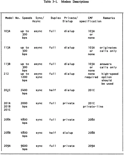
obtained with a variety of options. In most cases, the options recommended by the manufacturer should be used. but a few exceptions are noted in Table 3-1.
The two modems at the ends of a communications link must be either the same type or compatible types and have similar or compatible options. In a few cases, pairs of modems operate by having one member initiate the call (at the terminal end) and the other respond to it (at the FNP end); the Bell Model 113A/113B is an example of such a pair.
Table 3-1 lists Bell modems currently usable on a Multics system, and indicates, for each one, the speed(s) at which it can run, whether or not it is synchronous or asynchronous, whether it is dialup or private-line or both, what specification should be given in the dataset statement of the eMF, and any other important information. For more detailed information on a particular modem, refer to the modem's technical specification. which is available from the manufacturer.
COMMUNICATIONS PROTOCOLS
A communications protocol is a set of conventions observed by the two ends of a communications link in order to exchange data in an orderly and predictable fashion. The specification of a protocol may include conventions for controlling the physical state of the link, as well as the format and sequencing of blocks of data. Full duplex asynchronous links do not generally use protocols; half duplex asynchronous links usually require fairly simple protocols to determine the direction of transmission at any given time. Synchronous links generally use more elaborate protocols to ensure that each block of data is received correctly and in correct sequence.
• The following are examples of protocols supported by the Multics Communications
•
System, with the line types used to implement them (see Section 2 for a further discussion of line types) .
Examples of Protocols
Protocol: Level 6 ReI Line Type: Gl15
Protocol: Binary synchronous (bisync)
Li ne Type: BSC
Protocol: Honeywell polled VIP
Table 3-1. Modem Descriptions
Model No. Speeds Sync/ Duplex Private/ CMF Remarks
Async Dialup specification
103A up to async full dialup 103A
300 or
bps none
f13A up to async full dialup 103A originates
300 or calls only
bps none
1138 up to async full dialup 103A answers
300 or calls only
bps none
212 up to async fu 11 dialup none high-speed
*
1200 sync required option
bps should
be used
20JC 2qOO sync half dialup 20lC
bps
201A 2000 sync full private 20IC
.,nlD bps ... : ,.<III!!It.+..",.._l : .... .lII"It..
.. v . .., 1-"1 I VQ",,," I III,,"
201C
208A 4800 sync full private 208A
bps
208s
4800
sync half dialup208s
bps
209A 9600 sync fu 11 private 209A
bps
[image:20.612.85.541.63.610.2]AUTOMATIC BAUD RATE DETECTION
The autobaud feature of the Multics Communication System is designed to recognize/configure the baud rate (bits per second) of an asynchronous HMLC (or HSLA) channel at dialup time. The autobaud facility selects a 1200 baud rate if the high-speed
*
indicator is on (pin 12, for most modem types); otherwise it selects a rate of 110, 150. 300, or 1200 baud based on the sampling of bit changes for the incoming characters, "1", "L", "CR".Lead Control Selection of 1200 Baud
If the modem connected to the FNP turns "on" pin 12 of the cable connected from it to the FNP, the channel is set to 1200 baud and it is then handled in the normal manner. The FNP modem can be set to respond to a switch on the terminal modem which indicates that the terminal is operating at 1200 baud. The operation of the channel does not appear any different to the user than if a strictly 1200 baud channel is dialed into (there is no requirement for the user to type any characters before the login banner is received).
Bit Sampling Selects Other Bauds
If the signal on pin 12 is "off", sampling for the bit changes of an input character is performed. To accomplish this, the following sequence occurs:
1. The user establishes a connection with the host
2. The user types in either the letter "1" or "L" or a carriage return.
3. The software in the FNP scans the incoming bit stream looking for bit changes at 300 baud. Since the sample character is known ("1", ttL", "CR"), the changes in state of the bits ("0" or "1") indicate the timing necessary to transmit the bits, and therefore the baud rate of the channel is determined.
4. The channel is then handled in the normal manner. The answerback is checked (if required), the initial string (if any) is sent and the login banner is displayed.
Modems
Any asynchronous HMLC channel may be configured with the autobaud feature. For dialup cha...~ne1s not using special modems. automatic baud rate detection is possible only up to
1200 baud. In this range, most modems and acoustic couplers are able to interface with host modems.
There are several modems that can be used on channels configured with the autobaud feature which make
use
of the pin 12 lead change. Vadic (Model 3467) and Western Electric (Model 212A) are two manufacturers that make such modems. Special encoding techniques are required to handle the 1200-baud full duplex data over voice-grade dialup lines. For this reason,a
modem of one manufacturer may not necessarily be able to interface toa
modem of another manufacturer.Hardware Flow Control Using the
crs
Dataset Leadcrs
flow control protocol utilizes the capabilities of the FNP's asynchronous communications adaptor to remove the need for delay calculation to manage output flow control and alsoeliminates the need for output flow control information embedded in the data stream. This flow control is implemented for hardwired asynchronous communications lines (lines utilizing the FNP module ·control_tables'). It provides a stop-on-character output flow control.
This protocol utilizes the
crs
dataset lead (pin 5) to control output from the FNP tothe Data Termination Equipment (DIE). Ii
crs
is high, output will be sent; whencrs
drops, the current character will be finished and output will cease untilcrs
is raised again.Ths protocol is implemented such that a line must have all three leads (ers, CD and DSR) high to be initially on-line. After this point
crs
will act as a flow control signal, untii the line is hungup again by dropping either CD or DSR.Many terminals can utilize this protocol or a DTR flow control protocol. The DTR protocol uses t.he DTR lead from the terminal (pin 20) in the same manner. For DTR flow control a connector must be wired which connects the terminal DTR to the FNP CIS.
The use of a hardware protocol removes computational loading from the mainframe MCS since delays do not need to be calculated. It also lightens buffer loadings since buffer space for delay characters is not needed.
SECTION 4
CH~~NNEL
MASTER FILE
CHANNEL DEFINITION TABLE
The channel definition table (CDT). a data base in the segment:
>scl>cdt
describes the attributes of all Datanet Front-End Network Processors (FNPs) and communications channels on the system. Write access on this segment is necessary only for the initializer; read access is necessary f or users of certain metering commands.
The CDT is a binary table containing numbers and pointers as well as character strings. Therefore. it cannot be examined or modified with standard editors. The display_cdt command is used to print the contents of the whole CDT or selected entries. The reset_cdt_meters command resets the per channel count of dialups and total connect time. The tty_lines command lists all channels and their counters. When the system administrator wishes to add or delete channels, or to change the information about a channel in its CDT entry, he modifies the channel master file (CMF). converts the CMF into a new copy of the CDT with the cv_cmf command. and uses the install command to signal the answering service to modify the system's copy of the CDT. Thus. the site management can make certain changes in the site's configuration of terminal channels without waiting for a system shutdown.
Each FNP and terminal channel in the system has a CDT entry. This includes not only channels used for logins, but also special terminal channels, such as channels used by the message coordinator for the I/O of the initializer and daemons, and channels describing remote stations operated by the I/O daemons. These channels have flags set in the CDT entry indicating the way they can be used.
CHANNEL MASTER FILE
*
Syntax of the eMF
The eMF consists of a series of entries, one for each FNP or channel. Each entry consists of a series of statements that begin with a keyword and end with a semicolon. White space and PL/I-style comments enclosed by /* and */ may appear between any elements of the eMF. The last entry in the eMF must be the end statement Global statements specifying defaults appear anywhere before the end statement; the defaults that they specify are in effect for all subsequent channel entries, until they are changed by subsequent global statements. Except for the end statement, all statements consist of the statement keyword, a colon, the variable field of the statement, and a semicolon.
The entry for each FNP consists of an FNP statement, followed by statements describing the attributes of the FNP. Attributes not specified for an FNP are set from defaults supplied by the cv _cmf program.
The entry for each channel consists of a name statement naming the channel, which may be followed by statements describing the attributes of the channel. Attributes not specified for a channel are set from the defaults established by global statements or those supplied by the cv_cmf command. (See "eMF Default Statements" below.) Thus, a very simple CMF could consist of an FNP entry, a name statement for each channel, and an end statemen~ as follows:
FNP: A;
type:
DN6670;
memory:
64;
hsla: 1 ;
name: a.hOOO; name: a. hOO 1 ; end;
FNP ENTRIES IN THE eMF
A description of each statement in an FNP entry of the CMF is given below. FNP: <name>;
The F:N'"P statement is required. It specifies the tag of the FNP being described. Up to eight FNPs may be specified. A prph card with the same name is also required in the config deck. See the Mu/tics Programmer's Reference Manual, Order No.: AG91, for restrictions on the name of an FNP.
type: <FNP type>;
The type statement is required. It specifies the type of the FNP, which must be DN6670.
memory: <K -words>;
The memory statement is optional. It specifies the size of the FNP memory in K (1024 words). Acceptable values are 64 through 256. in increments of 32 (i.e., 64, 96, 128, etc.) The default is 64.
hsla: <number of hslas>;
The hsla statement is optional. It specifies the number of HSLAs (the number of HMLCs divided by four) configured on this FNP. The number may be zero through three; the default is zero.
image: <path>;
The image statement is optional. It specifies the pathname of the FNP core image to
be
used
for tlJ.is FNP .. The default is >system..,.~n~rgJ~l>!ll~s. Eacl1 F:NP may have a differeiii--oore image- -depending on- itS- configuration and supported line types. The path argument should specify a segment that is on the root logical volume to ensure that the FNP can be reloaded without having to worry about demounted volumes. (The FNP cannot be reloaded if path is on a demounted volume.)service: <active or inactive>;
The service statement is optional. If specified, the variable field must be either active or inactive. An active FNP is loaded and used by the system. An inactive FNP is not automatically loaded. However, it can be loaded by operator command or made active by installation of a new COT. (If an FNP is missing from the CMF at answering service startup time. rather than being included with a service type of inactive. it cannot be used during the current Multics bootload. The default is active. See "Changing Channel Configuration." below.)
CHANNEL ENTRIES IN THE eMF
A description of each statement in a channel entry of the CMF is given below. name: <channel name>;
The name statement is required. It specifies a unique channel name for the channel and can be up to 32 characters long. FNP-type channel names are divided into components separated by periods, with each component representing a level of multiplexing. A complete description of channel naming conventions appears in the
Multics Programmer's Reference Manual. Order No.: AG91. name: <channel name l>-<channel name 2>;
A pair of channel names can be given in the name statement The first N characters of the two names must be identical, where N is that portion of the names up to the digits representing the first and last subchannel numbers (the subchannel number in the second name must be greater than that in the first name). The effect of this form of the name statement is to sJ)PwCify a group of adjacent channels having identical characteristics. Their names are formed by starting with the first name. increasing the subchannel number by 1 to form each name, and ending with the second name. The number of channels in the group is equal to one plus the difference between the two subchannel numbers.
For example: the name statement ahlOO-ah220 specifies a group of successive channel names, the first of which is ahlOO, the second, ahlOl, the third, ahl02. etc., up to
*
generic_destination: <"string">;
The generic_destination statement is optional' and applies only to the slave and autocall service types. The string may be any site-specific value (e.g., tymnet, modem, protocol_converter_box) that does not resemble a channel name. If included in the CMF entry, the string is used to match the channel specifier used in a dial_out or privileged_attach operation.
baud: <baud_rate>;
The baud statement is optional. It specifies the baud rate of the channel. The baud rate must be compatible with the FNP line adapter type and must be chosen from the following list:
o
110 133 150 300 600 1200 1800 2400 4800 7200 9600 19200 40800 50000 72000The channel is assumed synchronous only if a synchronous line type is also specified. Zero and none are equivalent and may only be used for network channels, which are not attached through an FNP. The auto keyword requests automatic baud rate detection at dialup time for HSLA channels (see the discussion of automatic baud rate detection in Section 3). Baud rates higher than 19200 are valid only for synchronous channels.
NOTE: At speeds of 4800 baud and below, no more than 960 characters are sent to the FNP at a time.
The baud rate of a synchronous channel is not controlled by software. The baud statement for a synchronous channel simply informs the system of the speed of the hardware connection. The correct baud rate should be specified. however. so that the system can choose the optimal buffer size for the given rate.
attributes: <attr!, attr2, ... attrN>;
The attributes statement is optional. This statement applies only to login service channels. When this statement is used, the global attributes are overridden for this channel. If no attributes statement is specified, the global attributes are used. The 1\
character is used to negate the specified attribute. The following attributes may be specified:
audi t, 1\ audi t
if enabled, access errors on the channel are audited. check_answerback, I\check_answerback
if enabled, specifies that the answerback returned by the channel is to be checked against the one supplied in the answerback statement (see below). dont_read_answerback. "dont_read_answerback
if enabled, specifies that no attempt is to be made to read the answerback of the channel.
hardwired, 1\ hardwired
none
if enabled, specifies that the channel is directly wired, not connected through a switching system.
if enabled, specifies that all of the "1\" values of the attributes listed above are
assigned.
--set-.. :Jll00es,--Aset mOOes--- - --- -- - - -
---if enabled, spec---ifies that the modes associated with the terminal type of the channel are to be set when the chann~l dials up.
access_class: <"authorization {:authorization} Vi>
The access_class statement is optional. This statement specifies the authorization (sensitivity level and category set) of users allowed to use this channel. The authorization can be specified as a single value. in which case the channel is usable only by users with the specified authorization. The authorization can be specified by a minimum and maximum value, in which case the channel is usable only by users with an authorization equal to or greater than the minimum value and equal to or less than the maximum value. If specified. the authorization must be enclosed in quotes and must be expressed uSing valid site-defined authorization strings. (Use the print_auth_names command for a list of valid authorization values. See the Multics Programmer's Reference Manual Order No.: AG91, for a detailed description of the AIM mechanism.) For example, to specify that a channel is to be used only by users with an authorization of Ll,Cl. the access class entry would be specified as follows:
~
access_class: ilL 1 ,C1'I
To specify that a channel is to be used by users with an authorization in the range system_low to LS,C2, the access class entry would be specified as follows:
If the access class statement is not specified, the value is assumed to be that specified (or defaulted to) by the Access_class global statement
The administrator must be aware that the system cannot establish the authorization of a user for any channel except channels with a multiplexer_type value of "sty." For this reason, it is recommended that all channels except those identified as multiplexer_type sty should be· specified with a single access_class value. The only exception to this recommendation is for channels with a service_type value of "login" . These channels should be assigned an authorization range sufficient to cover the users who are to be
permitted to log in over the channel. answerback: <string>;
The answerback statement is optional. This statement applies only to login service channels. If spp-eifled, it m!!St have as a variable field a four~character string that is
the expected answerback for the channel. The star convention is allowed. -If the value is nUll, then no answerback check is made. Otherwise, the answerback code from the terminal is matched with the specified field; if they disagree, a message is printed to
terminal_type: <terminal type>;
The terminal_type statement is optional. If specified, its variable field must contain one of the terminal types defined in the terminal type table (described in the Multics Programmer's Reference Manual, Order No.: AG91); specified terminal types are checked against the current TIT when the CDT is installed.
The names of the possible terminal types can be ascertained by using the print_terminal_types command (described in the Commands manuaI). These names may be entered in uppercase or lowercase. The terminal type specified is set before any input or output is done to the terminal; thus, this statement overrides the default
*
terminal type (which is based on the line type and baud rate). The terminal_type statement does not force the terminal to remain the same type; it merely specifies the initial type. Thus, the answerback identifier, the -terminal_type login control argument, and process requests may override the terminal_type statement*
*
*
line_type: <line type>, <attrl>, <attr2>;
The line_type statement is optional. If specified, its line type field must contain one of the following line types:
none ASCII Sync G 115 BSC VIP POLLED_VIP X25LAP ASYNC1 ASYNC2 ASYNC3 SYNC1 SYNC2 SYNt3
unspecified (select protocol at dialup time) terminals: ASCI I, TN300, TTY33, TTY37 , TTY38 synchronous line, no protocol
remote computer interface, synchronous (GRTS) binary synchronous communications
Honeywell VIP 7700, single station Honeywell VIP 7760
HDLC X.25 frame level
optional site-defined asynchronous line types
optional site-defined synchronous line types
The line type specified is passed to the terminal control software before the channel
is enabled for listening, in order to set the line protocol to be used for handling communications on the channel. The default is ASCII.
dataset <name>, <attr>;
The dataset statement is optional. It identifies the generic type of dataset/modem being used on the channel. If specified, the name field must be chosen from the following list of Bell modem names, although any modem that is similar may be used.
103A 201C 202C5 202C6 208A 208B 209A
The attribute may be private_line to indicate that the modem is being used on a 4-wire circuit (see Section 3 for more information).
charge: <chargename or none>;
The charge statement is optional. If specified, its variable field must contain a charge name listed in the device prices array in the installation_parms segment (See the
Multics System Administration Procedures manual, Order No.: AK.50 for more information), or be "none." The charge type selects the per-hour surcharge for use of the channel.
service: <service type>;
These!yjcestatemenL is optionaL If- -specified, its variable field must-be one of the
following service types: login
me
slave autoca 11
inactive multiplexer
The service type determines whether the channel can be used f or normal logins or is
under control of some special software. The slave service is used only for special channels attached by the I/O daemons for bulk data input/output or other special subsystems. The mc service is specified for all message coordinator channels. The autocall service indicates that the channel is used to dial out using an automatic call unit The inactive service indicates that the channel exists but is currently not to be used. A channel installed as inactive can be changed only through installation of a new CDT. A channel rendered inactive because of an error condition or operator command (remove) can be changed eit..lJer through the operator attach command or installation of a new COT. The multiplexer service type is used for a multiplexer channel (see the discussion of multiplexers in Section 1). If a service type of multiplexer is specified, the multiplexer_type statement (see below) must be provided.
Access Control Segments (ACSs) specify access to the slave and autocall lines. Access
to login lines may be similarly controlled-c..,ee the description of tb.e attributes $
statement above.
A service type of slave must be specified for every channel that an I/O daemon driver directly attaches, and the names of such channels must be specified in the I/O daemon tables, >ddd>idd>iod_tables. Channels that are to be dialed to a daemon driver must be given a service type of login in the CMF, and dial identifiers must be
specified in the I/O daemon tables. (In order to use a particular registered dial identifier, a user must have rw access to the ACS. (See the Multics System Administration Procedures manual, Order No.: AKSO for more information.)
The default service type is login--meaning that the normal logins are allowed. multiplexer_type: <type>, <active or inactive>;
The multiplexer_type statement is required for channels with a service type of multiplexer and is invalid f or other channels. If it is specified, the variable field must
be ibm3270. vip7760. hasp, sty, or x2S. It indicates the type of multiplexer to be
comment <"string">;
The comment statement is optional. If' its variable field contains any blanks or punctuation, it must be enclosed in quotes. The variable field is saved in the CDT entry (up to 48 characters). The comment field may be used to identify the modem and telephone line connected to a channel. The comment is printed by the tty_lines command and by various answering-service programs that print error messages about the channel.
initial_command: <"initializer request">;
The initial_command statement is optional. This statement applies only to login service channels. If it is specified, the variable field must be a valid initializer command (e.g.. login. dial) line, enclosed in quotes. Whenever the channel dials uP. the initial command is executed before the first line is read from the terminal.
check_acs: <keyword(s»
Each keyword (described below) specifies that the channel aCcess control segment (>scl>rcp>CHANNEL_NAME.acs) is to be checked for appropriate access when the specified operation is performed. One or more keywords can be specified; if multiple keywords are specified, each must be separated by a comma. Use of this keyword assumes the creation of an access contol segment (acs) for the channel. See the
Multics Programmer's Reference Manual, Order No.: AG91 for additional information on access control segments.
login - The user must have rw access to the acs segment to log in over this channel.
slave - A user entering the "dial" or "slave" preaccess command must specify the -user control argument and must have rw access to the acs segment
priv_attach - The user must have rw access to the acs segment to attach this channel through the dial facility.
dial_in - A user accepting dial-in connections (via dial_manager_$allow_dials_ or dial_manager_$registered_server_> must have rw access on the acs segment of the connecting channel for the channel to be connected to the user's process.
dial_out - The user must have rw access to the acs segment to use the channel for dial_out requests.
all - Use all of the above keywords.
Individual keywords can be preceded by " to disable the particular keyword. The example below illustrates use of the disabling feature:
Check_acs: all;
name: a. hOO 1 ;
check_acs: Alogin
This sequence results in acs checking for all cases except logins from channel a.hOOl.
eMF Default Statements
Control statements that begin with a capital letter are global statements. Global statements exist for each of the statements that specify attributes. If no global statements are given in a eMF, the following set of defaults is assumed:
Attributes: Access_class: Answerback: Baud:
none;
system_low; 1111.
,
-300;Generic destination: 1111; Line_type: none; Terminal_type: none; Charge: none; Service: login; Comment: 1111;
Initial_command: Check_acs
1111.
,
GLOBAL STATEMENTS APPLICABLE TO ALL FNPS
The following additional global statements are used to set system-wide parameters: FNP _required_up_time: <number of minutes>;
The FNP _required_up_time statement is optional. It sets the minimum acceptable time between failures for all FNPs. If an FNP crashes after being up for less than the specified number of minutes, twice in succession, then it is not reloaded automatically. The default is five minutes. A value of zero disables automatic reloading of FNPs. Spare_channel_count <number of spare channels>;
The Spare_channel_count statement is optional. It specifies the number of channels the site expects to add to the eMF between system initializations (without rebooting Multics). In other words, if Spare_channel_count is 20, and the CDT in use at system initialization time specifies 100 channels, no more than 120 channels can be configured during that session. The LCT (logical channel table) is allocated in tty _buf with the number of entries equal to the number of channels in the CDT plus the number specified in this statement An FNP initialization error occurs if the number of new channels being added exceeds the spare channel count and an FNP load occurs before the system is reinitialized. The default is 10.
Changing Channel Configuration
The parameters that are changed at the next Multics bootload are actually set during answering service initialization, when either the startup or multics command is given. If
necessary, changes to these parameters can be made by copying a new CDT into >sc1 in the initializer process in admin mode, before the answering service is started. However, use of this method to replace the CDT destroys the channel usage statistics kept in the CDr entries. The ""preferred way to make a channel configuration change take effect immediately is to issue the initializer command, multics, and then with the initializer process in admin mode, modify the CMF, compile it, install the CDT using the install command (which preserves channel usage statistics), and then shut down and reboot Multics.
SAMPLE CHANNEL MASTER FILE
/*
Sample Channel Master File*/
Service: login; Charge: none; Terminal_type: none;
Line_type: none; Attributes: none; Baud: 300;
Access_class: "system_low"; FNP_required_up_time: 2;
Check_acs: priv_attach, dial_out; FNP: A;
type: DN6670; memory: 64; hsla: 1;
image: mcs; name: a.hOOO;
baud: 9600;
terminal_type: VIP7801;
attrributes: hardwired, dont_read_answerback;
initial command: "modes echoplex,"'tabs,tabecho,crecho,lfecho"; comment: "1200 baud, hsla 0, subchn 011;
/*temporarily disconnected, so comment it out: name: a. hOO 1 ;
baud: 1200; charge: caa;
termina1 type: ASCI I;
comment:-lIl200 baud, hsla 0, subchn 1, x319, vadicll ;
end comment out
*/
name: a.h002; baud: auto;
comment: " au to baud, hsla 0', subchn 2, x31611 ;
name: a.h003;
comment: 11300 baud, hsia 0, subchn 3, x32411;
Saud: 4800; name: a.h012;
service: slave; line_type: SSC;
dataset: 2oBA;
comment: "hsla 0, subchn 12, SSC";
name: a.h013; service: slave;
line_type: SSC; dataset: 208A;
comment: "hsla 0, subchn 13, SSCII;
name: a.h014; baud: 4800; line_type: SSC;
service: multiplexer; mUltiplexer_type: hasp;
terminal_type: 1 MFT_HASP_WORKSTAT 1 ON;
comment: "HASP multiplexer used for file transfer";
..
name: a.h014.opr; service: slave;
comment: "IMFT HASP daemon - operator control stream.";
name: a.h014.rdrl-a.h014.rdr8; service: slave;
comment:"IMFT HASP daemon I/O stream.";
name: a.h014.punl-a.h014.pun4; service: slave;
comment:"IMFT HASP daemon I/O stream.";
name: a.h014.prtl-a.h014.prt4; service: slave;
comment:"IMFT HASP daemon I/O stream.lI ;
name: a.h017; charge: caa;
terminal_type: ASCI I; attributes: hardwired;
name: a.h018; baud: 1200;
charge: caa;
terminal_type: ASCI I;
comment: "1200 baud, hsla 0, subchn 1, x319, vadic";
name: a.h020; baud: 2400;
service: multiplexer; multiplexer_type x25;
line_type: X25LAP;
terminal_type: X25_TYMNET;
comment: "TYMNET voice-grade HDLC X25 link.";
name: a.h020.00l-a.h020.028; initial command: echo;
comment: "TYMNET X.25 login subchannels";
name: a.h020.029-a.h020.032; service: autocall;
line type: X25LAP;
comment: "TYMNET X.25 autocall subchannels.";
name: a.h030;
line_type: POLLED VIP; baud: 4800;
service: multiplexer;
multiplexer_type: vip7760;
comment: "4800 VIP7760 polled controller"; terminal_type: VIP7760_CONTROLLER;
name: a.h030.dOl;
terminal_type: VIP7760;
comment: "Station 01 on polled VIP";
name: a.h030.d02;
terminal_type: VIP7760;
comment: "Station 02 on polled VIP";
end;
SECTION 5
MODIFYING COMMUNICATIONS CHANNELS
This section describes the recommended procedures for modifying the configuration of communicationS channels on the Multics system. In particular. it describes the procedures used to add a channel. delete a channel. or change the characteristics or status of an existing channel.
In general. one or two major steps are involved in modifying the channel configuration. The first step is changing the COT. which can be done in any sufficiently privileged process. as follows:
1. Use a text editor to make the necessary changes to the eMF;
2. Use the cv_cmf command to create a eDT from the new eMF (in >udd>sa>a) 3. Use the install command to install the new eDT.
The syntax of the eMF is described in Section 4, the cv _cmf command is described in Section 7. and the install command is described in the Multics Administration, Maintenance, and Operations Commands manual. Order No.: OB64.
The second major step. which is not necessary in all cases. is reloading (or reinitializing) the multiplexer of which the channel being changed is a subchannel. In the case of physical channels, -of course. this is an FNP (see the discussion of multiplexers and subchannels in Section 1). This is done by means of the load_mpx initializer command, described in the
Multics Administration, Maintenance, and Operations Commands manual. Order No.: GB64, and requires the use of the operator's console, a terminal dialed to the initializer, or the send_admin_command command (described in the Multics Administration, Maintenance, and Operations Commands manual, Order No.: GB64). It is suggested that the -check control argument to the load_mpx command be used to obtain information about possible inconsistencies in the configuration.