OPTIMIZED CORDIC DESIGNS AND APPLICATION OF BI-CORDIC
IN JPEG COMPRESSION
Aparna M. and Soni P.
Department of ECE, Sahrdaya College of Engineering &Technology, Thrissur, Kerala, India E-Mail: [email protected]
ABSTRACT
Growth of VLSI technology has inspired many designers to port algorithms into architectures. Coordinate Rotation Digital Computer (CORDIC) was one such algorithm which gained widespread attention, and many methods have come up for the implementation of CORDIC. Rotation of vectors through fixed and known angles has wide range of applications in digital signal processing, robotics, games, graphics, and animation. But, not much work has been done in the area of hardware optimization of CORDIC architecture. A few architectures which can be used for optimization of CORDIC for fixed angles of rotation are studied here. These designs were simulated and synthesized for Xilinx Field programmable gate array platforms and shown that device utilization can be improved using optimized designs. The most efficient design was identified and the same was selected for application in JPEG compression.
Keywords: CORDIC, rotation, FPGA, DCT, JPEG compression.
INTRODUCTION
The current researches in the field of high speed VLSI architectures and the advances in VLSI technology have provided the designers with significant momentum for porting algorithms into architecture. Some of the algorithms used in Digital Signal Processing require the calculation of elementary functions such as trigonometric functions. Table lookup method and polynomial expansions are the common software solutions used for the digital implementation of these functions. This requires large number of multiplication and additions/subtractions. In the year 1959, J. E Volder proposed a special purpose digital computing unit known as COordinate Rotation DIgital Computer (CORDIC) [1]. This happened while he was working on a real time navigational computer for the use in an aircraft. Algorithm was initially developed for the calculation of trigonometric functions and these were expressed in terms of normal plane rotations. The actual concept of CORDIC arithmetic is based upon the principles of two-dimensional geometry. J. E. Volder has described the iterative derivation of a computational algorithm for the implementing CORDIC. This algorithm can be used for the computation of trigonometric functions. The last decade denoted the completion of 50 years of the CORDIC algorithm [2] and, a wide variety of applications of CORDIC have come up in the last 50 years. Huge progress has been made in the areas of algorithm design and architecture development. The popularity of CORDIC has very much increased thereafter mainly due to its potential for high performance and low-cost implementation of a large class of applications, including the generation of trigonometric functions.
Through this work, an attempt to find an optimised CORDIC design is carried out. The selected design can be used to implement DCT and thus achieve the desired goals. As an application, the same can be utilised in JPEG compression. Hardware implementation of different CORDIC designs are done using Field
programmable gate array (FPGA) and the best one is found. FPGA provides the hardware environment in which dedicated processors can be tested for their functionality. They can perform a variety of high-speed operations that cannot be realized by an ordinary microprocessor. On-site programmability is the main advantage of using FPGA. Hence, it forms the ideal platform to implement and test the functionality of dedicated processors designed using CORDIC algorithm.
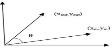
CORDIC FOR FIXED ANGLES OF ROTATION The conventional method of implementation of 2D vector rotation, shown in Figure-1, using Givens rotation transform is represented by the equations:
(1)
(2)
[image:1.595.335.530.660.744.2]where (xin, yin) and (xout, yout) are the initial and final coordinates of the vector, respectively. It should be noted that the hardware realization of these equations will require four multiplications, two additions or subtractions and also access to the table stored in memory for trigonometric coefficients. The CORDIC algorithm computes 2-Dimensional rotation using iterative equations consisting shift and add operations.
In the conventional CORDIC, any given rotation angle can be expressed in the form of a linear combination
of n values of elementary angles which belongs to the set {(σ. arctan(2-r)) : σ {-1,1}, r {1,2,……, n-1}}
The expression can be used to obtain an n-bit value of
(3)
As the angle of rotation for the fixed rotation case is known beforehand, it is advantageous to perform an exhaustive search to derive an optimal elementary angle set (EAS) instead of the greedy search. Furthermore, it can be observed that the hardware complexity of barrel-shifters alone is about half of that of a CORDIC circuit. Therefore by minimizing the complexity of barrel shifters, hardware cost of CORDIC circuits can be reduced. So, the optimization schemes for reducing the number of micro-rotations and for reducing the complexity of barrel-shifters for fixed-angle vector-rotation are studied. An optimized circuit named Bi-CORDIC, for this class of problem which is faster and involves less hardware complexity than the existing approaches is derived.
Optimization of the Elementary Angle Set
The rotation-mode CORDIC algorithm which is used to rotate a vector U= [Ux, Uy]T through an angle Ф to obtain a rotated vector V= [Vx, Vy]T is given by the equations below.
(4)
(5)
(6)
When n is sufficiently large,
(7)
T is the scale-factor of the CORDIC algorithm, given by
(8)
The reference CORDIC circuit for fixed rotations as per the above equations is given in Figure-2.
Figure-2. CORDIC circuit for fixed rotations.
In case of fixed rotations, Фi could be pre-calculated and the sign-bits corresponding to σi values could be saved in a sign-bit register (SBR) in CORDIC circuit. There is no need for the CORDIC circuit to calculate the remaining angle Фi during the CORDIC iterations. Rotation through any angle, 0 < ≤ 2Π can be mapped into positive rotation through 0 < ≤ Π/4 without any additional arithmetic operations. As the first step of optimization, rotation mapping can be performed so that the rotation angle lies in the range of 0 < ≤ Π/4.
Optimization of Set of Micro-Rotations
For achieving optimisation, the number of elementary angles in the set are minimised according to the accuracy requirements. The rotation mode CORDIC algorithm can therefore be modified accordingly to have
(9) Such that for a minimum number ‘m’
(10)
Now, the scale-factor K depends upon the set {i}. The accuracy of CORDIC algorithm depends upon the closeness of the resultant rotation ФA due to all the micro-rotations and the desired rotation angle. This will in turn determine the variation of actual rotation vector from the estimated value. Only a few elementary angles are sufficient to have a CORDIC rotation in the range [0, Π/4] and different sets of elementary angles can be chosen according to the accuracy requirement. Generalized expression for the scale factor given in (8) can be expressed explicitly for the selected set of m1 micro-rotations as
(11) Where k(i) for 0 ≤ i ≤ m1 represents the number of shifts in the ith micro-rotation. The k(i) for the above equation is referred to from Table-1. These values are resulting from the optimization algorithm 1.
Table-1. Optimization of full rotations with four micro-rotations.
Algorithm 1 to obtain optimal micro-rotations is as below:
Consider that Ф is the desired angle of rotation. Let ФA be the approximate angle of rotation. Consider that ФA is the resultant rotation due to all micro-rotations. The angle of deviation ΔФ can be defined as | Ф- ФA|. In the algorithm 1, Фwill be given as the input. Ф is defined as the maximum accuracy or the maximum tolerable error between desired angle and approximate angle. The parameters k(i) and σi that can minimize the objective function ΔФ is searched by the optimisation algorithm. The algorithm starts with the single micro-rotation, i.e., m=1, and if the micro-rotation that has smaller angle of deviation than Ф cannot be determined, the number of micro-rotations is increased by one and the optimization algorithm will be run again.
Next step is to work out an exhaustive search in the optimization algorithm to search entire parameter
space for all the combinations of k(i) and σi which can minimise ΔФ. The algorithm starts with m=1. ΔФ is calculated and for each m a check is done to find if ΔФ˂ Ф; if not m is incremented. For Ф=0.04 , a set of four micro-rotations is found enough. From Table I, it can be shown that rotations through any angle in the range 0 ˂ Ф ≤ 4
5°
(in odd integer degrees) could be achieved with maximum angular deviation ΔФ=0.037 , where ΔФ= | Ф- ФA|. Using two selected micro-rotations, the rotations could be achieved with maximum angular deviation ΔФ=1.875°.
Table-2. Optimization of scaling factor.
Implementation of Four Micro-Rotations
small look up table. CORDIC circuit for complex constant multiplications is shown in Figure-4.
Figure-4. CORDIC cell for constant complex multiplications.
CORDIC circuit for four micro-rotations can be implemented for all angles in the range 0
°
to 45 . K(i)represents the number of shifts in the ith micro-rotation where i ranges from 0 to 3.
Figure-5. Simulated output of four micro-rotation CORDIC circuit.
Implementation of Two Micro-Rotations
Using only two micro-rotations CORDIC circuit can be implemented. Such circuit is otherwise known as Bi-rotation CORDIC cell. CORDIC circuit using two micro-rotations can give accuracy up to 1.857 . Although this accuracy is inadequate in many situations, it can be used for some applications where the outputs are quantized, e.g., in case of speech and image compression. Therefore, an efficient CORDIC circuit to implement a pair of micro-rotations is considered and named as Bi-rotationCORDIC. This circuit is shown in Figure-6. At a later stage of the work, bi-rotation CORDIC cell is used to perform JPEG compression.
The bi-rotation CORDIC involves only a pair of barrel-shifters consisting of only one stage of 2:1 MUXes. The control-bit for the barrel-shifters is 0 for the first rotation (no shift) and 1 for the second micro-rotation (shift through k(1)-k(0)). The control bits are
generated by a T flip-flop, since they are 1 and 0 in each alternate cycle. Thus in bi-rotation CORDIC cell, the rotation is implemented in two iterations. In the first iteration no pre shifting is done and k(0) is the number of shifts. But in the case of second iteration, the input to the second stage is output of the first stage pre shifted by k(0).
The number of shifts in the second iteration will be k(1)-k(0).
Figure-6. Bi-rotation CORDIC circuit.
Minimization of Barrel Shifter Complexity
In the CORDIC circuits for eight, four and two micro-rotations, barrel shifters are utilised. A barrel shifter is a digital circuit that can shift a data word by a specified number of bits in one clock cycle. Barrel shifter for a maximum of S shifts for word-length L is implemented by [log2 (S+1)] stages of de-multiplexors. Here each stage requires L number of 1:2 line MUXes. Thus, hardware-complexity of barrel shifter increases linearly with the word-length and logarithmically with the maximum number of shifts. Using simple hardwired pre-shifting, effective word-length in the MUXes of the barrel shifters, and also the number of stages of MUXes can be reduced.
Figure-7. Hardwired pre-shifting in basic CORDIC module.
to the barrel-shifters, since the less significant bits (LSBs) would get truncated during shifting. The barrel-shifter, therefore, needs to implement a maximum of shifts only, where is the maximum number of shifts in the set of selected micro-rotations. The output of the barrel-shifters are loaded as the LSBs to the add/subtract units, and the MSBs of the corresponding operand of add/subtract unit are hardwired to 0. Therefore, the hardware-complexity of a barrel-shifter could be reduced by the hardwired pre-shifting approach as shown in Figure-7. The time involved in a barrel-shifter could also be reduced by hardwired pre-shifting, since the delay of the barrel-shifter is proportional to the number of stages of MUXes, and it also is possible to reduce the number stages by hardwired pre-shifting.
Figure-8. Simulated output of hardwired pre-shifted 4 micro-rotation CORDIC circuit.
From the Synthesis report of the above circuits, it can be seen that the device utilization is at a maximum for eight micro-rotation CORDIC circuit. Here the number of slices is 67% and the number of 4 input LUT’s are 64% when implemented for Xilinx Spartan FPGA. Then, in case of four micro-rotation CORDIC circuit, device utilization is a little reduced and sums up to 44% of the total number of slices and 41% in case of number of 4 input LUT’s. In case of Bi-rotation CORDIC cell, it can be seen that the design is highly optimized and there is a huge decrease in device utilization. Number of slices is reduced to just 7% and number of 4 inputs LUT’s is reduced to 6%.Thus among the three, Bi-rotation CORDIC can save the hardware cost enormously.
APPLICATION OF CORDIC IN JPEG COMPRESSION
Image compression is aimed at reducing the size of the image representation while keeping most of the information contained in the original image. Several standards are available for image compression and decompression and JPEG compression is the most widely used form of lossy image compression. It is based upon the discrete cosine transform (DCT) [3]. The most basic form of sequential DCT based compression is the baseline JPEG compression algorithm. It makes use of transform coding, quantization, and entropy coding, at an 8-bit pixel resolution and as a result, a high-level of compression can be achieved. The compression ratio achieved is mainly due
to the sacrifices made in quality. JPEG system assumes that each block of data input is 8x8 pixels.
Discrete Cosine Transform
The basis for the JPEG compression standard is the discrete cosine transform (DCT). Ahmed, Natarajan, and Rao originally proposed use of the DCT in 1974[4], and it has become the most accepted transform for image and video coding. DCT permits efficient compression for JPEG by allowing quantization on elements that are less sensitive. Since DCT algorithm is completely reversible, it is useful for both lossless and lossy compression techniques. For JPEG, a two-dimensional DCT algorithm is used, which is basically the one-dimensional version which is evaluated twice. The DCT is operated two dimensionally taking into account an 8 by 8 block of pixels. The resulting data set is an 8 by 8 block of frequency space components, the coefficients scaling the series cosine terms, known as basic functions. There are two advantages of using the DCT algorithm. First it is possible to concentrate image energy into a small number of coefficients. Second, it minimizes the interdependencies in between the coefficients. These two advantages in effect states why this form of transform is used for the standard JPEG compression technique. Utilising DCT, great pictures can be produced at low bit rates and is fairly easy to implement with fast hardware based algorithms.
Quantization
Quantization is an extremely important step in the JPEG compression algorithm, as it helps to reduce a considerable amount of data, thus reducing the entropy in the data stream. The quantization is an integer division of all the 2D-DCT coefficients by constants. The quantization step will perform the operation:
(12)
where Cqij is the quantized coefficient; Cij is the
2-D DCT coefficient; Qij is the quantization constant.
Quantization is the operation that introduces data losses in the JPEG compression process. This intended to remove the less important components to the visual reproduction of the image. The aim of quantization is to compress the image as much as possible without visible artefacts. Each step size ideally should be chosen as the perceptual threshold for the visual contribution of its corresponding cosine basis function. Larger quantization values will result in visual artefacts. Quantization is an integer division of each DCT coefficient by the corresponding constant, and rounding the result to the nearest whole number. The division can be implemented very efficiently in hardware as a shift operation if the quantization factors are restricted to powers of 2.
Parallel to Serial Conversion
pipeline controlled by the clock until filled. The eight words dout0 to dout7 are then loaded into the serial pipeline which pass the data out of the circuit in a bit-serial fashion, least significant bit first.
Zigzag Scanning
The zigzag process is an approximate ordering of the basic functions from low to high spatial frequencies. This process will give more compression by putting more order in the entropy. Essentially our lower-frequency components, which describe the gradual luminance changes, are more important to the human visual system than the high frequency changes. By ordering the more important coefficients in the beginning of the 8x8 block, we can expect more runs of zeros later after quantization, toward the end of the 8x8 block.
Figure-9. Sequence obtained by zigzag.
Run Length Coding
Run length coding is the first step in entropy coding. This is implemented by assigning a code comprising run length and size, to every non-zero value in the quantized data stream. The run length is a count of zero values before the non-zero value occurred. The size is a category given to the non-zero value which is used to recover the value later. Additionally, with every non-zero value a magnitude is generated which determines the number of bits that are necessary to reconstruct the value. It will indicate possible values in the size category that can be correct. Run Length coding is a basic form of lossless compression.
Figure-10. Simulation of JPEG compression.
CONCLUSIONS AND FUTURE WORK
CORDIC is a powerful algorithm, and a popular algorithm of choice when it comes to various Digital
Signal Processing applications. Implementation of a CORDIC-based processor on FPGA gives us a powerful mechanism of implementing complex computations on a platform that provides a lot of resources and flexibility at a relatively lesser cost. Further, since the algorithm is simple and efficient the design and VLSI implementation of a CORDIC based processor is easily achievable. As part of the project, a basic CORDIC circuit is designed and simulated using Xilinx ISE as the synthesis tool, coded using Verilog HDL. The output of the CORDIC module is analyzed and verified on the test-bench. Next, the CORDIC circuit for four micro-rotations was designed and simulated, followed by the design and simulation of CORDIC circuit for two micro-rotations. Later, all the designs were synthesized and implemented on Xilinx Spartan 6 FPGA. Bi-rotation CORDIC was found to be the most optimized design with very less hardware cost. As an application of the Bi-rotation CORDIC, the same was utilized for JPEG compression. Bi- rotation CORDIC cell was used to implement DCT, one of the most important stages in JPEG compression. JPEG compression was successful using these DCT values.
Several advantages can be seen in CORDIC based designs and these can be used while building micro-architectures with no multipliers. Implementation area, measured by the gate count of the FPGA material, can be saved by using this principle. Different architectures can be considered, area can be reduced, and at the same time a relatively high performance can be kept by adopting the CORDIC design principle. In the course of implementation, there were several ideas that were never integrated into the design. JPEG baseline algorithm is used here and many extensions are available. The building blocks used in this design can be utilized in the JPEG extensions, as well as other compression algorithms. Also, there are many optimizations which can be performed on the CORDIC design to improve throughput. By studying a known data set, optimised quantization tables can be used to further compress the data in the image. This could improve compression, and would only require some design changes on the FPGA.
REFERENCES
[1] P. K Meher and Sang Yoon Park. 2013. “CORDIC Designs for Fixed Angle of Rotation”, IEEE Trans. VLSI Systems, Vol .21, No.2.
[2] P. K. Meher, J. Valls, T.B. Juang, K. Sridharan and K. Maharatna. 2009. “50 years of CORDIC: Algorithms, architectures and applications,” IEEE Trans. Circuits Syst. I, Reg. Papers, Vol. 56, No. 9, pp. 1893–1907.
[4] N. Ahmed, T. Natarajan and K. R. Rao. 1974. "Discrete Cosine Transform," IEEE Transactions on Computers, Vol. C-23, No. 1, pp. 90-93.
[5] Y. H. Hu and S. Naganathan. 1993. “An angle recoding method for CORDIC algorithm implementation,” IEEE Trans. Comput., Vol. 42, No. 1.
[6] Y. H. Hu and H. H.M. Chern. 1996. “A novel implementation of CORDIC algorithm using backward angle recoding (BAR),” IEEE Trans. Comput., Vol. 45, No. 12, pp. 1370–1378.
[7] C.S.Wu, A.Y.Wu and C.H. Lin. 2003. “A high-performance/low-latency vector rotational CORDIC architecture based on extended elementary angle set and trellis-based searching schemes,” IEEE Trans. Circuits Syst. II, Analog Digit. Signal Process., Vol. 50, No. 9, pp. 589–601.
[8] J. S. Walther. 1971. “A unified algorithm for elementary functions,” in Proc. 38th Spring Joint Comput. Conf., pp. 379–385.
[9] Y. H. Hu. 1992. “CORDIC-based VLSI architectures for digital signal processing,” IEEE Signal Process. Mag., Vol. 9, No. 3, pp. 16–35.
[10] S. A. K. Jilani and S. A. Sattar. 2010. "JPEG Image Compression using FPGA with Artificial Neural Networks," International Journal of Engineering and Technology, Vol. 2, No. 3, pp. 252-257.