o
o
1. INTRODUCTION
Flight simulators are based on the theory that the behavior of an air-craft in flight can be represented mathematically by a system of equations in which certain "output" variables, such as position coordinates and ori-entation angles, ch~rige appropr iately with time in accordance with certain "input" variables, such as throttle position and stick position. In order to build a flight simulator, it is necessary first to develop a system of equa-tions that will accurately represent the characteristics of a particular air-craft, and then to design and assemble a computer that will solve these equations in accordance with a variety of inputs representing the physical situation and provide accurate output signals with which to drive cockpit instruments, ,!generate control forces, and activate all of the peripheral equipment (ed g., motion system, visual <;lisplay) required for a realistic training environment.
.<
Until ~ short time ago, flight simulators were based exclusively upon analog computation techniques, in which aircraft flight quantities (altitude, airspeed)! are analogously represented by electrical and mechanical quan-tities (vc6ltages, shaft positions) in an electromechanical network that
duplicat~s the interrelationships between the various subsystems that make
lJJ>
a particular aircraft. In recent years, however, in spite of the many ~dvances made in analog computing technology, the flight simulator, along/with the aircraft it simulates, has increased in complexity to the point/where designers have had to supplement the capabilities of conven-tiomil analog equipment by incorporating digital equipment inever-inc~'~asing amounts. .
/
.The fundam~ntal difficulty with analog simulators is that the organiza-tion of the elements of these machines must be v~fy similar to the organi-zation of the mathematical equations describing .the operational system. That is, for every element in an equation therejnlUst be a corresponding element in the computer which, as a rule,
series
only this one function. Thus, as the complexity of the equations incr¢ases, so does the complexi-tyof the analog hardware. Furthermore, oq.l:e an analog simulator has been built, any changes in the operational system, and hence in the equa-tions of the system, can be implemented only by making corresponding changes in the hardware of the analog computer, with the attendant penalty of lost computer time.Contrast this with the great flexibi~tty of the digital machine, whose elements are organized to carry out the step-by-step instructions of a written program. Any changes in the ,equations being solved affect only the written program and do not requi:fJ~ changes in the hardware of the computer itself. That is, there is nd downtime involved when making the actual changeover except the time---r-equired to load the new program
(generally only minutes). Add to these qualifications the inherent accuracy
of the digital computer, plus its reduced overall size and power consump-tion, and it becomes apparent that a digital approach to real-time aircraft simulation is much to be desired.
The first serious~tfempt to apply digital,c'6mputing techniques.to the problem of real-ti1l,)e' flight simulation w~fnitiated in 1950, when a joint Air Force-Navy pfogram was establisg.efi at the Moore School of Electrj... cal Engineerin ; University of Penn lvania. The Moore School's g-time associa ·on with the develop nt and application of digita omputing techniques ade it a natural cho·ce to head the program, w ·ch was named UDOFT ( iversal Digital Ope ational Flight Trainer). e intent of the UDOFT roject was to devel a suitable digital camp- er and program it
!
to solv:,e a set of flight equa ons, so that the feasibity of digital simulation
in re~l time could be est lished.
/ (
.The equations used by the Moore School were taken from two existing analog flight Simulators, representing the F9F and the F100 fighter air-craft. This was done so that a direct comparison of flying qualities of the digital and analog simulators could be made. No attempt was made to de-rive new equations directly from the aircraft data because it was intended that the degree of simulation should remain the same.
By 1958 the development of the mathematical techniques had been com-
0
pleted and the logical design of the UDOFT computer was well defined. Actual construc.tion of the digital computer was accomplished by the Sylvania Corporation and was completed in 1960. The results of the pro-gram clearly ~stablished that a digital computer could successfully be used for the lieal-time simulation of' aircraft flight.
In spite: of the fact that it performed successfully, h'owever, UDOFT was (and is) far from being the fiI:1al answer to the problem of all-digital flight simulation. In the first place, it was never inten.d.ed to be more than a fe~sibility tool, preprogrammed to solve a partibular set of aero-dynamic,equations, and, as a result, its application to! simulation prob-lems in .:general (function generation, Boolean operations) was severely limited. What was needed was a new species of speciajl .. purpose computer . "
d~sign,ed,
likeUDO~~,
exclusively for flight simulati!bn purposes, but~
WIth~dequate
capablllty to accommodate the totalran~e
of computationalrequ~rements associated with the modern flight simu~ator. The Mark I
is such a computer. i
f
Link began developing the Mark I with the idea tijat the computer should be economically justifiable for use in flight Simulators under sub-st&'ntially the present cost structure and should capitalize on the undeniable
a~vantages of digital computation: high accuracy, extreme flexibility, high
r!eliability, small Size, and reduced heat dissipation.j The main objective,
~owever, was to obtain a digital computer suitable f9r use in simulators
j
)
0,
•
o
that
customers,~6th
commercial and military, could afford. As a result, the Mark I is a rather unusual computer in that it is designed for maximum usability in the/simulation and training equipment domain.The
Ma,rk
I computer is a highly specialized combination of proven techniques that completely elimi~ates the risk inherent in the use of de-velopmenqil circuits and compqrtents, while at the same time reducing the overall cost and complexi~ of the computer to the economic level mandatory for flight simulatQf.s. With the exception of some minor in-novations, Link makes no cHtim that the Mark I computer advances the state qf the digital comput~f art in general. It is simplya
special com-bination of existing digital' computing equipment that uniquely satisfies the cpmputation requiret¥Emts for simulation devices./
The computations Iiandled by the Mark I can, if carefully simplified, be/handled in margina~j'fashion by other large-scale computers (the CDC
1~04, the IBM 7090, ~he fastest of the Philco Transac series, the PDP3, ~d p.erhaps others). / However, because the Mark I is designed specifi-,cally to accommoda~e the particular problems of real-time Simulation,
it is substantially le;~s expensive and will be much easier to program
than any commer1y available computer wo¢d be In this application.
I
i
2. ADVANTAGES OF MARK I APPROACH TO FLIGHT SIMULATION
The tasks required of a computer used for flight simulation are highly specialized. To be completely useful, the computer must be capable of:
1) Performing all required mathematical operations peculiar to simulation problems. These operations are addition, subtraction, multi-plication, division, squaring, square root, integration, level and polarity detection, and scaling.
2) Performing all required Boolean (switching logic) operations peculiar to simulation problems. These operations are LOGICAL SUM (OR), LOGICAL MULTIPLY (AND), and INVERT. The Boolean opera-tions should lend themselves to the generation of pseudo-Boolean funcopera-tions (for example, radio call1eUer generation).
3) Storing large amounts of permanent data, such as curves of arbitrary nonlinear functions, constants, and parameters defining navi-gational facilities.
4) Accepting large amounts of rapidly changing input data from the cockpit and instructor's controls. These input data should be accepted
in raw form, with a minimum need for intermediate modification or trans-
0
lation before the computing process commences.5) ProceSSing all the current input data and permanent data in ac-cordance with a program of instructions that is completely flexible. The program should be versatile enough so that certain parameters having critical dynamic characteristics (e. g. , Euler angle rates) and critical accuracy and resolution requirements (e. g., altitude, latitude, longitude) can be given special consideration without reducing the computing effi-ciency or useful memory capacity.
6) Providing a large amount of new, smoothly changing, accurate answers. These answers should be provided in a form that requires a minimum amount of conversion or translation in order to be useful.
7) Accepting new, modified, or corrected program instructions and permanent data changes rapidly and with ease.
8) Minor program revision or updating by personnel with a basic analog background.
In specifying the characteristics of the Mark I, Link carefully studied the pertinent features of available digital computers in relation to the re-quirements of flight simulation. In examining these rere-quirements, they were divided into categories so that areas of computation with similar
4
- - - - : - - - -- -
o
o
problems could be taken together. These categories are: 1) Flight equations
2) Engines and aerodynamic coefficients 3) Accessory systems and instructor inputs 4) Radio navigation -/.;;
,. "" ,c" "'i'" ";''L,
The solution of flight equations requires that many calculations be performed at high speed, over and over again. A high repetition rate is necessary in order to avoid lags in the computations, which would cause the simulation to depart from realism. The experience of the Moore School with the UDOFT program had shown that an iteration rate of 20 times per second was required for an adequately responsive solution of the equations of motion. This requirement demands a high-speed, parallel-arithmetic computer with a random-access core memory.
The Mark I is such a computer. It performs all of the required arith-metic operations (add, subtract, multiply, divide, square, square-root, shift, absolute value) under program control, and with great rapidity. If no other operations were considered, the Mark I could perform as many as 163,840 additions, or 27,273 multiplications, or 23,405 division opera-tions per second. These times include all instruction and data access
Ctimes as well as the time required to perform the operations. From this -point of view, the Mark I ranks with the faster digital computers available at the present time.
The calculation of engine parameters and aerodynamic coefficients involves the generation of a large number of arbitrary functions of one, two, and three variables representing empirical aircraft data. In conven-tional digital computers, it is necessary to develop a polynomial expression for each arbitrary function and then program the computer to solve the expression for all values of all variables. These operations are very time-consuming and also require a high degree of skill in the mathematical operations of data reduction and curve-fitting to achieve a satisfactory poly-nomialexpression. In addition, the functions can change quite rapidly, so that a high iteration rate is necessary in the solution of the polynomials, and, since many program steps are involved, the burden on the computer is quite high.
In the Mark I, function generation is handled by straightforward linear interpolation, using straight-line-segment function curves which in most cases are taken directly from aircraft data curves. The function interpo-lations in the Mark I take place sequentially, are repeated 10 times per second, and are done independently of the main program - i. e., they
L
require no instructions from the main program, and therefore no attention from the programmer. The stored function curves are entered directly as numerical data along with the core memory address of the interpolated result. Because of this simplicity of organization, it is quite easy to change individual function curves as air craft data change, without the ne-cessity for extensive mathematical opera tions.
The simulation of aircraft accessory systems is primarily a problem in switching logic, requiring only a small amount of arithmetic computa-tion. This means that the computer has to be able to handle large numbers of Boolean {one-bit} words representing switching {on/off} functions. Many computers have the capability to incorporate two or more independent bits of Booleari information in one computer word; however, they usually re-quire several extra program steps to extract a desired item from the various items contained in a given word.
o
The Mark I has a separate arithmetic unit that can perform program-med Boolean operations on as many as 2048 independently addressable, single-bit words stored in a functionally separate section of the'random-access core memory. Since each single-bit word can be individually ad-dressed, no extra instructions need be written or executed to obtain ac-cess to the desired word. This arrangement conserves the expensive core memory, and thus helps to keep the Mark I economically priced.
Further-more, by minimizing the number of instructions that must be performed,
0
it also reduces the labor of initial programming and reprogramming. Inother words, because the Mark I has been designed to operate on single-bit words directly, it is ideally suited to the computations associated with accessory systems. Some relays may still be required in cases where large amounts of power are switched, but the racks of relays traditionally associated with logic circuits will be entirely absent from the Mark I flight simulator.
Radio-navigation problems, important as they are from a training standpoint, have always been extremely difficult to simulate with a high degree of realism. The maximum incorporable repertory of radio facili-ties has always been severely limited, and the accuracy of simulation has often been poor owing to the nature of the computing equipment. Now, with the advent of digital simulation, there is promise of tremendous im-provement in the simulation of radio facilities. Not only is greatly in-creased accuracy possible, but the number of facilities that can be repre-sented is increased by a factor of nearly a hundred.
The Mark I computer was designed with the problem of radio facility representation very much in mind, especially the problem of selecting eligible transmitters for reception by the aircraft receiver~. The Mark I provides a repertory of 350 separate and independent navigation transmitters,
6
---~
o
and, on the basis of receiver tuning and aircraft geographic position, lects for each receiver the one best transmitter to be received. This se-lection process is carried out for each navigation receiver aboard the simulated aircraft, and is accomplished automatically, without operator control and without using a single program instruction. Programmed operations are required only for the calculations associated with the nature of the transmitter and receiver and with the simulated physical situation; the actual selection of a transmitter for a given receiver and the transfer of the stored data that define the location and characteristics of that trans-mitter are accomplished in parallel with the main program, like function generation, and do not subtract from the time available for executing pro-grammed arithmetic operations.
A digital simulation computer must be able to handle large numbers of inputs and outputs, both analog and Boolean. Conventional machines can do this only at the expense of precious program space. The Mark I input/output system, however, operates automatically. No instructions are required in order to accomplish the input/output memory transfers or conversions to or from digital form, and no time is subtracted from the time available for the execution of the general program. The input system automatically scans analog inputs, converts them to digital form, and loads them into preassigned core memory locations. Similarly, the output system obtains variables from preassigned core memory locations, converts them to analog quantities, and makes them available on separate output lines for use outside the computer. In addition, a large number of Boolean (single-bit) input functions are scanned and inserted into pre-aSSigned core memory locations, and a large number of Boolean outputs are available from preassigned core locations. In all, a total of 126 analog inputs, 192 analog outputs, 1024 Boolean inputs, and 256 Boolean outputs can be accommodated by the Mark I.
Because the Mark I program is changed infrequently (in contrast to
A-D
the typical scientific computer application), it can be stored more or less
-E..e~~ane~gg.¥...2.1l.~ magneti~ storage drum. Conventional digital computers
utilize the core memory for instruction storage, and, because core memor-ies are so expensive, have a rather limited capacity for the storage of pro-gram. In order to utilize the available storage space efficiently, elaborate programming techniques, such as looping, branching, and instruction modi-fication, are necessary. In conventional digital computers, a time penalty is also paid, because after the execution of each instruction the computer must wait for the next instruction to be obtained from the core memory.
(- This is not so in the Mark I, because the instructions are stored on the \ drum in the exact order in which they are performed, and as one
instruc-l.,
tion is being performed by the arithmetic element, the next one to beper-I
formed is moving into pOSition to be read. When it is in position"it isI
read and performed without waiting. Most instructions require only oneI,,-~access to the core memory, others require no access at all,and no in-structions require more than one core memory access.
Since program instructions are never modified intentionally by the Mark I computer, errors cannot be made in the process and the instruc-tions will therefore not be altered accidentally - as could happen in a con-ventional digital computer. Storage of the program on a magnetic drum is also far less expensive than an equivalent core memory. The Mark I con-tains program storage space for 45,056 instructions. Of these, 4096 are performed 20 times per second, 8192 are performed five times per second, and 32,588 are performed every 0.8 seconds. This, of course, does not include the capability represented by the automatic radio system, the func-tion generator, and the automatic input/output system - none of ,which use any of the 45,056 instructions.
o
Link studies have indicated that 45,000-instruction storage is
0
more than adequate to accomplish a degree of simulation which is equiva- . lent to, and in many cases better than, that of present-day simulators.Estimates of required program space were based on a mathematically rigorous axis system and uncompromising accuracy throughout all com-putations. The use of equations of this degree of rigor in an analog simu-lator would be prohibitively expensive, and in many cases would be intol-erable from the standpoint of dynamic accuracy and stability because of the inherent limitations of analog equipment. For purposes of comparison, it is estimated that the Mark I has a computing capacity equivalent to that of a highly flexible analog system containing 150 servos, 1200 operational amplifiers, 1000 potentiometers, and 20,000 precision resistors. In ex-ploiting this capability, the designer of the Mark I flight simulator has the option of incorporating many additional features not found in present-day analog flight simulators.
8
o
3. FUNCTIONAL DESCRIPTION OF COMPUTER
3. 1 GENERAL DESCRIPTION
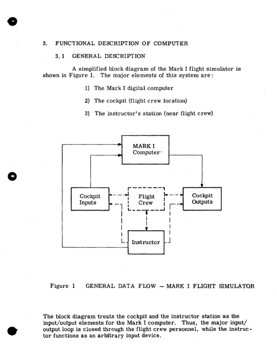
A simplified block diagram of the Mark I flight simulator is shown in Figure L The major elements of this system are:
1) The Mark I digital computer 2) The cockpit (flight crew location)
3) The instructor's station (near flight crew)
MARK I Computer"
.
r---,
Cockpit 1'---....I I Flight
J..--.
CockpitI
Inputs ~-l I Crew
I
,-
OutputsI
I
L.. _ _ - . __ ..J
I
I
I II
I
t II I
L Instructor c-
J
Figure 1 GENERAL DATA FLOW - MARK I FLIGHT SIMULATOR
[image:11.617.15.566.46.731.2], I FUGHT CREW
ct
II
OR INSTRUCTOR
CONTROL -:::
FLIGHT CREW --<Y'
OR '
INSTRUCTOR SWITCHES
....
RADIO AIDS0 OPERATOR
INPUTS
FLIGHT CREW
RADIO CHANNEp--.lTRANSLATORI SELECTOR
I
,I
o
Figure 2~~--==~~~~~~---"----,-"---.
,ose I LLA TORS ENGINE
TIRES
INSTR CONTROL
BOOLEAN _I
-APU COCKPIT
SPEAKFR
I
BOOLEAN DCI
MARK I DIGITAL I DC BOOLEAN COMPUTERI I DC
BOOLEAN
I
~
BOOLEANDC
DC
BOOLEAN
AIRFLOW
Mise
I _
-INDICATOR LIGHTS
- - - . 0 AND FLAGS
I
SYNCHRO TYPE INDICATOR.IAMPL ") .I~
INDICATOR METER TYPE
FLIGHT CONTROL FORCES
I---~~OCOCKPIT MOTION
HEADPHONES
[image:12.793.88.681.111.587.2]o
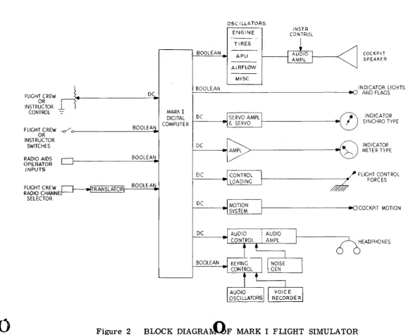
Figure 2 is a more detailed block diagram of the flight simulator. From this diagram, it can be seen that the major problems to be solved by the computer are:
1) Accept all cockpit and instructor inputs, such as flight controls, engine controls, accessory system switching functions, radio-navigation controls, and malfunction controls.
2) Compute solutions to all aircraft equations of motion throughout the flight envelope of the aircraft for normal and emergency flight situations.
3) Compute solutions to all engine equations for normal and emergency operation of the engines.
4) Compute solutions to all switching logic equations used to define aircraft accessory systems operation, for normal and emergency
operatio~.
5) Compute all navigation equation solutions.
6) Provide appropriate outputs to cockpit and instructor station indicators, lights, audio devices, recorders, and control force generating equipment.
The manner in which each of these problem areas is handled is described
in detail in subsequent sections. In general, the Mark I digital computer will perform all of the arithmetic and Boolean operations required in the modern flight simulator. It will solve the equations which represent the characteristics of the airframe, the onboard systems (including engines), and the complete radio-navigation problem.
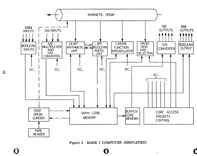
As shown in Figure 3, the Mark I computer operates in accordance with a written program stored on a magnetic drum. Using a special tape reader and high-speed drum loader, the many thousands of instructions constituting a typical flight simulator program are. stored on the drum in the order in which they are to be performed. During the operation of the computer, these instructions are read and performed in the order in which
[image:13.614.42.524.29.768.2]i II ~ N
o
..
MAGNETIC DRUM
1024
INPUTS
illl
I
~iNPUTs
BOOLEAN INPUTS
AID
MULTIPLEXER ANDNO
CONVERTERARITHMETIC F 24 BIT 1 ..
11
BOOLEAN BITj
P.C. RC.
I
FAST ~ - ---DRUM
LOADER
~---•
UNIT ARITH.
UNIT ...---r
P.C.
P.C.
,
.
.
,
MAIN CORE MEMORY
•
•
RADIO AIDSPRE-192
OUTPUTS D/A CONVERTER LINEAR FUNCTION INTERPOLATORt
+
SELECTORP.C.
BUFFER
~CORE
MEMORY
f f
jRC.
~
CORE ACCESS PRIORITY CONTROL
Figure 3 MARK I COMPUTER (SIMPLIFIED)
o
~---==~=---~-- i4P44W+q;;oRW#ffI4Io """""0J04IiCf
[image:14.794.39.709.64.594.2]o
they were written, without waiting and without the necessity of addressing the location
61
the next instruction.If an instruction is read demanding an arithmetic operation, this operation is performed in the main arithmetic unit. This unit . contains the registers and logic circuitry for performing all arithmetic
operations. Similarly, instructions indicating Boolean operations are performed in the Ia2,.olean aritl1f;Iletic. unit. The source of all numerical and Boolean data words for these operations is the main core memory, a fast, random-access storage unit that serves as the Mark I's working memory.
, !>'V
, t(l4A.?f!!J
The Mark I also includes a large-capacity l!near interpolator that operates in parallel with the main program to generate instantaneous values of the many complex functions encountered in aircraft flight and engine computations. These functions are constantly being calculated and recalculated and stored in preassigned memory locations in the main core memory for use by the main program. Since this is a parallel oper-ation, there is no time lost in the main program calculating these quan-tities.
The Mark I also includes considerable input and output equip-ment (see Figure 3). In the input system, analog and Boolean inputs from the outside world (for example, simulator cockpit controls) are written into preassigned core storage locations where they may be used by the main program. The output system reads calculated analog and Boolean data out of the' core memories in the form of analog voltages with which to activate the simulator equipment (for example, the cockpit instruments). This system, too, operates in parallel with the main program, thus using no separate ~110tment of program time to achieve these operations.
Also operating in parallel with the main program is a large-capacity radio preselection unit. This unit compares the location of the aircraft and the frequency to which each of its receivers is tuned with the locations and frequencies of some 350 radio transmitters. It then selects the best possible transmitter, if any, that each receiver should
be picking up and stores numerical data concerning the selected trans-mitter in preassigned core memory locations for use by the main pro-gram. Again, since this is a parallel operation, there is no time spent in the main program achieving this end.
Because all of its major operations take place in parallel
-i. e., without waiting for other operations to be completed - the Mark I is an extremely fast computer. This computational speed is essential
in order to ensure adequate dynamiC performance of the Mark I flight simulator under real-time conditions.
...
3. 2 MAGNETIC DRUM
a
The Mark I drum contains--16--bands of instructions and con-stants. Once this information has been written onto the drum, the "write" equipment is disconnected and no further information can get into the drum. The design of the Mark I deliberately prevents any further writ-ing on the drum or modification of information contained on the drum.
Once the computer selects a band of instructions to read, every word on that band is read in order, at the rate of one word every 6.105 microseconds, until all the words on that band have been read. At this time, another band is selected and all its words are read. As each in-struction is read, the operation indicated is performed. If the operation requires more than 6. 105 microseconds to complete, then it is neces-sary to make the succeeding instructions NO OP's until enough time has been allowed for completion of that operation.
/!
'<\/i.i"'1:~;~;;;o,r;'!;:£'f'V)
The 16 bands on the drum are made 'up from 240 data tracks -each track being one bit wide and 4096 bits/i~ ..length around the circum-ference of the drum. Thus, there is a total storage capacity on the drum of over 983,
OJio
bits. The drum rotates at 2400 rpm, therefore requiring 25 milliseconds to complete one revolution All bits comprising a word are stored and read in parallel - that is,if the first word in a band of the main program were being read, then the first bit in each of the 16 data tracks making up that band would be read ,simultaneously. Since all the words in a band are read in one revolution of the drum, the read rate is approximately 164 kilocycles, or 6. 105 microseconds per word.hi
/,{}\,J/.~">'f
Figure
14
- E -
-c
o
o
y
l~~ of theA1l bands of words written around the drum. (Figure 4) are for the general program, four contain instructions and constants for the linear interpolator, and one is for radio aids. Of the ,/,...J:rbands reserved for the general program, one is called a fast band,
tw6"
are called medium bands, and ei.glrt" are called slow bands.q
,'<C/:l!-L. P('~J
if
All words in the general program portion of the drum are 16-bit words. There are 4096 words per band and a total of 11 bands. This gives
a total o~ver 45,000 words for this portion of the drum. The four bands of the tngrful interpolator portion are made up of 11-bit words at 4096 words per band. This represents a total of over 16, 000 words in this section. The 4096 words on the r~o~ids band are all 20-bit words.
Each time the drum makes one revolution, three bands of instruc-tions and constants are read simultaneously: one band is read and per-formed by the general program section of the computer, one band by the digital interpolator, and the single band belonging to radio aids is read and performed by that section (this single band is read and perfo!,med on every revolution).
The 11 bands comprising the general program portion of the drum are not simply read in order, 1 through 11. The reason is that in simulator work some quantities change much more rapidly than others; consequently, they require a higher frequency response of the computer (that is;. it is essential to recalculate these quantities much more fre-quently that is necessary for many other computations in the simulation program).
To JIandle this situation, one band of the general program por-tion of the drum is deSignated as a fast band, and all the calculapor-tions on this band are performed on every other cycle of drum rotation. The in-structions for the calculation of those quantities requiring frequent updating are all placed on this band. Two of the remaining ten bands are designated as medium-fast bands (M1 and M2), and the instructions on these bands are performed alternately on every fourth revolution of the drum (first M1; then, four revolutions later, M2; then, four revolutions later, Ml; and so forth).
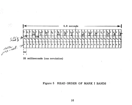
The remaining eight bands are deSignated as slow bands. These bands are taken one at a time on every fourth revolution of the drum until all eight have been read, and then, of course, the process is repeated. Because of this read order, instructions on the fast band are performed every 50 milliseconds, those on the medium-fast bands every 200 milli-seconds, and those on the slow bands every O. 8 seconds.
15
;? <t!,S;
7:.--;'. i;:
v
7
~.As stated previously, two other bands on the drum are being read simultaneously each time a band of the general program is read (that is, on each drum revolution). One of these is the radio-aids band, which is read on every drum revolution, and the other is one of the four linear interpolator bands. The four interpolator bands are read one after the other at the rate of one band per drum revolution. Therefore, any given interpolator band is read once on every fourth revolution of the drum. Figure 5 illustrates the final order in which all the bands on the drum are read. The first line of this illustration represents the general program bands, the second line represents the linear interpolator bands, and the third line represents the radio-aids band. Each vertical column represents one drum revolution (25 milliseconds). After 32 revolutions (0. 8 seconds), all of the bands have been read in the order indicated.
I~
F Hl F
~
F IJ:!2-1F ~F!l-
F~
Fg F
I'"
Dl~
" ' . '1\ D2 D3 D2 D3 D4 D1 v2 D3 D4 1\
7
I1 R R R R R R-
R R R R R R• I
...,.:
• I• 1
25 milliseconds (one revolution)
0.8 seconds p
I~
F I~ F ~~ F.;l
" ., , D2 U3 D4 1\ D~ D3 R R R ~ R' R
~
D4
R
F
I~
If
I~
F}\
FD1 D2 D3 P4 1\ D2 D3
R R R, II R R R
Figure 5 READ ORDER OF MARK I BANDS
16
!~
F '}~ F~
I-c,> " . 1-D4 ~ D2 D3 D~
R R R R R
o
o
[image:18.612.11.554.329.764.2]•
o
" /
3. 3 CORE MEMORY
...
:--The core memory of the M~k I is a 2048-word, random-access memory, each of whose 2048 words is an addressable location. Numerical information may be stored in any word location, or,
converse-ly, the information contained in any word location may be read out on A 4? VVi,,~,6L;;;.
command. Only one word location in the core may be read out of or writ- j!(fi,. ":k4
ten into during any given machine operation cycle (6 microseconds). Each word of the main core is 24 bits long, of which the most significant bit is the sign bit.
It is the function of the main core memory to act as the working storage of the computer. That is; all quantities stored in the main core can be changed, updated, and erased.
The variables in the simulator equations are each assigned to a specific location in the core storage. As each of these variables is re-calculated or changed, the new value is inserted into the proper core location, thus replaCing the previous value. All inputs to the Mark I computer from the outside world (for example, cockpit, instructor's station) come to preassigned storage locations in the main core. All outputs from the Mark I to the rest of the simulator system are read out from their preassigned storage locations in the main core.
Independent variables to be used by the linear interpolator for the purpose of function generation are also read from their assigned loca-tion in the core memory. Similarly, cPIllPuted funcloca-tional values are stored in assigned core locations b~ tQ.e linear interpolator. In shor~, all mathematical quantities needed for a simulator program are stored in the core memory (with the exception of constants, which may be stored on the drum).
As stated before, only one word of the entire core memory may be interrogated or written into during anyone 6-microsecond period. How-ever, it is apparent that the many parallel processes of the computer (that is, function generation, radio preselection, input-output reading, main pro-gram arithmetic) all require memory access. Hence, it is necessary that these various processes be given a priority rating. In the Mark I, any op-eration of the main program requiring memory access takes priority. Any operations or instructions in the main program that do not require memory access are considered to be "holes" in the main program, and it is during these "holes" that the auxiliary processes of the computer gain access to the core memory. Hence, instructions in the main program such as ~"
Priority for all of the parallel processes of the Mark I is as
follows:
i
j:ecr~~~
/k~~
:1-~
Main program (; j .. .o(~j.k ~J
'P
~'i
ytlY'rrj
3~
Digital function interpolation!--
F (
~-'
r:r~W¥M
ct;v;,
D
F;t'(
Radio aids preselection(D;1;.
(:ZUd.
LJj
__ t)
Ai
Analog input scanning·AI
0
b
4
Analog output readingDIA-l'
7
.-9-V
Boolean input scanning.P
S ()8".x)
Boolean output readingl:>
S
IThe reasons for this particular order of priority will become apparent as the various operations are discussed in detail.
Of the 2048 words of memory in the main core, the first 128 words are reserved for use as Boolean storage locations. Only the first 16 bits in each of the 128 words are used for this purpose. This results in a total of 2048 bits of Boolean storage, since a Boolean word is only one bit long. The core memory, then; is set up to appear as if there were two separate core memory blocks - one being a 2048-word arithmetic core and the other being a 2048":word Boolean core.
Like its counterpart, the arithmetic core memory, the Boolean core memory acts as the working storage for all Boolean opera-tions. Here, Boolean variables are assigned storage locations, Boolean inputs from the rest of the simulator system are read into preassigned storage locations in this memory, and Boolean outputs from the Mark I
to the rest of the simulator system are read out from their assigned storage locations in the Boolean memory.
Since the Boolean core memory is actually made up of 128 words of the main core memory, then any instruction requiring access to the Boolean memory is, in truth, accessing the main core memory. Therefore, any instruction of the main program that requires memory access, whether arithmetic or Boolean, represents a "highest priority" operation.
Because there is no circuitry in the Mark I to prevent hiJ;Il from doing so, it is possible for the programmer to address the entire contents of one of these "blocks" of Boolean storage (the entire 16 bits of one of the
18
<)
o
o
•
128 main-core words) by using an ordinary (non-Boolean) instruction. It
is conceivable that this sort of thing might be deliberately performed in order to provide a direct 16-bit binary output of an ordinary arithmetic quantity without going through the D-A converter. In this case, the main word location containing the 16 bits concerned would be "stolen" perma-nently from the Boolean section for use by the main arithmetic unit. It
should be noted that Boolean storage locations may also be "stolen" (in blocks of 16) for the purpose of storing an externally coded, 16-bit binary word as an input, thus bypassing the A-D converter.
It is important, if these practices are employed for the purpose of providing direct binary inputs and outputs of ordinary arithmetic quan-tities, that the programmer look upon the entire Boolean core as being reduced in size, and never address, the bits concerned for any Boolean purpose.
3. 4 MAIN ARITHMETIC UNIT
The main arithmetic unit of the Mark I acts as the operating center of the computer. This unit consists of 1) a 24-bit accumulator
1 register for holding the numerical results of arithmetic operations, 2)
all of the necessary logic circuitry for performing arithmetic operations and transferring numerical data, and 3) a salvage register that salvages the old contents of the accumulator when a new word is loaded into it.
3. 4. 1 General Organization
All numerical operations in the main arithmetic unit are of the fixed-point, binary form. All numbers handled by the main arithmetic unit, either as inputs to or results of arithmetic operations, are in the form of an absolute value and a sign. Sign processes are performed in all arithmetic operations, and signs are preserved in the results. All number words are 24 bits in length, the first bit being the algebraic sign, and the remaining 23 bits being the absolute value of the binary number.
If
the sign bit is zero, the number is positive. If the sign l>it is one, the number is negative. Thus, a numerical word in the Mark I might be represented as follows:010 0 1 1 0 1 0 1 1 1 0 0 1 0 1 0 1 0 1 1 1 0 0 1
'f "---
~- - - - /
Sign Bit (+) 23 Magnitude Bits
In the Mark I's fixed-point arithmetic, the decimal point is assumed to be to the left of the most significant bit; therefore, the mag-nitude of a number is always less than- one. The largest magmag-nitude that may be represented is .99999 . . • . in decimal notation, or . 1111111 . . . . in binary notation. All numbers handled by the Mark I must be scaled with this fixed-point notation in mind.
If the result of any arithmetic operation in the Mark I is a number whose magnitude is greater than one (that is, greater than
1.11111111 . . .
I),
an automatic overflow process sets each bit of the accu-mulation to "1" but preserves the sign of the result. Thus, after an over-flow caused by a positive result greater than one, the contents of the ac-cumulator will be:01 1 1 1 1 1 1 1 ~ 1 1 1 1 1 1 1 1 1 1 1 1 1 1 1
An automatic overflow is possible in the execution of any of the following instructions: ADD, SUBTRACT, DIVIDE, SCALE.
The rules for addition in the binary number system are as follows:
1 + 1 = 10 (zero with 1 carried)
Ji~ I :.
II
"
As an example of binary addition, the sum of the two numbers 1011001 and 1001010 is:
Carries 1011000
1011001
+ 1001010 10100011
Addition in the Mark I is accomplished by a parallel adder with fast carry propagation. Consider the two binary numbers A and B:
An· .~A1 AO
A
=
O ••• 1 1 1Bn •. · B2 B1 BO
B = O .•. 0 1 1
20
o
o
o
!
o
In a parallel adder, the addition of corresponding bits be-tween two numbers is done simultaneously. That is, in the example shown, the AO digit is being added to the BO digit at the same time that the Ai and Bl digits are being added. Carries, of course, must be con-sidered. When adding the two least significant digits (AO + BO), there is obviously no carry from the right, and the results of ~is addition may
be described as follows: \
AO BO Cout Sum
1 0 0 1
1 1 t 0
o
0 0 0,o
1 0 1,This table (often called a truth table) shows that the sum of AO and BO is one if AO and BO are complementary. Cout denotes carries to the left - that is, to the next pair of digits, Al and Bl. If AO and BO are both zero, thEm the sum is zero and there is no carry. If AO and BO are both one, the sum is zero and a "1" is carried.
The sum of any succeeding pairs of digits of A and B is made more complicated by the fact that carries from the right must be con-sidered. Examine the following truth table and consider the conditions that make the sum one:
A B Cin Cout Sum
0 0 0 0 0
0 0 1 0 1
1 1 0 1 0
1 1 1 1 1
0 1 0 0 1
0 1 1 1 0
1 0 0 0 1
1 0 1· 1 0
This table is perfectly general in that it represents the sum of any two corresponding bits of any two binary numbers. It will be seen that S and Cout are now determined by the binary addition of three quan-tities: A, B, and Cin. Using Boolean notation, Sand Cout can each be defined by an equation in A, B, and Cin. If these two equations are im-plemented for each pair of corresponding digits of the binary numbers A and B, the resultant system represents a complete parallel binary adder.
3.4.2 The 24-Bit Arithmetic -Accumulator
/;.,£ .
Almost
!:f6o/O
of the instructions for the Mark I cause some operation to be performed on the numerical data contained in the arith-metic accumulator (for example, add, subtract, multiply). It should be stated that only numerical data can ever be inserted intO' the accumulator (that is, instructions are found only on the drum and can never be oper::lted on or modified in any way).
'&;;,,1-The first bit (most significant bit) of the /tccumulator is re-served as a sign bit. This bit gives the algebraic sign of the number de-fined by the remaining 23 bits - "0" for a positive number and" 1" for a negative.
Numerical data may be loaded into the accumulator from the core memory and, by virtue of a special instruction, from the drum. Data contained in the accumulator may be stored only in'the core memory. ~,-'
~-~,;t;;i);~;~ >:l', .-;;;>r·{::{~~.¢i . ..--i'~~:ift.,....~ V'~. ,;.:.r~':yf"'{~'L''k';''''''_
Most operations performed on data in the accumulator re-quire only a very small amount of time and may be initiated and finished _ in the amount of time equal to one machine operation cycle (6.105 micro-seconds). A few of these operations (multiply, divide) require several, machine cycles to complete; hence, once they are initiated, extreme care must be taken that new instructions do not arrive requiring operations on data in the accumulator until the previous,more lengthy, operation has been completed. This point is treated more fully in a subsequent section.
3.4.3 The 24-Bit Salvage Register --{;.'.'
Associated with the arithmetic accumulator is a salvage register, also 24 bits in length. When an instruction is read directing that a word of data from some source be loaded into the accumulator, and there is no salvage register, then whatever word happens to be in the accumulator at that time is lost when the new word is loaded. It is the function of the salvage register, just as the name implies, to salvage the data word in the accumulator just before a LOAD instruction. Hence,
if the number X is in the accumulator at the time that an instruction is read directing that Y be loaded into the accumulator, then one machine
22
o
o
o
)
cycle later, Y will appear in the accumulator and X will appear in the salvage register. The previous contents of the salvage register will be
lost.
The salvage register is an addressable location~ That is, it may act as a source of data with which to perform arithmetic opera-tions on the contents of the accumulator. The contents of the salvage register, however, may not be loaded into the accumulator.
3. 5 BOOLEAN ARITHMETIC UNIT
The Boolean arithmetic unit is the Boolean counterpart of the main arithmetic unit. This unit performs all Boolean operations indicat-ed by instructions in the general program. Thus, the logic circuitry of the Boolean arithmetic unit is arranged to perform the functions of AND, OR, COMPLEMENT, LOAD, and STORE. Like its counterpart, the main arithmetic unit, the Boolean arithmetic unit has an accumulator and a salvage register. Since Boolean words are one bit in length, tlie Boolean accumulator, which is used to hold the results of all Boolean operations, is a one-bit register. Boolean words may be loaded into the Boolean ac-cumulator from the core memory, and information in the Boolean accumu-lator may be stored in memory locations in the Boolean portion of the main core. All Boolean operations, indicated by instructions in the general pro-gram, are performed on the contents of the Boolean accumulator by the contents of the address specified in the instruction.
The Boolean salvage register performs the same, function as the salvage register of the main arithmetic unit (that is, it salvages the old contents of the accumulator when a new word is loaded). However, unlike the main arithmetic salvage register, which is only a one-word register, the Boolean salvage register can hold four one-bit words, all of which are addressable. Because of this multiword capacity, the Boolean salvage register may act as an intermediate, temporary storage unit, thus re-ducing the core memory access requirements of the Boolean arithmetic unit. The operation of the salvage register is shown in Figure 6, assu-ming a hypothetical series of LOAD instructions.
Since the four words of the Boolean salvage register are ad-dressable locations, the contents of any of these word locations may be used to perform a logical AND or OR with the contents of th~ Boolean accumulator. However, the contents of any of these salvage register locations may not be loaded into the Boolean accumulator. Neither may the contents of these locations be stored in the Boolean core. Only the contents of the accumulator may be stored in the core memory.
CONTENTS OF Boolean Sa1vase Re&!ster
1
01
11
21
31
INSTRUCTION ACCUMULATOR~
I I
Load b
~
I
a
I
Load c
8
I
b aI
Load d
~
I
cI
bI
aI
I
Load e
B
I
dI
cI
bI
aJ
Load f
~
I
eJ
dI
cI
bFigure 6 OPERATION OF BOOLEAN SALVAGE REGISTER
3.6 LINEAR FUNCTION INTERPOLATOR
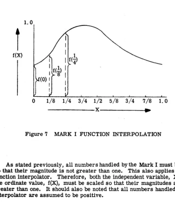
Function generation in the Mark I is done continuously in parallel with the main program of the machine, and thus, because of computation time saved in the main program, contributes largely to the real-time dy-namic response of the computer. Function generation is accomplished by means of linear interpolation between the ordinates of fixed breakpoints. Figure 7 illustrates an arbitrary function of X whose X axis has been divided into eight equal segments. These eight segments are defined by nine breakpoints: 0, 1/8, 1/4, 3/8, 1/2, 5/8, 3/4, 7/8, and 1.
If the ordinates of these nine breakpoints are known [f(O), f(1/8), f(1/4), f(3/8), and so forth] and if the independent variable X is known, then it is possible to perform a linear interpolation to determine f(X). For instance, if X lies between 1/8 and 1/4, then it is possible to inter-polate between f(1/8) and f(1/4) to obtain a very close approximation of f(X). The linear interpolator has its own arithmetic unit with a parallel binary adder and appropriate registers and logic circuitry to' solve the linear interpolation formula for f(X).
24
0
0
o
I
I
[image:26.612.121.490.101.375.2]o
1.0
f(X)
o
1/8 1/4 3/4 1/2 5/8 3/4 7/8 1. 0---x---~~~
Figure 7 MARK I FUNCTION INTERPOLATION
As stated previously, all numbers handled by the Mark I must
bescaled
so that their magnitude is not greater than one. This also applies to the
function interpolator. Therefore, both the independent variable, X, and
the ordinate value, f(X), must be scaled so that their magnitudes are not
greater than one.
Itshould also be noted that all numbers handled by the
interpolator are assumed to be positive.
The four bands on the magnetic drum used for function interpolation
store the breakpoint ordinates of all the function curves. Also, the drum
contains the core memory location of the independent variable and the core
memory location in which,the calculated value of the function will
bestored.
Each different function is represented by its own block of information listed
on one of the bands, all of the blocks being listed in order around the bands.
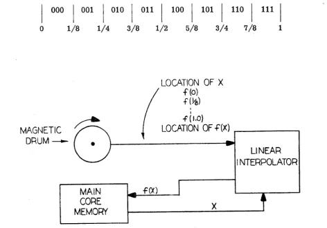
Figure 8 shows the flow of information for function generation.
It is unnecessary to store the X values of the breakpoints, since these
breakpoints are fixed at 0, 1/8, 1/4, and so forth.
Itis only necessary to
build a logic of the interpolator in such a way that it can inspect the value
of X and recognize which two breakpoints
itlies between. Consider the
binary representation of the fixed breakpoints:
'0
= •
00000000. • • • •
1/8
= •
00100000. • • • •
[image:27.611.98.456.80.494.2]1/4:: .01000000. 3/8
=
.01100000 •. 1/2= •
1000000 •. 5/8 = • 1010000 •. 3/4 = .1100000 •• 7/8 = .1110000 . .1 = .111111111111111111111. •••••••
It is apparent from these representations that the first three digits of X will determine which two breakpoints X lies between, in accordance with the following scheme:
000
I
001I
010I
011I
100I
101I
110I
111I
o
1/8 1/4 3/8 1/2 5/8 3/4 7/8 1MAGNETIC
DRUM~
MAIN
CORE
MEMORY
f(X)
LOCATION OF X
f(o) f(~)
I I
-f (I.o)
LOCATION
OF
-F(X) . . -_ _ _
---.
X
LINEAR
[image:28.611.77.550.336.666.2]INTERPOLATOR
Figure 8 FUNCTION GENERATION FLOW DIAGRAM
26
- - -
-0
1
!
I
tio
o
o
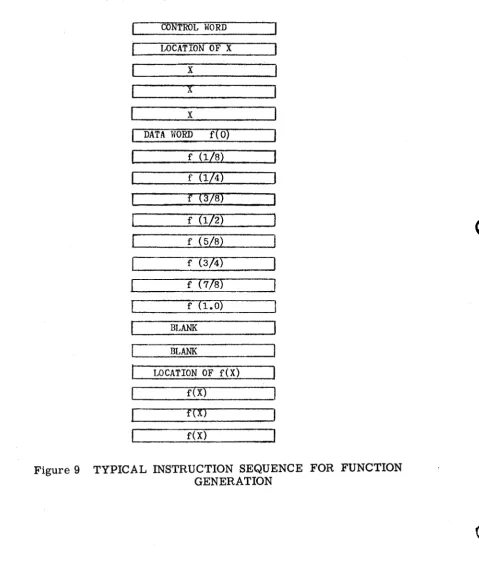
Looking at a block of words on the drum concerning a given function
(assume a function of a single variable), the first word listed is a control
word that serves to identify a new function and tell whether it is a function
of one, two, or three variables. The second word listed is the memory
location of the independent variable. Following this will be the ordinates
of the nine breakpoints in order, beginning with f(O). Notice that the
memory location of X, the independent variable, is listed before the
ordi-nate information. It will be remembered that memory access by the main
program has priority over access requirements by the interpolator.
There-fore, the interpolator may only have access to memory during "holes" in
the main program.
In
order to ensure that the current value of the
inde-pendent variable is obtained from its memory location, its address must
be repeated several times. Thus, the first time the address of X is read
from the drum, the interpolator will attempt to interrogate the core
mem-ory.
If itfails to do so during the read cycle (6.105 microseconds),
an-other word will be read directing it to interrogate the memory again. By
repeating this process a sufficient number of times, the probability of
en-countering a "hole" in the main program, and thereby gaining access to the
core memory, can be increased to the point where access is practically
en-sured.
Inmost cases, repeating the location of the independent variable
four or five times will prove sufficient.
Once access to the core memory has been gained, the current value
of the independent variable is read into a register in the interpolator.
Here, as stated previously, the first three digits of X"(the independent
variable) are examined to bracket X between two brea.li:points. This
proc-ess is finished before the data field is read; therefore, before the first
ordinate is read, the interpolator already knows which two breakpoints
brack,et X. As the ordinates are read from the drum, only the two
ordi-nates concerned are held for interpolation. The other ordinate words are
ignored
bythe interpolator.
The result of the iilterpolation is, of course, f(X). This value is held
in the linear interpolator until a word is' read from the drum directing that
f(X) be stored and giving the location in the core memory in which it is to
be
stored. As before, when the location of X was repeated several times
in order to ensure memory access, the location of f(X) must be repeated
several times. Again, four or five repetitions of the location of f(X) are
sufficient in most cases.
In
the event that X were located between 7/8 and 1.0, the interpolator
would have to wait until the eighth and ninth ordinates were read from the
drum before
itcould begin its calculations. Thus, this means that some
Ume must be allowed after the last ordinate is listed before the memory
location of f(X) is listed. This time is to allow the interpolator to finish
its calculations before directing it to store -the results. In the case of a
single-variable function, two blank words (12 microseconds) are sufficient.
In the case of a function of two variables, four blanks are required, and for the three-variable function, six blanks are required.
[image:30.611.88.568.165.735.2]The final arrangement of the data and instructions for some single variable function, f(X), might be as shown in Figure 9.
Figure 9 TYPICAL INSTRUCTION SEQUENCE FOR FUNCTION
GENERATION
28
-=---~----
...
"""""'====,--- - - - = - - - ---~o
o
o
0
1
I
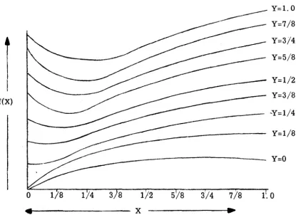
In order to handle a function of two variables in the Mark I, the func-tion must first be represented in the form of a "family" of nine single-variable functions, as shown in Figure 10.
Y=1. 0 Y=7/8 Y=3!4 Y=5/8
Y=1/2
f(X) Y=3/8
o
3 8 5;83/4
••
~---X
7/8
..
,Y=1/4
Y=1/8
y=o
1.0
Figure 10 REPRESENTATION OF FUNCTION OF TWO VARIABLES
Examination of this figure shows that 81 ordinates are required to describe the function. The address of Y is listed after listing the address of X, and this address, also, must be repeated several times for memory access. Then the 81 data points are listed in order, beginning with the f(X, Y=O) curve and ending with the f(X, Y=1. 0) curve.
Going a step further, a function of three variables would be composed of nine "sheets" such as the one shown in Figure 10. In this case, there would be a total of 729 (9 x 9 x 9) words of data to be listed for the function interpolation. The location of the Z independent variable would be listed after the Y location, and,like the X and Y variables, would have to be list-ed several times to ensure memory access.
[image:31.616.74.489.176.478.2]•
Since it is possible to list 4096 words around a single band of the drum, and since there are four bands reserv~d for the linear interpolator, there is a total of 16,384 words of storage capacity on the drum to be used for function generation alone. Referring back to Figure 9, it can be seen that approximately 22 words are required in order to program the gen-eration of one function of a single variable. Hence, if only singh~-variable functions were stored on the drum, there would be sufficient capacity to generate over 740 different functions. If functions of two or three vari-ables are stored, of course, the capacity is affected accordingly.
To provide for maximum use of the capacity available, the linear inter-polator of the Mark I is constructed so that, by using certain indexing bits in the control word, it is possible to use the same function data or curve with four different independent variables, with the results stored in four different locations. The programmer can, for example, instruct the inter-polator to index through the same set of engine function curves with four different sets of variables representing four different engines on an air-craft. The purpose of this is to reduce the necessity for having to repeat the data for the same curve several times on the drum, thereby saving storage capacity on the drum. The penalty is that the functions are calcu-lated at only one-fourth of the normal rate - that is, non-indexed functions are recalculated four times as frequently as indexed functions. Since the four bands on the drum read at the rate of one band per drum revolution, and since one drum revolution requires 25 milliseconds, all four bands are read and every function listed is calculated every 100 milliseconds. In other words, the normal rate of recalculation for non-indexed functions is 10 times per second, and that for indexed functions is 2.5 times per second.
All of the words on the four bands of drum storage for the linear inter-polator are 11 bits long. One of these 11 bits (the most Significant) is re-served as a control bit and the remaining ten are for data. Therefore, numerical data (ordinates of the breakpoints) are listed with only ten-binary-digit resolution. Arithmetic in the interpolator, however, is c.arried to 14 places and rounded off.
3.7 RADIO AIDS PRESELECTOR
3.7. 1 Introduction
Each transmitter located anywhere in the world causes a signal to be introduced into the antenna of every receiver in the world. Certainly, the signals induced by very distant transmitters are extreme-ly weak and cannot be heard because of the noise level. Others are re-jected by the frequency-selection circuits of the receiver. This
state-30
o
o
o
o
ment applies particularly well to radio navigation facilities, because navigation transmitters which occupy the same frequency band have de-liberately been separated by a large distance, or made to operate with a low power output, or confined by a narrow radiation pattern, in order to prevent interference. These facts make it possible to devise an auto-matic radio navigation simulation system which, on a basis of receiver frequency and aircraft location, can select for each receiver the one best facility to receive.
It is the function of the Mark I radio aids preselector to examine a total of 350 different radio transmitters and select the one transmitter, if any, that each of the simulated aircraft receivers should be picking up. This process operates in parallel with the general program of the Mark I and is completely automatic, without need for programmer attention.
In the Mark I radio-aids system, the information required for the simulation of 350 navigation transmitters is contained in a band of 20 data tracks of the Mark 1's program drum. These tracks are used independently of the main program and linear interpolator tracks, and are used in a read-only mode. The method for loading data into these 20 tracks is identical to that used for loading the program and interpolator data into the magnetic drum. A new set of facilities can be entered by means of the photoelectric tape reader in about a minute's time, although it is necessary to interrupt the simulated flight during the loading operation.
The signal feature of the Mark I's automatic radio-aids system is that it treats each transmitter as a separate entity. Under this con-cept, an ILS facility would consist of a localizer transmitter, two 75-megacycle marker transmitters, and two low-frequency compass-marker transmitters, for a total of five separate units. Each simulated transmitter is counted separately, with the following exceptions:
1) The glideslope facility is provided as a component of the localizer system and does not require a separate transmitter in the total facilities count.
2) A DMET system installed at a VOR station, or a tacan DME system, is, from a computational standpoint, an integral part of the azimuth transmission facility and does not count in the total.
With the exception of these two types of facilities, each individual trans-mitter counts as a separate unit. Thus, Z markers and fan markers associated with an A/N range station are totaled individually.
3.7. 2 Classification of Facilities
The 350 available transmitters are divided into five groups, according to the type of facility. The maximum number of facilities in each of the groups may not be exceeded, although it is not necessary that all facility channels be employed if a smaller amount is desirable. The groups are:
1) Low-Frequency Transmitters - This group includes low-frequency beacons, low-frequency compass locator faCilities, and A/N range stations. A total of 127 such facilities can be represented, of which as many as 32 may be A/N range stations - although it is not necessary that all 32 be so assigned.
2) VHF/UHF Transmission Facilities - These include VOR transmitters, tacan transmitters, Navy UHF direction-finder trans-mitters, and ILS transmitters. A total of 127 independent VHF/UHF transmitters can be represented.
3) outer ILS markers.
Outer ILS Markers - The system can represent 32
~
4) Middle ILS Markers - The system can represent 32
middle ILS markers.
~-5) Fan and Z Markers - The system is capable of repre-senting 32 fan or Z markers, which can be intermixed in any desired pro-portion.
These facilities can be received when within range and if the appropriate receivers are operative and tuned..
It should be noted that the Mark I radio-aids system does not automatically provide the voice signals associated with certain facilities -that is,it is left to the instructor to provide this in the usual manner. The prime reason for omitting this feature is that of excessive cost in relation to training value. Call letter identification is, of course, provided for the facilities and is deemed to be quite adequate for training purposes.
3.7.3 Facility Selection 3.7.3.1 General Considerations
Facility selection is based upon electronic inspection of the data words provided for each of the facilities. The preselector system employs specialized electronic circuitry to scan the drum data concern-ing the 350 individual navigational transmitters and select the one eligible transmitter facility for each naVigation receiver in the aircraft. Since
o
o
all 350 facilities must be scanned every drum revolution (40 times per
0
32