DESIGNING OF SINGLE ENDED PRIMARY INDUCTANCE CONVERTER FOR
SOLAR PV APPLICATION USING ARDUINO CONTROLLER
1,2,3,4 Student, Dept. of Electrical and Electronics Engineering, Knowledge Institute of Technology, Tamilnadu, India 5II-Year-M.E-Embedded System Technologies, Knowledge Institute of Technology, Tamilnadu, India 6Assistant Professor, Dept. of Electrical and Electronics Engineering, Knowledge Institute of Technology,
Tamilnadu, India
---***---
Abstract-
This paper presents the designing and modeling of SEPIC (Single Ended Primary Inductance Converter) DC-DC converter for photovoltaic applications. A solar panel output will vary with respect to solar radiation and this radiation is less which does not meet the requirements of the load. So we proposed SEPIC converter which acts as a step up or step down transformer to boost the voltage based on solar radiation level and it also acts as an impedance matcher and regulator between the source and the load since the output from the solar panel is unregulated. The limitations such as inverted output voltage, high electric stress on converter elements and pulsating input current are resolved by the proposed converter. An incremental Conductance(IC) algorithm is used for better Maximum Power Point Tracking (MPPT) in the proposed system. Sinusoidal Pulse Width Modulation (SPWM) type of inverter module is employed to convert DC voltage into AC voltage for AC load applications. The effectiveness of the proposed system is demonstrated in simulation using MATLAB/SIMULINK environment .The practical system was tested up to 15V solar panel, 12V lead acid battery 24V sepic converter module and 230V inverter.Keywords: Solar Panel1, SEPIC converter2,
Incremental Conductance3, SPWM type inverter4, MATLAB/SIMULINK5.
1. INTRODUCTION
Solar energy is the one of the most promising and attractive energy sources for the present and future generations. Solar is most preferred energy sources as it is abundant and non-polluting in nature. Because of these endless advantages, solar photovoltaic energy has gained recognition as an alternative source of energy. However, the radiation of sun will not be same all the time and also the output voltage of the solar panel directly depends on intensity of the radiation. Due to this, the output voltage of the PV panel will vary accordingly to the incidence of radiation. In order to overcome this, converters are used between the solar panel and the load to maintain the output voltage constant. There are different types of converters such as buck, boost, buck- boost, Cuk and SEPIC
converter. The buck converters can only step down the voltage, the boost converters can only step up the voltage and the buck-boost, Cuk and SEPIC converters can either step up or step down the voltage. The Cuk and buck-boost converter operation cause huge amounts of electrical stress on the components, this can result in failure of device or overheating. The voltage from the solar panel is maintained as constant by using converter and the inverter is employed to convert DC output of the converter into AC. The single-ended primary-inductor converter (SEPIC) is a type of DC/DC converter which enable the voltage at its output to be greater than, less than, or equal to that at its input. The output of the SEPIC can be controlled by the duty cycle. The buck-boost converter provides negative regulated output voltage whereas the SEPIC converter provides positive regulated output voltage for the given input voltage.
2. LITERATURE REVIEW
Among the non-conventional or Renewable Energy Sources (RES), solar energy is an important source of energy. Solar techniques are characterized as active and passive. Active techniques include PV and solar thermal collectors and the passive techniques include solar roof-top building. Due to the advantages like absence of fuel cost, less maintenance and pollution free energy production this system is gaining more importance than other systems [1]. Various techniques for efficient extraction of the maximum output power from a solar panel under varying meteorological conditions have been studied. Among these mechanisms, the Maximum Power Point Tracking is most trustworthy and it is best suited for PV system. The use of DC-DC converter in between the grid and PV module can provide efficiency optimization [2]. The main difference between the P&O technique and other technique is that the output power of PV array is used directly for the control of dc/dc converter thus reducing the complexity of the system. The resulting system has high efficiency, low cost and can be easily modified [3]. Even though the use of sensors/controllers with every module does not seem to be a major issue today considering the many applications involving extensive
diagnostics of the PV modules, yet there is certainly a scope for further optimization of their numbers. However, this may not be an issue for smaller system, but this may be an issue for large systems, where auxiliary power support may be required [4,5]. The converters such as buck, boost, buck-boost, cuk converters are being used in MPPT systems. PWM inverters are used for grid interconnection and standalone AC loads. The selection of converter depends on the load connected to the system. The ripples in dc voltage and current also influence the selection of converters. With the above mentioned converters and MPPT algorithms, solar panels can be configured to feed any kind of load [6].
The above mentioned converters can also produce stepped up or stepped down the solar voltage, but the output voltage polarity is inversed with respect to input. Besides, those converters will produce ripple current.
3.PROPOSED METHODOLOGY
3.1. BLOCK DIAGRAM OF THE PROPOSED SYSTEM
The proposed system employs SEPIC converter instead of buck-boost converter for better voltage profile. The output generated by the solar panel is given to the battery for storage purpose. The voltage from the battery is given to the sepic converter which either steps up or steps down the voltage of solar panel for the requirement of load. The efficiency of power transfer from the solar panel is influenced by the amount of sunlight falling on the solar panels and the electrical characteristics of the load.
Fig.1 Block Diagram
The output from the sepic converter is given to the Sinusoidal Pulse Width Modulation inverter which is used to convert dc voltage from the sepic converter to the ac voltage for the purpose of driving an ac load. In the proposed system Incremental conductance technique is used for MPPT tracking. This MPPT controller is used to track the maximum current and voltage of the converter. This system is preferred than existing system since it reduce ripple current and will produce non-inverted output voltage.
3.2. SEPIC CONVERTER
The SEPIC converter design works in the continuous conduction mode that means the current through the inductor L1 and inductor L2 never reaches zero. The output voltage may be lower or higher than the input voltage. In this circuit the capacitor C1 isolates the input from output and provides the protection against the short circuit. Among all dc-dc converters, SEPIC converter is used in continuous current conduction (CCM) mode. In this, the PWM switching is done at the frequency of 50 kHz, where reference current obtained from MPPT algorithm is compared with inductor current. Then the error signal is treated as control signal which is compared by repetitive waveform and the switching pulse is obtained.
Design of sepic converter
Duty Cycle Calculation:The voltage value of the sepic
converter increases or decreases depends onthe duty cycle of switches and active elements in the circuits. The output of sepic converter is given by
……… (1)
Then the losses are not taken into the account because of the parasitic elements such as mosfet and diode drop VD. It is given by
………. (2)
………. (3)
When the input voltage is minimum, the value of duty cycle is maximum.so the value of is given by
…………. . (4)
Inductor Selection:To determining the inductance is to
allow peak-to-peak ripple current is approximately 40% of the maximum input current at the minimum input voltage. Then the value of ripple current flowing through the inductor is equal
……… (5)
The inductor value is calculated by
Where switching frequency, is the duty cycle at the minimum V in. The peak current in the inductor is not saturate.so it is given by
……… (7)
If L1 and L2 are wound on the same core, that value of inductance is replaced by 2Ldue to the mutual inductance. So that the inductor is calculated by
….. (8)
Power MOSFET Selection: The selection of the
MOSFET is the minimum threshold voltage Vth (min), gate-drain charge and the maximum drain to source voltage. The peak switch voltage is equal to input and output voltage (Vin+Vout).Then the peak switch current ( is given by
………….. (9)
The RMS current through the switch is given by
√
……… (9)
Where PQ1- the total power dissipation for MOSFETs includes conduction loss and switching loss, IG is the gate driven current. The RDS (ON) value should be selected at maximum operating junction temperature and it is given by MOSFET data sheet.
Input Capacitor Selection: The SEPIC converter has an
inductor at the input. Then the input inductor ensures the low ripple currents. Its produce the continuous and triangular waveform. The RMS current in the capacitor can be expressed as
√ ………. (10)
The input capacitor should be capable of handling the RMS current. The higher value good quality capacitor would prevent the impedance interactions with the input supply.
Output Capacitor Selection: When the power switch
Q1 is ON the inductor is energizing then the output current is supplied by the output capacitor. The RMS current in the output capacitor is given by
√
……… (11)
Diode Selection: It is used handle the peak current
and reverse voltage. In a SEPIC converter the diode peak current is same as the switch peak current The minimum peak reverse voltage is given by
… (12)
During period of operation some power dissipation occurs in the circuits. In this circuit the power
Dissipation of the diode is equal to the output current and it is multiplied by the forwardvoltage drop.
Sepic Coupling Capacitor Selection: The selection of
sepic capacitor is depends on the RMS current, it is given by
√
…………. (13)
…………... (14)
3.3. INCREMENTAL CONDUCTANCE
An MPPT system consists of a voltage divider circuit and Hall-effect current sensor as a current and voltage sensors, a DC–DC converter and a MPPT algorithm. A vital feature of Incremental Conductance algorithm is its high tracking accuracy under sudden changes in solar irradiance. In this algorithm, the current and voltage of the PV module are measured. Incremental conductance and instantaneous conductance are planned. Besides this some comparisons are made in order to determine the direction of duty ratio of the switch gate signal. The mathematical expression of this algorithm is derivative of power with respect to voltage. The flow of MPPT is shown in fig2.
4. RESULT AND DISCUSSION
4.1. SOFTWARE
The simulation diagram and the output of sepic converter is shown in fig3 & fig4
Fig3.Circuit diagram of closed loop SEPIC converter
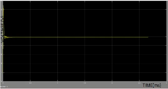
[image:4.612.320.571.102.285.2]From the simulation result it is evident that the SEPIC converter produces non-inverted and regulated output which is ripple free.
Fig. 4.Output of SEPIC converter.
[image:4.612.35.304.557.700.2]4.2. HARDWARE
Fig.5. Hardware SEPIC converter module
The practical system was verified up to 15V solar panel, 12V lead acid battery, and 24V sepic converter module and 230V inverter.
5. CONCLUSION
Both the software and hardware portion has successfully completed and the efficacy of the proposed converter has been successfully simulated in the Matlab/Simulink. From the acquired results, it is evident that, the proposed converter is capable of producing the ripple free non-inverter output with the acceptable efficiency. This converter is designed to boost the voltage from 15V to 24V with the efficiency of 89.52%.
REFERENCES
[1] U.Jagadeesh, K.Lokesh Achari “A Buck-Boost Based Dc/Ac Converter For Residential pv Applications By Using MPPT” Volume-2, Issue-11, Nov.-2014.
[2] Sannasy Mageshwari, S. Kanagalakshmi and Hannumath Rao “Design and Implementation of Buck-Boost Converter for Residential PV Application”, Vol. 3, Issue 12, December 2015.
[3] Noori Bawi Dawood “Review of Different DC to DC Converters Based for Renewable Energy Applications”, IRJET. Volume: 03 Issue: 03 | Mar-2016.
[5] Nor Hanisah Baharudin, Tunku Muhammad Nizar Tunku Mansur, Fairuz Abdul Hamid3, Rosnazri Ali, Muhammad Irwanto Misrun “Topologies of DC-DC Converter in Solar PV Applications” November 2017, ijeecs. Vol. 8, No. 2, November 2017.
[6] J. Dawidziuk “Review and comparison of high efficiency high power boost DC/DC converters for photovoltaic applications”, TECHNICAL SCIENCES Vol. 59, 2011.
[7] G.kranthi Kumar, Ch.Sampath Kumar, D. Kumara Swamy “A DC–DC Boost Converter for Photovoltaic Application”ISSN Volume 8, (September 2013).
[8] Urmimala Chatterjee, Johan Driese, “Intra-Module Dc-Dc Converter: Topology Selection and Analysis” ESAT-ELECTA, 2011.
[9] Annop Nakpina, Sudarat Khwan-ona “A Novel High Step-Up DC-DC Converter for Photovoltaic Applications” iEECON2016.
[10] Hrishikesh Krishna Kumar, Sruthy Sajith,Subha Jacob, Ramya K “Three-level DC-DC Converter with GSS based MPPT for PV Applications” ISSN (IOSR-JEEE),2013.
[11] I.Inayath Bathul, R. Sivasakthi Priya “An Incremental Conductance MPPT Based Sepic
Converter with Battery Charging Unit for Solar PV System”