© 2017, IRJET | Impact Factor value: 5.181 | ISO 9001:2008 Certified Journal
| Page 2336
SEISMIC BEHAVIOUR OF INFILLED FRAME STRUCTURES WITH AND
WITHOUT SHEAR WALL
Geethu Bhanu
1Greeshma A K
21
PG Scholar, Dept of Civil Engineering, SVNCE
2
Asst.Professor, Dept of Civil Engineering, SVNCE
---Abstract -
Reinforced concrete shear walls are used in bare frame building to resist lateral force due to wind and earthquakes. They are usually provided between column lines, in stair wells, lift wells, in shafts that house other utilities. Shear wall provide lateral load resisting by transferring the wind or earthquake load to foundation. Besides, they impart lateral stiffness to the system and also carry gravity loads. But bare frame with shear wall still become economically unattractive. If the structural engineer considered property of the non-structural element in structural design along with other elements like shear wall gives better results. The non-structural element which is already exists in structure but not considered in a structural design as a structural element like curtain wall. The curtain wall means partition wall which is made up of brick masonry therefore it is called as masonry wall and also it is called as an infill wall. If the properties of the infill wall like density and modulus elasticity of brick masonry are considered in structural design, it will helps to improve the strength and stiffness of the structure.Key words: Infilled frame, shear wall, pushover analysis
INTRODUCTION
© 2017, IRJET | Impact Factor value: 5.181 | ISO 9001:2008 Certified Journal
| Page 2337
stiffness of reinforced concrete frame. This attracts part of the lateral seismic shear forces on buildings, thereby reducing the loads on the RC members.NEED FOR THE STUDY
The seismic analysis of RC (Bare frame) structure leads to under estimation of base shear. The underestimation of base shear may lead to the collapse of structure during earthquake shaking. Therefore it is important to consider the infill walls in the seismic analysis of structure. Masonry infill wall and shear wall may contribute remarkably in increasing the stiffness of reinforced concrete frame. The difference in parameters such as maximum storey displacement, storey drift, and base shear should be found out in the case of different models. The better position for shear wall in the infilled frame should be found out by analyzing infilled structure with shear wall at different positions.
Building description
Type Public building
Zone III
Importance factor 1
Height 31m
Ground storey height 4m
Floor to floor height 3m
Depth of slab 150mm
Size of column 700x350mm
Size of beam 600x230mm
Size of infill 360x230mm
Size of shear wall 3000x200mm
LL on floor 4kN/m2
© 2017, IRJET | Impact Factor value: 5.181 | ISO 9001:2008 Certified Journal
| Page 2338
SCOPEThe present study deals with nonlinear static pushover analysis of infilled frame structure with and without shear wall using the software ETABS, in order to find various parameters such as displacement, drift, and base shear for finding the more suitable structure and also the better position of shear wall in the infilled structure.
OBJECTIVES
To study the performance of infilled frame structure with and without shear wall.
To study various parameters such as displacement, drift, and base shear of the structure.
To identify the better position of the shear wall in infilled frame structure.
Compare the results to identify best structural configuration
METHODOLOGY
Literature survey
Modeling of structures
Assigning material properties
Assigning load cases
Pushover analysis
Comparison of results
© 2017, IRJET | Impact Factor value: 5.181 | ISO 9001:2008 Certified Journal
| Page 2339
Material propertiesThe materials include M20 concrete, Fe 415 steel and masonry infill. The density and modulus of elasticity of concrete and masonry infill are given as per standard value.
Concrete
Weight per unit volume = 25kN/m3 Poisson ratio = 0.2
Modulus of elasticity = 22360.68Mpa
Masonry
Weight per unit volume = 21.2068kN/m3 Poisson ratio = 0.2
Modulus of elasticity = 36x105Mpa
Fig.1 3D view of infilled frame
© 2017, IRJET | Impact Factor value: 5.181 | ISO 9001:2008 Certified Journal
| Page 2340
Fig.3 3D view of infilled frame with one wall on each side at middleRESULTS AND DISCUSSION
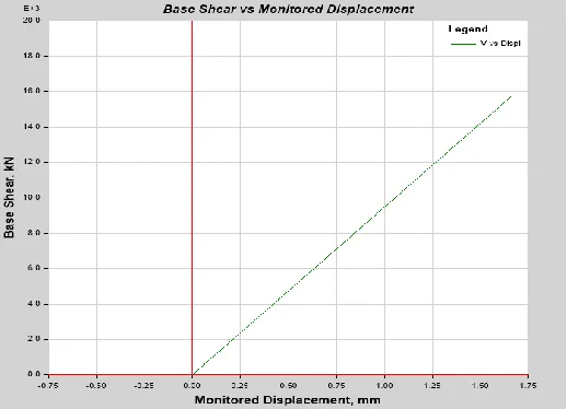
Fig. 4 Pushover curve in infilled frame with one wall on each side at middle
[image:5.612.177.436.358.545.2]© 2017, IRJET | Impact Factor value: 5.181 | ISO 9001:2008 Certified Journal
| Page 2341
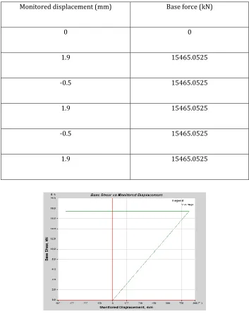
Table 1 Base force Vs monitored displacement of infilled frame with one wall on each side at middleMonitored displacement (mm) Base force (kN)
0 0
1.9 15465.0525
-0.5 15465.0525
1.9 15465.0525
-0.5 15465.0525
[image:6.612.129.482.116.561.2]1.9 15465.0525
© 2017, IRJET | Impact Factor value: 5.181 | ISO 9001:2008 Certified Journal
| Page 2342
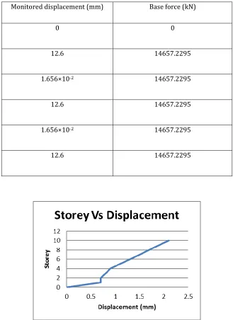
Table 2 Base force Vs monitored displacement of bare frame with one wall on each side at middleMonitored displacement (mm) Base force (kN)
0 0
12.6 14657.2295
1.656×10⁻² 14657.2295
12.6 14657.2295
1.656×10⁻² 14657.2295
12.6 14657.2295
© 2017, IRJET | Impact Factor value: 5.181 | ISO 9001:2008 Certified Journal
| Page 2343
Fig.7 Maximum storey displacement in infilled frame with corner shear wallFig.8 Maximum storey drift in infilled frame with corner shear wall
Fig.9 Maximum storey drift in infilled frame with one wall on each side at middle
© 2017, IRJET | Impact Factor value: 5.181 | ISO 9001:2008 Certified Journal
| Page 2344
Model Base shear (kN )
Bare frame 12869.47
Infilled frame 13967.02
Bare frame with corner shear wall
16955.06
Infilled frame with corner shear wall
16955.07
Bare frame with one wall on each side at middle
14657.22
Infilled frame with one wall on each side at middle
15465.05
CONCLUSIONS
The nonlinear static pushover analysis of infilled frame structure with and without shear wall is considered for finding various parameters such as displacement, drift, and base shear. Four types of structures are considered for analysis. They are bare frame, infilled frame, bare frame with corner shear wall, infilled frame with corner shear wall, bare frame with one wall on each side at middle and infilled frame with one wall on each side at middle. The base shear of bare frame with corner shear wall and infilled frame with corner shear wall is maximum and approximately equal. Among the structures infilled frame with corner shear wall shows less displacement and drift than that of others. From this it is clear that the better position for shear wall is the corner.
REFERENCES
1.Bruneau, M and Bhagwagar, T (2002) Seismic retrofit of flexible steel frame using thin infill panels, Engineering Structures, 24,443-453.
2.Decanini, L, Mollaioli, F, Mura, A and Saragoni (2004) Seismic performance of masonry infilled RC frames, 13th World
Conference on Earthquake Engineering, 4, 1-30.
3.Dinar, Y, Alam, N and Paul, S.V (2013) Performance based analysis of RC building consisting shear wall and varying infill percentage, European Academic Research,1, 2286-4822.
4.Govalkar, V, Salunke P.J and Gore N.G (2014) Analysis of RC frames with shear wall, International Journal of Recent
Technology and Engineering.3,67-72
5.Haris, I and Hortobagyi, Z (2012) Different FEM models of RC frame stiffened by infill masonry for lateral loads, Periodica polytechnic, 2, 25-34.
6.Tamboli, H.R and Karadi, U.N (2012) Seismic analysis of RC frame with and without masonry infill walls, Indian Journal of Natural Sciences, 3, 0976-0997.