© 2017, IRJET | Impact Factor value: 5.181 | ISO 9001:2008 Certified Journal | Page 2152
An Overview on Future Electric Steering System: A Project Approach
Mr.Vishal Chahare
1, Miss. Indira Mhaisne
2, Dnyaneshwar Dongre
31
Assistant professor, Department of Mechanical Engineering,
Deogiri Institute of Engineering and Management studies, Maharashtra, India.
2
Assistant professor, Department of Mechanical Engineering,
Bhivarabai Sawant College of Engineering and Research & Polytechnic, Maharashtra, India.
3
UG student, Department of Mechanical Engineering,
Deogiri Institute of Engineering and Management studies, Maharashtra, India.
---***---Abstract – In today’s world, safe operation of the vehicle
demands that the operator be able to maintain absolute control of the vehicle’s critical operating dynamics: (1) Control of the direction of motion of the vehicle (steering) (2) Control of the velocity of the vehicle, i.e. the ability to slow and fully stop the vehicle (braking). This paper provides an overview of electric assisted vehicular steering including brief description of various conventional systems and the basics of steering; particular attention in addressed to ―Electric Power Assisted Steering (EPAS). Electric power assisted steering has temped automotive engineer since the 1950. Even so, the promise of smaller, lighter, and more efficient systems never quite matched the low cost and performance of hydraulic power assisted steering (HYPAS) advance in microelectronics; however have rekindled interest in EPAS. Motor drive stages, electronic control units and torque sensor can now be manufactured relatively cheaply. These components, coupled with complex control algorithms implemented in software can rival or better the performance and functionality of conventional hydraulic steering systems.
Key Words: Need of EPAS, Future Steering Systems,
System Structures of Safe Electrical Steering Systems, Electric Power Assisted Steering, Components of EPAS, Selection of Materials, Specifications of Components, Cost Estimation.
1. INTRODUCTION
The steering system of an automobile serves two main functions: firstly it allows the driver to make the vehicle follow a desired path or trajectory without requiring excessive physical effort and secondly it assists the driver to judge the driving conditions by allowing some feedback. The later is a subtle aspect of steering system with the driver in the feedback loop striving to minimize the error which the vehicle may have from the desired path.
The electric power steering, EPS, does not have any belt-driven steering pump constantly running, so it is lightweight and the motor consumes energy only when the steering wheel is turned by the driver, and this leads to improvement in fuel efficiency. Also, the elimination of a belt-driven pump
[image:1.595.319.553.320.535.2]and its accessories greatly simplifies manufacturing and maintenance. While offering these benefits, as it does not contain any steering oil, the environment is not polluted both when the steering system is produced and discarded.
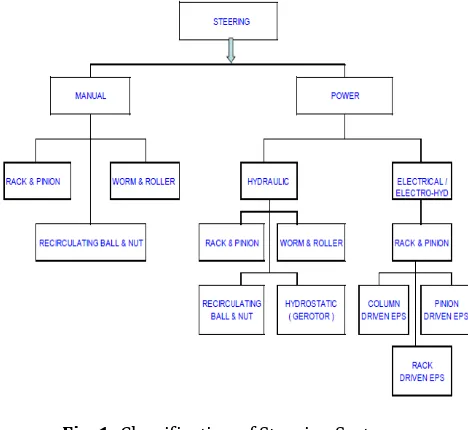
[image:1.595.311.522.549.751.2]Fig. 1: Classification of Steering System
© 2017, IRJET | Impact Factor value: 5.181 | ISO 9001:2008 Certified Journal | Page 2153 Output torque = Steering force (manual torque) + Assist
torque
2. LITERATURE REVIEW
[1] Steve F. et.al. (2014) proposed the estimation of the steering rack force with real-time capable algorithms. First, a non-linear dynamic 4-mass model is given and validated by a prototype EPS. Second, an algorithm for steering rack force estimation is introduced using a non-linear friction compensation module and a linear disturbance observer. Finally, the estimation algorithm is analyzed by means of validated numerical EPS model, a steering test bench and a real prototype car. The results state the excellent performance of the estimation algorithm, even under real operation conditions.
[2] Muhammad K. et.al. (2015) designed the electric golf cart of LIPI traditionally without calculating geometric and kinematic properties of it steering layout. Furthermore, it resulting less quality of handling and make it less safe to operate. The kinematics calculation of steering linkages has been explained by Ackerman. So, this paper’s purpose is to calculate and make recommendation for electric golf cart of LIPI as a solution for improving the handling quality. The result is that maximum turning angle of the car is limited by 30º and the car has R at 372 cm. This is an ideal value according to Ackerman calculation.
[3] Fan C. et.al. (2011) introduced the basic composition of the electric power steering system, and put forward the reasonable design solutions of the soft hardware and the correction methods of controller, given the main technology index of the controller. According to the performance requirements of cars steering system, make the relevant control strategy of the electric power steering system and through the design of related software and hardware to realize this control strategy and it can control each link of the automobile steering process. In order to verify the feasibility of the control strategy, comparison experiments are carried out on a vehicle equipped with the developed EPS and the imported EPS, respectively. The results indicate that the developed EPS has similar performance with the imported one. The developed EPS not only works smoothly, but also has proper steering performance, thus can be equipped on passenger cars.
[4] Hassan M.K.et.al. (2012) discussed the implementation of GA-PID algorithm to realize the potential of energy reduction as compared to conventional PID method. A brushes DC motor is mounted on the steering column to provide an assist torque to the driver. This type of configuration is known as C-type EPAS system. The results have shown that GA-PID controller is able to reduce the energy consumption as compared to PID controller.
[5] Weidong Z. et.al. (2011) proposed a design of AC electric steering system test bench. The paper introduced the bench structure, working principal and main component selection first, and then given implementation scheme of test bench’s three functions: simulation of the road resistance, power assistant control and data acquisition. The test result showed the feasibility of test bench.
[6] Hao C.et.al. (2011) developed EPS boost curve embody into the assist characteristics, improving steer portability and stability. A model for the EPS system has been established, including full vehicle mechanical system, EPS mechanical system, and EPS electric control system. Based on this model, a straight line boost curve was designed and evaluated in this environment to improve the performance of EPS system. Results showed that EPS system with the designed boost curve reduced reacting time and overshoot value, thus ensure the dynamic reaction and stability.
3. NEED OF EPAS
Design options are one of the biggest advantages to the electric power steering. With no pump, mounting bracket, hose or pulley or belt, a lot of under-hood space is liberated for other uses, especially when the servo motor is mounted on the column inside the car. The control unit can be, mounted anywhere on the vehicle, and it can vary the boost level infinitely over a wider range of conditions. Boost level can even become a driver-adjustable feature, and of course boost is available even when engine isn‘t running. The control unit needs a lot of data though, and the power requirement has an impact on the battery and charging system design. Also, the steering wheel torque sensor is a very sophisticated new device which means it’s relatively early in its development and therefore, expensive. But when u think about all the hydraulic stuff you don‘t need for steering, the trade-off is quite acceptable from the engineering, service and environmental point of view.
© 2017, IRJET | Impact Factor value: 5.181 | ISO 9001:2008 Certified Journal | Page 2154 down to the smaller, less expensive cars. Aside from the
Acura NSX, electric power steering technology most likely will start from the bottom a move up to the larger, more expensive cars. Two basic reasons are cited for this. First, larger, heavier cars require more power to turn the steering wheel, and more expensive rack-mounted-motor design are more suitable for the smaller application. Second, according to an SAE paper written by Dominke Peter and Ruck Gerhard of ZF Lensysteme (Steering system) in Germany, the present generation of electric steering boost can’t deliver the feel and handling qualities that driver‘s expect in larger, heavier cars, which in their country mean expensive cars. A good answer to both these problems lies in another new technology that Delphi and others say is just around the corner: the 42-volt electrical system. Regardless of how an electric steering is configured, current draw would be very high, more than most of today‘s electrical system can provide for any length of time. All the world‘s major supplier of automotive electrical components are ready and indeed eager for more voltage because it provides more power. The engineers want to eliminate the belts and pulleys that drive A-C compressors, coolant pump and other accessories because it’s more economical to drive them with an electric motor. The technology is not difficult; all that‘s needed is a way to introduce it at a reasonable cost. With things like electric steering, electric (in place of hydraulic) shock absorber and several other drive-by-wire technologies waiting in the wings, a high-voltage electric system is almost inevitable. When it happens, electric power steering will move up marker to the heavier cars and maybe even trucks.
4. FUTURE STEERING SYSTEMS
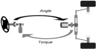
[image:3.595.60.269.634.738.2]The main feature of future steering systems is the missing direct mechanical link between steering wheel and steered wheels. With such a steer-by-wire steering system Fig. 3 the missing steering column’s function must be reproduced in both directions of action. In forward direction the angle set by the driver at the steering wheel is measured by a steering angle sensor and transferred with the suitable steering ratio to the wheels. In reverse direction the steering torque occurring at the wheels is picked up via a torque sensor and attenuated respectively, modified fed back to the driver as a counter torque on the steering wheel.
Fig. 3:
Principle illustration steer-by-wireFirst, steering wheel module and steering module are implemented with familiar components of mechanical and electrical steering systems, like: Steering wheel, gearbox, electrical motors, and rack. The operational principle is, however, in principle open for more futuristic designs like side stick operation on the driver’s side and single wheel steering on the wheel side. While in systems with mechanical connection in the case of electrical errors only the steering boost is concerned, corresponding measures must be taken with steer-by wire systems that in case of any electrical failure steering control is always guaranteed.
5. SYSTEM STRUCTURES OF SAFE ELECTRICAL
STEERING SYSTEMS
5.1. System Structure of Electrical Power Steering Functional Description
In an electrical power steering system the steering torque initiated by the driver Fig. 4 is measured by a steering wheel torque sensor and is fed into an electronic control unit. The latter then calculates along with the driving speed a reference torque for the steering motor, which, however, can optionally also depend on the steering angle and steering angle velocity. By means of the calculated reference torque the currents of the steering motor are actuated. Fig. 4 shows the pinion-type realization, where at the pinion the electrical torque is superimposed to the torque initiated by the driver. In further versions both torques can be superimposed either on the steering column or on the rack. In case of a failing electrical component of this steering system the non-boosted mechanical intervention by the driver is maintained.
Safety Features
© 2017, IRJET | Impact Factor value: 5.181 | ISO 9001:2008 Certified Journal | Page 2155
Fig. 4: System structure of Electric Power Steering
5.2. System Structure of the Purely Electrical Steer-By-Wire System
Functional Description
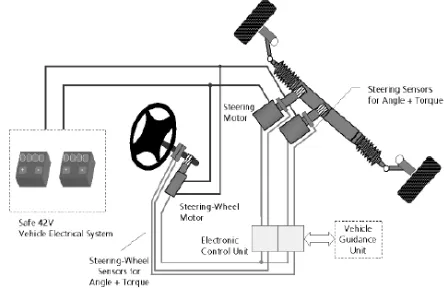
Fig. 5 shows the structure of a purely electrical steering system. The reduced safety by omitting steering column and hydraulic backup is compensated by higher demands on the safety structure of electrical and electronic components. Again, the system consists of components at the steering wheel, on the vehicle wheel level, and it comprises a control unit and a 42V vehicle electrical system. In this case this must be implemented as a safe 42V vehicle electrical system containing additional elements for the diagnosis of charge condition, as well as for the disconnection of batteries. Fig. 5 shows the structure of a purely electrical steering system. The reduced safety by omitting steering column and hydraulic backup is compensated by higher demands on the safety structure of electrical and electronic components. Again, the system consists of components at the steering wheel, on the vehicle wheel level, and it comprises a control unit and a 42V vehicle electrical system. In this case this must be implemented as a safe 42V vehicle electrical system containing additional elements for the diagnosis of charge condition, as well as for the disconnection of batteries.
Fig. 5: System structure of purely electrical steer-by-wire system
The steering wheel motor and sensors indicating steering wheel angle and steering wheel torque are arranged at the steering wheel. These components identify the driver’s desire and reproduce the return forces transferred to the steering wheel. For a safe acquisition of steering wheel position two redundant steering angle sensors are used. Power stage and power supply for the steering wheel motor are likewise redundant. In order to exert a return force on the steering wheel in case of a defective steering motor a torsion spring is available to generate the return torque. Optionally a second steering wheel motor can be used in order to redundantly generate the return torque. On the vehicle wheel level the system is equipped with a redundant set of electric motors and redundant sensors measuring angles and torques. The electronic control unit is designed fail-safe in terms of redundant power supply, signal processing and power actuation. Sensor values are identified periodically and redundantly, further processed via matched control algorithms and the calculated actuation signals are supplied to the two steering motors as well as the steering wheel motor. As to the link between the electronic control unit and the vehicle guidance unit as well as dividing the functions of these components to the decentralized units the explanations are in accordance with what has been described earlier referring to the steer-by-wire system with hydraulic backup.
Safety Features
Failure tolerance is required in these areas: sensors, electronics, actuators, vehicle electrical system and data transmission. This is accomplished by appropriate redundant structures. The fail-safe behavior against electric faults is to defective channel during signal detection or signal processing requires majority decisions. The needed redundancy is achieved either by hardware components or by including additional processing variables of the same kind. The defective channel is then switched-off consequently. In spite of electrical faults both steer ability and vehicle dynamic interventions are ensured on account of the redundant system structure.
6. ELECTRIC POWER ASSISTED STEERING
[image:4.595.54.276.584.729.2]© 2017, IRJET | Impact Factor value: 5.181 | ISO 9001:2008 Certified Journal | Page 2156 years ago. But for the first time in 1993, Honda introduced
[image:5.595.38.290.276.410.2]full time electric power steering in regular production car, Acura NSX. This is an exotic sports car, competing in the market with Ferrari and Porsche; later this, a small European market economy car, the Fiat Punto will have Delphi‘s electrically boosted E-STEER as standard equipment. Delphi is busily marketing their electric power steering system to the world’s automotive design engineers, and it is expected to show upon several domestic cars in just a few years. There are lots of advantages to using an electric motor to provide steering boost, and many automotive engineers believe we now are seeing the last generation of hydraulic power steering. With a large change just around corner, a look at how electric power steering works imperative.
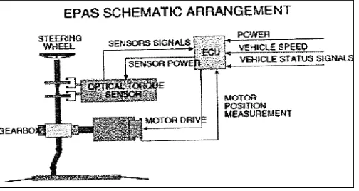
Fig. 6: Schematic arrangement of EPAS
7. COMPONENTS OF EPAS
1.Torque sensor: A torque sensor, torque transducer or torque meter is a device for measuring and recording the torque on a rotating system, such as an engine, crankshaft, gearbox, transmission, rotor,
a bicycle crank or cap torque tester. Static torque is relatively easy to measure. Dynamic torque, on the other hand, is not easy to measure, since it generally requires transfer of some effect (electric, hydraulic) from the shaft being measured to a static system.
2. Electronic control unit:Electronic Control Unit (ECU) is
any embedded system that controls one or more of the electrical system or subsystems in a transport vehicle. The electronic principle is simple, but it relies on to features developed just for this application. First is the very advanced algorithm in the computer program that calculates steering wheel position and torque, essentially giving the machine the ability to interpret the human driver‘s intensions. After that, the control unit simply chooses and appropriate output from a look-up table, similar to the way engine computers control ignition timing.
3. Motor Design: Achieving a smooth, progressive feel at the steering wheel requires a motor with low levels of ripples and cogging torque. Lucas variety, therefore, uses a three-phase inverter to control motor three-phase current, and hence
torque. An array of MOSFETS makeup the circuitry; pulse with modulation (PWM) regulates switching time sequence for the MOSFETS stages. Since the power-switching stage encompasses the most complex dynamics of the whole EPAS system, optimization requires computer simulation. Lucas uses the saber simulator program from US software house analogy Inc. to analyze alternative PWM strategies, and to model the complex patterns of secondary currents induced when the MOSFETS stages are switched. The aim is to ensure smooth control of the switching stages and also reduce the ripple currents fed into the battery harness. These currents have to be filter out to protect the electronics in the EPAS control unit. Bye minimizing the ripple current, they are able to use filter currents with lower ripple specifications and, therefore, lower cost.
4. Switches: An electrical switch is any device used to interrupt the flow of electrons in a circuit. Switches are essentially binary devices: they are either completely on ("closed") or completely off ("open"). There are many different types of switches.
Though it may seem strange to cover this elementary electrical topic at such a late stage in this book series, I do so because the chapters that follow explore an older realm of digital technology based on mechanical switch contacts rather than solid-state gate circuits, and a thorough understanding of switch types is necessary for the undertaking. Learning the function of switch-based circuits at the same time that you learn about solid-state logic gates makes both topics easier to grasp, and sets the stage for an enhanced learning experience in Boolean algebra, the mathematics behind digital logic circuits.
5. Steering System: The steering system comprises of a steering wheel turning a steering column. The steering column is connected to an intermediate shaft through a universal joint. The universal joint transmits torque to a lower shaft through another universal joint. A pinion at the end of the lower shaft mates with the rack and converts the column rotary motion into translator motion of the rack. For modeling purposes, the rack can be visualized as two similar sections on either side of the pinion.
8. SELECTION OF MATERIAL
The proper selection of material for the different part of a machine is the main objective in the fabrication of machine. For a design engineer it is must that he be familiar with the effect which the manufacturing process and heat treatment have on the properties of materials. The Choice of material for engineering purposes depends upon the following factors:
1. Availability of the materials.
2. Suitability of materials for the working condition in service. 3. The cost of materials.
© 2017, IRJET | Impact Factor value: 5.181 | ISO 9001:2008 Certified Journal | Page 2157 5. Mechanical properties of material.
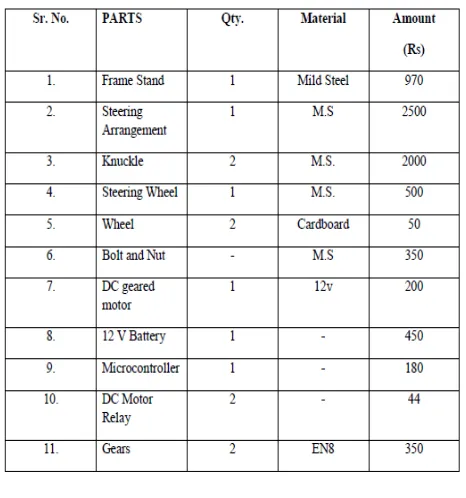
Table 1: Part list
9. SPECIFICATIONS OF COMPONENTS
1) D.C. Geared Motor
Speed = 10 rpm, Power = 18 watts, Voltage = 12 V DC
2) Battery
Voltage = 12 V, Current = 1.3 Ah, Type = Lead Acid
3) Microcontroller
Type = SST89E516RD2
4) DC Motor Relay
Voltage = 5 V DC, Output Voltage = 24 V , Output Current = 10 A
5) Steering System
Original Equipment Manufacturer (OEM) Vehicle – Maruti 800
6) Gears
Number of teeth = 24, Diameter = 30mm, Gear Ratio = 1:1 Module = 1.25 mm
Fig. 7: Final Assembly of Project
10. DESIGN OF MACHINES
Motor
Rpm of motor = 10 rpm, Power of motor = 18 watts, Motor output shaft diameter = 6 mm Shaft length = 20 mm Output torque of motor –
P = 2ΠNT/60 18 = 2xΠx10xT/60 T = 17.188 Nm T = 17188 Nmm
11. COST ESTIMATION
[image:6.595.313.546.286.535.2]Material Cost
Table 2:Cost Estimation
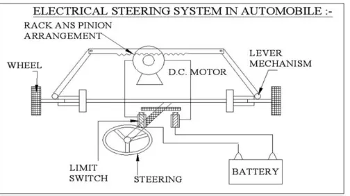
12. WORKING OF PROJECT
In our project acid 12 Volt batteries is used. The lead-acid batteries output is given to the limit switch. There are two Limit switches are used in this project. These switch outputs are connected to the steering D.C motor in Forward and reverse rotation of operation.
[image:6.595.36.289.621.743.2]© 2017, IRJET | Impact Factor value: 5.181 | ISO 9001:2008 Certified Journal | Page 2158 right side limit switches, so that the D.C motor rotate in
[image:7.595.37.289.134.275.2]reverse direction to move the wheel in right side
Fig 12: Basic Construction of Electrical Steering system in automobiles
13. CONCLUSION
These drawbacks are however only temporary barriers for the large scale introduced of these systems in today‘s cars and it can be unequivocally stated that EPAS is the future in power steering. The advantages far outweigh the disadvantages and as the system components get introduced at more economical prices, EPAS will become most efficient, safe and reliable power steering system.
Active Steering Systems are evolving in the direction of interaction with several vehicle features: agility, safety and comfort. From the implementation viewpoint, some of these improvements can be obtained providing a feedback to the driver through a torque overlay superimposed to the conventional assist torque. Using the instruments of system theory and frequency analysis it is possible to transform requirements, described in words, in specific modification requirements for peculiar target transfer functions. Exploiting knowledge of the various elementary transfer function (steer system, EPS-SW, road-vehicle interaction, vehicle dynamics and driver), it is possible to determine the a-priori behavior of the target transfer function and, by comparison with its desired behavior, modifications can be proposed to the existing EPS logics
13. THE FUTURE SCOPE
Steer-By-Wire:-
The aim of steer-by-wire technology is to completely do away with as many mechanical components (steering shaft, column, gear reduction mechanism, etc.) as possible. Completely replacing conventional steering system with steer-by-wire holds several advantages, such as:
1. The absence of steering column simplifies the car interior design.
2. The absence of steering shaft, column and gear reduction mechanism allows much better space utilization in the engine compartment.
3. The steering mechanism can be designed and installed as a modular unit.
4. Without mechanical connection between the steering wheel and the road wheel, it is less likely that the impact of a frontal crash will force the steering wheel to intrude into the driver's survival space.
5. Steering system characteristics can easily and infinitely be adjusted to optimize the steering response and feel.
REFERENCES
[1] Steve Fankem et. al. ” “Model-based Rack Force Estimation for Electric Power Steering”, The International Federation of Automatic Control, (2014) [2] Mohammad Kristamto et.al. “ Measuring geometric and kinematic properties to design steering axis to angle turn of the electric golf car.”, International Conference on Sustainable Energy Engineering and Application, (2015)
[3] Fan Chang-Sheng et. al. “Design of the Auto Electric Power Steering System Controller”, International Workshop on Information and Electronics Emgineering, (2011)
[4] M. K. Hassan et. al. “Optical design of Electric Power Assisted Steering (EPAS) using GA-PID method”, International Symposium on Robotics and Intelligent Sensors, (2012)
[5] Weidong Zhang et. al. “Design and Control Implementation of AC Electric Power Steering System Test Bench”, International Conference on Applied Physics and Industrial Engineering, (2011)
[6] Hao Chen et. al. “Study on Electric Power Steering System Based on ADAMS”, Advanced in Control Engineering and Information Science, (2011)
[7] Branneby, P.; Palmgren, B.; Isaksson, A.; Pettersson, T.; Franzen, S. (SAAB): “Improved Active and Passive Safety by Using Active Lateral Dynamic Control and an Unconventional Steering Unit“. 13th Int. Technical Conference on Experimental Safety Vehicles, Paris, 2000, pp. 224-230.
[8] Daimler-Chrysler: Forschung und Technologie: Steer-by-wire, Neuartige Assistenzsysteme,Mobiler Arbeitsplatz,Internetsite
http://www.daimlerchrysler.de/investor/annual98/ fue1_g.htm 3/99.
[9] Dr. Kirpal Singh, “Automobile Engineering”, Volume 1, 2013
[10] Giancarlo Genta et. al. “The Automotive Chassis”, Volume 1, 2009
© 2017, IRJET | Impact Factor value: 5.181 | ISO 9001:2008 Certified Journal | Page 2159
BIOGRAPHIES
Mr.Vishal Vijay Chahare
received his Master of Engineering [CAD/CAM] in 2015 from Babasaheb Naik College of Engineering Pusad, Maharashtra, India. Presently he is working as Asst Prof in Deogiri Institute of Engg & Mgmt Studies Aurangabad Maharashtra, India. His research interests are Automobile & I.C.engines.
Miss. Indira Ashokrao Mhaisne
received her Master of Engineering [HEAT POWER] in 2016 from JSPM Narhe Technical Campus, Pune,Maharashtra,India. Presently she is working as Asst Prof in Bhivarabai Sawant College of Engineering and Research & Polytechnic, Maharashtra, India Her research interests are Power engineering & Thermal engineering.