Design and Implementation of
Embedded-Human Machine Interface (HMI)
using PIC24FJ256DA210 Microcontroller
Gurpreet Singh
Electronics and Communication Engineering, Ludhiana College of Engineering and Technology,
Ludhiana (INDIA)
Surekha Rani
Electronics and Communication Engineering, Ludhiana College of Engineering and Technology,
Ludhiana (INDIA)
ABSTRACT
This paper focuses on integration of graphic and touch screen in Human Machine Interface using PIC24FJ256DA210 microcontroller which has integrated graphic controller. In this paper we have successfully implemented graphic and touch screen to control various kind of devices such as relay, speed and direction control of motor and input sensors which are key components for making HMI which is used for Industrial applications.
General Terms
PIC24FJ256DA210 MCU, Microchip Graphic Library, MPLAB X, MPLAB Complier, Graphic Display
Keywords
Embedded HMI, PIC24F 16-Bit Microcontroller Graphic Interface, Add Color Graphic LCD and Touch Screen in Industrial Applications.
1.
INTRODUCTION
This paper is targeted to integrate colour graphic LCD and touch screen for industrial applications such as Human Machine Interface. The main objective is to replace traditional mono-chrome LCDs and mechanical switches, with colour graphical LCD and touch screens. Graphical display systems like mobile phone, mp3 player, IPODs, glucose meter etc. are having colour graphical LCD. The hardware and software designing of these kinds of system is very important for
proper operation, size, resolution and clarity of Graphic LCD.
In this paper, we are using PIC24FJ256DA210 MCU with integrated graphical controller. The PIC24FJ256DA210 is a unique product because it is the first 16-bit MCU with integrated graphics and also capacitive touch sensing. It is specifically targeted at cost sensitive graphical interface applications. On the graphics front, the PIC24FJ256DA210 integrates the 96K byte frame buffer support. It adds three graphics accelerator and DMA engines to accelerate graphics objects[1].
It adds a 256 x 16-bit per entry colour lookup table to support up to 256 colours of 16-bit per pixel depth. On the display interface side, the family provide direct interface support to monochrome, C-STN, TFT and OLED. With this direct interface, designers can now eliminate the need of external LCD controller to support graphics displays and save overall system BOM cost. Lastly, it supports up to 480x272 (WQVGA) resolution at 60Hz @ 16bpp, or up to 640x480 (VGA) resolutions @ 60Hz @ 8bpp[1].
We have studied and implemented the interfacing techniques and other parameters of different colour graphical LCD with
Microchip’s PIC24FJ256DA210 16-Bit MCU with Integrated Graphical Controller suitable to small resolution LCD for Handheld and Industrial applications. The PIC24FJ256DA210 family allows the CPU to fetch data directly from an external memorydevice using the EPMP module which can also use for interfacing frame buffer. The graphic controller also implemented loss-less Huffman coding inside the hardware [2].
In graphic front, a screen is made up of discrete elements, known as pixels. Every pixel can show one point of colour and each pixel is composed of three points: red, green and blue. The colours are arranged next to each other on a colour screen. The number of such pixels in horizontal and vertical directions is called screen resolution [3]. The figure 1 shows an example of truly 3.2 inches LCD 320 x 240 part number TFT2N0369-E[4] Graphical LCD QVGA (Quarter Video Graphics Array) is measured diagonally which is used to implement in this project. An example is also depicted as figure more the pixels in lesser area means more resolution and better quality of images.
Figure 1
Different types of LCD means different dimensions and resolutions are also available [5]. The display controller continuously reads data from the display buffer, and then gives output to display with the display clock, vertical and horizontal synchronization signals, and enable signal configured on the specifications of the display. Timing of the synchronization signals, polarity of the signals, and required frame rate of the display are determined from the display specifications and translated to values to be programmed into the registers of the display controller [2]. Microchip’s ICD3 programmer/debugger is used for development purposes.
Red, 6 Signals for Green and 5 for blue.As Green color is less predicted by human eye ‘1’ extra pin assign for that [5].
2.
GRAPHICS TECHNOLOGIES
The PIC24F “DA” family makes it easy and cost-effective to add advanced graphics to your application by eliminating the need for external frame buffers or display controllers.
• Dedicated graphics clock for a continuous, clean display. • On-chip display controller provides direct interface to TFT, STN and OLED displays
• Easy to use Graphics Processing Units for hardware acceleration
- Move and copy rectangles with smooth, fast memory transfers
- Decompress images without CPU intervention - Render text without CPU intervention [1, 2]
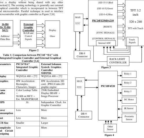
[image:2.595.61.560.286.764.2]The main advantage of hardware acceleration in this family it is able to process and render graphics without using any MCU MIPS. The dedicated graphics engine is able to continuously drive a display without being shared with any other function[1]. The existing technology is generally use external graphical controller which is incorporated in between TFT and microcontroller. Parallel technique in used to interface microcontroller with graphic controller as Figure 2 [6].
Figure 2
Table 1: Comparison between PIC24F “DA” with Integrated Graphic Controller and External Graphical
Controller [1,6] Parameters PIC24“DA”
Integrated Graphic Controller
External Solomon Systech Graphics Controller SSD1926
Display WQVGA 480 × 272 WQVGA 480 × 272
Graphics HW Acceleration: Rectangles, Characters, Images
HW Acceleration, SD card, JPEG Coder,2D graphic engine
Frame Buffer
Color Lookup Table +
96 KB on MCU + Ext SRAM/PSRAM
256K Embedded Display SRAM + Image Processor
MIPS 16 Independent Clock for Graphic Controller
Power Consumption
Less More
Cost Less More
PCB Size Smaller Larger
Complexity and Circuit Designing
Less More
There are different kinds of external graphical controllers are available. The above comparison is made between PIC24F “DA” and Solomon Systech SSD1926. The SSD1926 has JPEG engine and SD card interface. So, if application doesn’t require JPEG engine, 2D and SD card then PIC24F “DA” much is suitable for driving 480x272 (WQVGA) resolution at 60Hz @ 16bpp with external SRAM and less power consumption at lower Cost[2].
3.
HARDWARE IMPLEMENTATION
This project is divided in to two parts: 1) Graphic and Touch Screen – HMI Board 2) Input-Output Devices – 8-bit Controller Board
In this we have used PIC24FJ256DA210 with external SRAM for Interfacing Truly 3.2 TFT – TFT2N0369-E [4, 5] and the second part of the project is Input-Output devices which connected with PIC18F4520 8-Bit microcontroller[7]for the ease of connections and provide separability between HMI and I/O devices. Interfacing of both modules is done by serial communication of USART with baud rate of 19200 Bps.
Figure 3
Figure 4
[GD 15-11]Red
[GD 10-5] Green
[GD 0-4] Blue
PIC24FJ256DA210
[RESET]
[SYNC SIGNALS]
[CONTROL SIGNALS]
TFT 3.2
inch
320 x 240
TFT with Touch
BACK LIGHT CONTROLLER
MAX
3232
DB-9 Connector
Internal ADC
Touch Signals
DB-9 Connector
MAX
3232
PIC18F4520
Relay 1
Relay 3 Relay 2
DC Motor
IR Sensor
Other Sensor
Proximity Sensor
16-Bit Or 32-Bit
MCU
Address/ Data Bus
Display
Glass
External Graphic Controller
Figure 3 and Figure 4 show circuit overview of both modules and both have independent MAX3232 and they are connected in cross connection fashion for serial communication.
4.
SOFTWARE IMPLEMENTATION
Since, there are two microcontrollers are used, so two different programs are developed and both are interacted with each other by Serial Communication.
4.1
Software Implementation for Graphic
and Touch Screen – HMI
The software is implemented on Microchip’s well known Platform MPLAB® X IDE, MPLAB® C30 Compiler and Microchip Graphics Library.
MPLAB® X IDE is a software program that runs on a PC (Windows®, Mac OS®, Linux®) to develop applications for Microchip microcontrollers and digital signal controllers. It is called an Integrated Development Environment (IDE), because it provides a single integrated “environment” to develop code for embedded microcontrollers [8].
The MPLAB® C Compiler for PIC24 MCUs and dsPIC DSCs (also known as MPLAB C30) is a full-featured ANSI compliant C compiler for the Microchip 16-bit devices: PIC24, dsPIC30F and dsPIC33F. MPLAB C is a 32-bit Windows® console application as well as a fully integrated component of Microchip’s MPLAB Integrated Development Environment (IDE), allowing source level debugging with the MPLAB REAL ICE™ Emulator, MPLAB ICD 2 In-Circuit Debugger and MPLAB SIM Simulator [9].
For drawing widgets and use of Touch screen such as Button, Edit Box, Text, Meter and Inserting Image etc. is done the Microchip Graphic Library[10]. Authors have used pre-made objects in the library. The Microchip Graphics Library is highly modular and is optimized for Microchip’s 16-bit microcontrollers. Additionally, the library is free for Microchip customers, easy to use, and has an open documented interface for new driver support, which requires creation of only one C file.
The Microchip Graphics Library Software Version 3.01 supports the following features [10]:
• Configurable graphic resolution • Up to 16-bit or 65K colors
• 2D objects such as line, circle, text, rectangle, polygon, bar • 3D objects such as buttons, meter, dial, list box, edit box, check box, radio buttons, window, group box, slider. • Image, animation
• Variety of user input device such as touch screen, keypad etc…
• Multiple fonts • Unicode fonts
• PIC24 support, PIC32 support™ sensing • Image, animation
4.2
Graphic LCD – Output Screens
Below figures show outputs on Graphic LCD screen after loading hex file in it. The figure 5 shows welcome screen when operator clicks on “Press Here” Button. The screen goes to figure 6 which is “Relay Interfacing” Screen. When “Relay
1” switch is pressed, Activated is written in EditBox “Status 1” and so on for other relay interfaces also. After pressing Next button screen, screen goes to figure 7. Here operator can test speed with “increase” and “decrease” buttons and direction with “forward” and “reverse” buttons. The next screen in figure 8 is responsible receiving input signals from sensor to graphic display.
Figure 5
Figure 6
Figure 7
various kind of style schemes can used for creating widgets. But, in this we have only used default style scheme [10].
4.3
Software Implementation for
Input-Output Devices 8-bit Controller Board
[image:4.595.316.543.435.664.2]This part of software is implemented on Microchip’s MPLAB® X IDE, MPLAB® C18 Compiler.The MPLAB® C Compiler for PIC18 MCUs (also known as MPLAB C18) is a full-featured ANSI compliant C compiler for the PIC18 family of PICmicro® 8-bit MCUs. MPLAB C is a 32-bit Windows® console application as well as a fully integrated component of Microchip’s MPLAB Integrated Development Environment (IDE), allowing source level debugging with MPLAB’s software and hardware debug engines.
Figure 8
Projects, compiler switches and linker customizations can be controlled completely within MPLAB IDE to provide a full graphical front end for this powerful compiler. Text errors in source code and breakpoints instantly switch to corresponding lines in the proper file, and watch windows show data structures with defined data types, including floating point, arrays and structures [11].
The PIC18F4520 microcontroller works on serial interrupt. Whatever the character coming from HMI Board, the PIC18F4520 microcontroller receives it and do appropriate actions as below:
if (RCREG=='1') {
RELAY1^=1; DelayMS(20); }
if(RCREG=='2') {
RELAY2^=1; DelayMS(20); }
if(RCREG=='3') {
RELAY3^=1; DelayMS(20); }
if(RCREG=='4') {
MOTOR1=1; DelayMS(10); MOTOR2=0; DelayMS(10); }
if (RCREG=='5') {
MOTOR1=1; DelayMS(10); MOTOR2=0; DelayMS(10); }
if(RCREG=='6') {
MOTOR1=0; DelayMS(10); MOTOR2=1; DelayMS(10); }
5.
COMMUNICATION BETWEEN TWO
MODULES
Both the boards are communicating with USART of PIC24F256DA210 and PIC18F4520 MCUs. They work as full duplex mode. The USARTs on both ends work on Interrupts. The HMI part is send one character to I/O controller board. The I/O controller board receives character and performs appropriate operation according to program written in I/O controller board.
6.
RESULT ACHIEVED
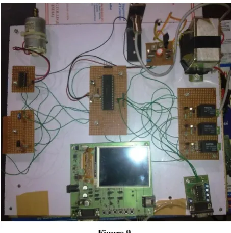
In this Project, the screens are successfully created with image, button, text with different fonts, Editbox and Lines. The touch screen is also working fine here. The Back, Next buttons are used to shift the screens. The controlling of DC motor and reading shown on meter on Graphical LCD, Switching of relays is successfully done with Graphical LCD using Touch Screen. Input sensors are shown status on EditBox on specified screen.
Figure 9
6.
CONCLUSION
because declining the price of colour graphic LCD on last few year either it is TFT or LCD is low. Graphic add cool features product, touch screen make it more effective, enrich user experience and add interactive look in product.
The development cycles of these products are much lengthier, complex, complicated as compared to monochrome LCD. Also you need experienced staff for development of this kind of product in hardware and software manner as well.
7.
ACKNOWLEDGEMENT
With deep sense of gratitude we express our sincere thanks to our esteemed and worthy Mr. Rajeev Sobti , Associate Dean, School of Computer Sciences, Lovely Professional University, Phagwara, India for his valuable guidance in carrying out this work. We also thanks to Mrs. Archana Aggarwal from Institue of Technology & Management, Bhilwara, Rajasthan , India for presenting this paper. At Last, we thanks to management of Imbuent Technologies Pvt. Ltd. for allowing us to use their resources for project work.
8.
REFERENCES
[1] Datasheet, "PIC24FJ256DA210 Family Datasheet" DS39969B, Microchip Technology Inc., 2009.
[2] Section 43,"Graphics Controller Module (GFX)", DS39731A, Microchip Technology Inc., 2009.
[3] AN1368,"Developing Embedded Graphics Applications using PIC Microcontrollers with Integrated Graphics controller", DS01368A, Microchip Technology Inc., 2011
.
[4] Datasheet,"TFT2N0369-E Version: 1.0", January 15, 2009.
[5] Gurpreet Singh and Amanpreet Singh "Design and Hardware Implementation of Graphical Display Systems using PIC24FJ256DA210 Microcontroller with Integrated Graphic Controller", IJECT Vol. 3, Issue 1, Jan. - March2012
[6] Datasheet,"SSD1926 Semiconductor technical data", Rev 1.2, Solomon Systech Limited, Dec 2007.
[7] Datasheet, "PIC18F2420/2520/4420/4520 Datasheet", DS39631E, Microchip Technology Inc., 2008.
[8] User’s Guide "MPLAB® X IDE User’s Guide", DS52027B, Microchip Technology Inc., 2011-2012.
[9] User’s Guide "MPLAB® C Compiler for PIC24 MCUs and dsPIC® DSCs", DS51284K Microchip Technology Inc., 2002-2011.
[10]Manual, "Microchip Graphics Library V3.11" Microchip Technology Inc., 2011.
[11]User’s Guide "MPLAB C18 C Complier user’s guide", DS51288F, Microchip Technology Inc., 2005.
9.
AUTHORS PROFILE
Mr. Gurpreet Singh is pursuing M-Tech (Part-Time) from Ludhiana College of Engineering and Technology, katani kalan, Ludhiana. He is working as project manager in Imbuent Technologies Pvt. Ltd. He has attended and organized many embedded workshops and conferences. His areas of interests are embedded hardware designing, software programming and digital image processing. He has submitted this project as final year project in his M. Tech.