Improved Arbitrary Size Benes Network
Gaurav Kumar
Department of Computer ScienceGuru Nanak Dev University, Amritsar
Sandeep Sharma,
PhD Assistant Professor Department of Computer ScienceGuru Nanak Dev University, Amritsar
ABSTRACT
Multistage interconnection networks (MINs) are used to connect N inputs to N outputs. They are mainly used to connect processor to processor and for processor to memory in distributed and shared memory environment. The MINs are broadly divided into three categories Blocking Non Blocking and Rearrangeable networks. A new improved Arbitrary size Benes network has been proposed in this to improve the permutation capabilities and to reduce the cost of existing Arbitrary Size Benes Network.
General Terms
Benes network, Arbitrary size Benes network, Permutation capability, Path, Path length, Rearrangeable non blocking network.
Keywords
Improved Arbitrary size Benes network, Arbitrary size Benes network path, Improved Arbitrary size Benes network path, Arbitrary size Benes network path length, Improved Arbitrary size Benes network path length.
1.
INTRODUCTION
A network is said to be Rearrangeable Non Blocking if it can realize all possible permutation between all possible input and output pairs.[3,1,10,12] Benes networks are the example of such kind of networks. A Benes network is a special instance of CLOS network. In Benes network a set of paths exist between inputs and outputs. So there are no of ways and no of possibilities exists in Benes network to fulfill a output request. If a Benes network consists of 2𝑟 inputs and 2𝑟 outputs then It contains 2r-1 level of switches and each level contain
2
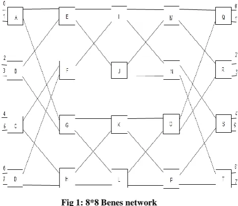
𝑟−1 no of switches.For example A Benes network with r=3 is shown in figure 1. The Benes network shown in figure 1 having r=3 so
2
3 = 8 inputs are connected to2
3 =8 outputs. The no of stages in the network are 2*3-1 =5 and there are2
3−1 = 4 switches in each stage. The first stage of switches is connected to second stage of switches similar to the fourth and fifth switching stage connections and the middle two stages are similar in connections. The inputs and outputs are connected sequentially to the first and last stage of switches for example the 0 and 1 inputs are directly connected to A switch and 0’ and 1’ output is directly connected to Q switch. [5,1,8,9]Fig 1: 8*8 Benes network
1.1
Arbitrary size Benes network
According to Benes topology the size of the Benes network is always the power of 2. This is a kind of restriction which led’s to the wastage of resources. For example in some cases the requirement of the network is not in even number but due to size restriction the designed network is in power of 2 so the remaining nodes always remain idle. The Arbitrary size Benes network provide us the facility to design any size of network it can be of even size or odd size.[1,6,11,13]
1.1.1
Construction strategy
To construct a Arbitrary size Benes network of size N a recursive technique is used. The N size Arbitrary size Benes network is constructed from a𝑁
2 size of Arbitrary size Benes
network. If N is even the construction is similar to Benes network the N no of input are connected to 𝑁
2 no of switches
and each switch is connected to the two Arbitrary size of Benes network of size 𝑁
2 as shown in figure 1 a 8*8 even size
Benes network . If N is of odd size the first N-1 input and outputs are connected similarly to even size network as shown in figure 1the last input and output are connected directly to lower 𝑁
2 Arbitrary size Benes network. A Arbitrary size Benes
[image:1.595.318.559.205.413.2]Fig 2: Odd size Arbitrary size Benes network
1.2 Improved Arbitrary size Benes network
For even size network the procedure remain the same as shown above the standard Benes network procedure. For a odd size Arbitrary size Benes network the procedure is different from standard procedure. Divide the network in to two half’s such that the upper network contains 𝑁−1
2 inputs
and outputs and similarly the lower network contains 𝑁−1
2
inputs and outputs and connect these inputs to 𝑁−1
4
switches
such that 𝑁−1
2 inputs of upper network is connected to 𝑁−1
4
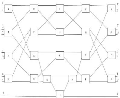
[image:2.595.367.489.335.423.2]of switches similarly lower inputs. The next connections are according to Benes networks the middle input which makes network a odd network is connected to both upper and lower networks. For example consider a 9*9 Arbitrary size Benes network the connection according to our strategy is shown in figure 3.
Fig 3: Improved Arbitrary size Benes network
In above figure the upper network contain 0 to 3 inputs and lower network contain 5 to 8 inputs the upper networks inputs are connected to A and B switches while lower network input are connected to C and D switches while the 4 input is connected to both networks by U switch similarly outputs are connected to Q and R switches in upper network and to S,T in lower network.
2. PERMUTATION CAPABILITY OF
IMPROVED ARBITRARY SIZE BENES
NETWORK
2.1 Permutation capability
Permutation capability means how many input requests occurring simultaneously at the input are able to pass through a given network and how many of them will successfully mature i.e. will reach their destination. [2]2.2 Path
The way used by the signal to reach from source to destination.2.3 Path length
Length of the path followed by the signal.2.4 Assumptions
2.4.1 Path
In path if straight state of switch X is used by the signal then X is used in path if exchange state is used by signal then X’ is used in path for example consider switch A as shown in figure 4.
Fig 4: Switch A
In first that is in case of exchange we will use A’ in path. In second means in case of straight we will use A’ in path.[7]
2.4.2 Path length
The path length is considered to be half if signal enters as a input and comes out as a output from the switch.
One when signal goes from switch to switch.
[image:2.595.309.549.484.754.2] Negligible inside the switch .
Table 1. Results of 0 to 0’ permutations.
Sno Input Output Path Length
1 0 0’ 0AEIMQ0’ 5
2 1 1’ 1AG’LO’Q1’ 5
3 2 2’ 2BEUKO’R’2’ 6
4 3 3’ 3BG’JMR’3’ 5
5 4 4’ 4U4’ 1
6 5 5’ 5CFINS5’ 5
7 6 6’ 6CH’LPS6’ 5
8 7 7’ 7DFKP’T’7’ 5
[image:2.595.59.277.484.667.2]Table 2. Results of 0 to 8’ permutations
Sno Input Output Path Length
1 0 8’ 0A’G’L’PT8’ 5
2 1 7’ 1A’E’I’N’T7’ 5
3 2 6’ 2B’G’J’N’S’6’ 5
4 3 5’ 3B’EUK’PS’5’ 6
5 4 4’ 4U4 1
6 5 3’ 5CFI’MR’3’ 5
7 6 2’ 6CH’L’OR’2’ 5
8 7 1’ 7D’H’J’M’Q’1’ 5
9 8 0’ 8D’FK’OQ’ 0’ 5
Table 3. results of 8 to 0’ permutations
Sno Input Output Path Length
1 8 0’ 8DHL’O’Q’0’ 5
2 7 1’ 7DF’I’MQ’1’ 5
3 6 2’ 6CHJ’MR2’ 5
4 5 3’ 5CF’K’O’R3’ 5
5 4 4’ 4U4 1
6 3 5’ 3BG’P’S’5’ 5
7 2 6’ 2BE’I’NS’6’ 5
8 1 7’ IAGJ’NT7’ 5
9 0 8’ 0AE’UK’P’ T8’ 6
3. COMPARISON OF ARBITRARY AND
IMPROVED ARBITRARY SIZE BENES
NETWORK.
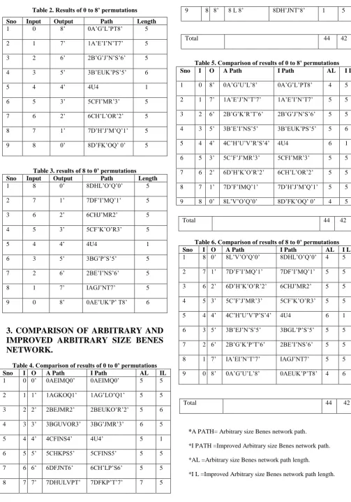
Table 4. Comparison of results of 0 to 0’ permutations
Sno I O A Path I Path AL IL
1 0 0’ 0AEIMQ0’ 0AEIMQ0’ 5 5
2 1 1’ 1AGKOQ1’ 1AG’LO’Q1’ 5 5
3 2 2’ 2BEJMR2’ 2BEUKO’R’2’ 5 6
4 3 3’ 3BGUVOR3’ 3BG’JMR’3’ 6 5
5 4 4’ 4CFINS4’ 4U4’ 5 1
6 5 5’ 5CHKPS5’ 5CFINS5’ 5 5
7 6 6’ 6DFJNT6’ 6CH’LP’S6’ 5 5
8 7 7’ 7DHULVPT’ 7DFKP’T’7’ 7 5
9 8 8’ 8 L 8’ 8DH’JNT’8’ 1 5
Total 44 42
Table 5. Comparison of results of 0 to 8’ permutations
Total 44 42
Table 6. Comparison of results of 8 to 0’ permutations
Sno I O A Path I Path AL I L
1 8 0’ 8L’V’O’Q’0’ 8DHL’O’Q’0’ 4 5
2 7 1’ 7D’F’I’MQ’1’ 7DF’I’MQ’1’ 5 5
3 6 2’ 6D’H’K’O’R’2’ 6CHJ’MR2’ 5 5
4 5 3’ 5C’F’J’MR’3’ 5CF’K’O’R3’ 5 5
5 4 4’ 4C’H’U’V’P’S’4’ 4U4 6 1
6 3 5’ 3B’EJ’N’S’5’ 3BGL’P’S’5’ 5 5
7 2 6’ 2B’G’K’P’T’6’ 2BE’I’NS’6’ 5 5
8 1 7’ IA’EI’N’T’7’ IAGJ’NT7’ 5 5
9 0 8’ 0A’G’U’L’8’ 0AEUK’P’T8’ 4 6
Total 44 42
*A PATH= Arbitrary size Benes network path.
*I PATH =Improved Arbitrary size Benes network path.
*AL =Arbitrary size Benes network path length.
*I L =Improved Arbitrary size Benes network path length.
Sno I O A Path I Path AL I L
1 0 8’ 0A’G’U’L’8’ 0A’G’L’PT8’ 4 5
2 1 7’ 1A’E’J’N’T’7’ 1A’E’I’N’T7’ 5 5
3 2 6’ 2B’G’K’R’T’6’ 2B’G’J’N’S’6’ 5 5
4 3 5’ 3B’E’I’NS’5’ 3B’EUK’PS’5’ 5 6
5 4 4’ 4C’H’U’V’R’S’4’ 4U4 6 1
6 5 3’ 5C’F’J’MR’3’ 5CFI’MR’3’ 5 5
7 6 2’ 6D’H’K’O’R’2’ 6CH’L’OR’2’ 5 5
8 7 1’ 7D’F’IMQ’1’ 7D’H’J’M’Q’1’ 5 5
4. COST COMPARISON
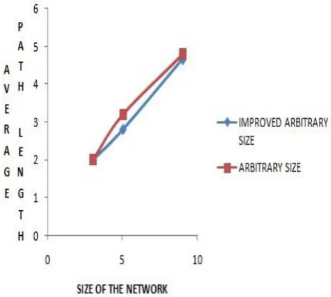
To compare the cost we have taken three different size Arbitrary size and Improved Arbitrary size Benes network and calculate their path lengths, average path lengths and no of switches used. The results are shown in the form of a tables and graphs below.
Table 7. Arbitrary size Benes Network
Sno Size Path Length
Average Path Length
Switches Used 1 3 6 2 3
2 5 16 3.2 8
[image:4.595.320.553.73.282.2] [image:4.595.56.287.162.602.2]3 9 44 4.8 22
Table 8. Improved Arbitrary size Benes network
Sno Size Path Length
Average Path Length
Switches Used 1 3 6 2 3
2 5 14 2.8 7
3 9 42 4.6 21
Fig 5: Comparison of path length of Arbitrary and Improved Arbitrary size Benes networks.
Fig 6: Comparison of average path length of Arbitrary and Improved Arbitrary size Benes networks.
So it clear from above graphs that the Improved Arbitrary size Benes network uses less switches to achieve the target and also provide better path length compared to the Arbitrary size Benes network. so Improved Arbitrary size Benes network is efficient and cost effective compared to the Arbitrary size Benes network.
5. CONCLUSION
With the help of Arbitrary size Benes we are able to design a Benes network of any size. A New Improved Arbitrary size Benes network has been proposed and analyzed. Three sizes (3, 5, 9) of both networks has been compared and analyzed. From calculations of number of switches and path length of both networks it has been concluded that Improved Arbitrary size Benes network uses less switches and having shorter path length compared to the Arbitrary size Benes network. So Improved Arbitrary size Benes network is more efficient and cost effective as compared to Arbitrary size Benes network.
6. REFERENCES
[1] Chihming Chang, Rami Melhem, “Arbitrary Size Benes Networks”, Journal: Parallel Processing Letters - PPL , vol. 7, no. 3, pp. 279-284, 1997.
[2] Er.Sandeep Kaur, Er.Anantdeep and Er.Deepak Aggarwal, “Effects of crosstalk on permutation of Optical multistage Interconnection networks”, Journal of computing, volume 2, Issue 4, Aprail 2010, ISSN 2151-9617.
[3] T.Y. Feng., “A survey of interconnection networks”, IEEE Computer, 14 (12):12-27, 1981.
[4] T. Leighton, “Introduction to parallel algorithms and architetectures Arrays, Trees, Hyper cubes”, Morgan Kaufmann Publishers, MIT, 1992.
[6] D. Opferman and N. Tsao Wu. “On a class of rearrangeable switching networks, part i: Control algorithm.”, Bell System Technical Journal, 50(5):1576-1600, 1971.
[7] Chunming Qiao, “A Two-Level Process for Diagnosing Crosstalk in Photonic Dilated Benes Networks”, Journal of Parallel and Distributed computing 41,53-66 (1997).
[8] Jayadev Misra
,
“
Generating-Functions of Interconnection Networks”, The University of Texas at Austin. July 17, 2000.[9] D. Nassimi and S. Sahni, “Parallel algorithms to set up the Benes permutation network,” IEEE Trans. Computers, vol. 31, no. 2, pp.148- 154, Feb. 1982. [10] Rinkle Rani Aggarwal, Dr. Lakhwinder Kaur Dr.
Himanshu Aggarwal, “Multistage Interconnection
Networks: A Transition from Electronic to Optical”, Journal of Emarging technologies in web intelligence,Vol. 2, no 2 May 2010.
[11] Chuan-Lin Wu, Tse-Yun Feng, “The Reverse-Exchange Interconnection Network”, IEEE Transactions on Computers, vol. c-29, no. 9, pp. 801-811,September 1980.
[12] Chi Hsin-Chou, Wu Wen-Jen, “Routing Tree Construction for Interconnection Networks with Irregular Topologies”, Proceeding of the Eleventh Euromicro Conference on Parallel, Distributed and Network-Based Processing (Euro-PDP),2003.