Enhanced performance of micro grid in islanded mode with
multi level inverter
Yatam Venkata Siva1,S.Rajshekar2
1M.Tech(Research scholar In Power Electronics),2assistant professor
in Department of Electrical and Electronic Engineering
Akula Sriramulu College Of Engineering & Technology,Tadepalligudem,Andhra Pradesh,India
Email:[email protected],[email protected]
Abstract
Micro grids frameworks are little scale power supply arranges that have neighborhood power era. Micro grids network got to be one of the key spot in examination on dispersed vitality frameworks. Micro grids are fit for both creating their own electric force with little scale conveyed era (miniaturized scale sources) and receiving/sending out energy to the fundamental utility lattice. In this undertaking a control system for inverter based MG which can guarantee soundness and appropriate force sharing among the inverters, in islanded mode, is proposed. A MG can be worked in two modes, matrix associated and islanded mode. Every mode has its own control methodology. Small scale lattices (MG), for the most part inverter based, are increasing more significance as they can oblige different sorts of DGs viably and for their unrivaled force quality. The general control logic inside of a miniaturized scale matrix is that sources must depend just on nearby data, yet must participate with different sources. To perform that objective, the proposed controller uses hang attributes
for dynamic force/recurrence and responsive
force/voltage. The proposed control procedure depends on the utilization of a stage bolted circle to quantify the miniaturized scale framework recurrence at the inverter terminals, and to encourage regulation of the inverter stage in respect to the Micro grids network. This control system permits miniaturized scale lattices to flawlessly transition between matrix associated and self-sufficient operation, and the other way around. The controller has been actualized in a real Micro grids network that joined different sources. The principle goal of the proposed controller is to infuse a clean sinusoidal current to the lattice, even in the vicinity of nonlinear/unbalance loads and/or network voltage twists. The tedious control strategy is embraced in light of the fact that it can manage an extensive number of sounds at the same time by utilizing MAT Lab/Simulink.
Keywords: Micro grid, islanded operation 1. Introduction
At the present time, Micro grids framework can be viewed as a controlled cell of a power framework. Illustration gratia, the cell may well be controlled as a solitary dispatch capable burden, which can respond in little time to give the requests of the transmission framework. On the client side miniaturized scale frameworks can be developed to address interesting issues. They help the neighborhood dependability, decrease feeder misfortune, bolster nearby voltages, convey prevalent adequacy through castoff waste warmth, voltage list rectification and giving uninterruptible influence supply works. Nowadays conveyed era is bringing more acknowledgment in a de-controlled environment. Joining of circulated era and absorption of controllers has led to customary force system to work as a dynamic force systems. Under this interruption the force system parts into part generators and burdens. The heap interest can be tallied with the supply force of an island. If there should be an occurrence of business and mechanical touchy burdens the need of prevalent force quality and unwavering quality is awesome. A Micro grids network can be a DC framework, an AC framework or even a high recurrence AC lattice framework. A Micro network framework is sorted out as an island.
The issue of disposing of harmonics in disposing inverters has been the center of examination for a long time. The present pattern of tweak control for multilevel inverters is to yield top notch power with
high productivity. Therefore, well known
high exchanging recurrence. The particular consonant disposal strategy has developed as a promising tweak control technique for multilevel inverters. The real trouble for the particular consonant end technique is to unravel the mathematical statements describing music; then again, the arrangements are not accessible for the entire balance file extent, and it doesn't dispense with any number of indicated sounds to fulfill the application prerequisites. The proposed symphonious disposal technique is utilized to dispense with any number of sounds and can be connected to DCMLI application necessities.
2. Power Network In Islanded Mode
Fig. 1: Converter based Power Network in islanded mode
The Figure 1 construes the plan of a fundamental miniaturized scale matrix. The framework involves a gatherer transport, a converter, a transport capacitor C and a heap. The heap is signified as a parallel mix of resistance R and inductance L and the heap is ventured to be in an imbalanced condition. With every one of these suspicions, a key recurrence model of the converter is legitimized, where the converter is demonstrated as a normal current source.
2. Mg In Grid Connected Mode
There are different entrenched control system to control strategies to control the inverters in a MG when it is working in Grid associated mode [2,3]. Much of the time, both of consistent current control or PQ control is utilized. These two strategies are quickly clarified underneath.
2.1 Constant Current Control
In this control method [2], inverters are forced to inject constant current output. The block diagram of this control shown in the fig.2. And its controller is shown in fig.3.
Fig. 2: Block diagram of Constant Current Control
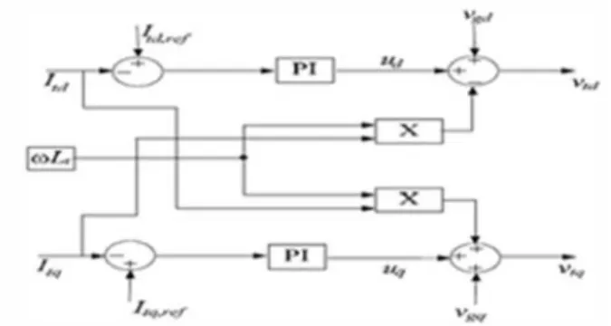
Fig. 3: Block diagram of Controller
The consistent current control measures the heap voltage Vgabc and the inverter current Igabc and exchanges them to dq outline. The converter amounts Id and Iq are then contrasted and reference DC
amounts Itd,ref(active force set point) and
Itq,ref(reactive force set point) to acquire mistake signals. The blunder signs are then connected to corresponding Integral (PI) controllers to adjust the mistakes and characterized the reference voltage signals Vtd and Vtq. These reference voltages are againe changed to three stage amounts and are given to the beat generator to produce beats for the inverter. By and large, this procedure compels the inverter to infuse the characterized streams and in the meantime it controls the voltage at the association point as measured from the network side.
3. PQ Control Method
The piece outline of PQ [3] control is appeared in fig.4. The control structure of this sort is calm like the consistent current control. The main distinction b tween the two controls is the directed parameters and they achieve the same conclusion, which is yield force control, in this control sort, the managed parameters control, in this control type, the regulated parameters are the active and reactive powers instead of the current.
Fig. 4: Block diagram of PQ Control
order to obtain Id,ref and Iq,ref. the rest of the process is similar to the constant current control technique shown earlier in fig.2 and .3.
4. Review Of Various Droop Control Techniques 4.1 Conventional Droop Method
The basic equations that governs tranfer of power in conventional power system are given by
(1)
(2)
From the equations, it is clear that real power is dependent on the phase angle delta or frequencey and the reactive power is based on the voltage profile of the system.these relations holds good in inductance dominated networks. Now, many wireless control strategies[4-7] for inverters in islanded operation use the various droop methods which are derived from Eq.(1) and Eq.(2)
(3)
(4)
Where, f and V are the instantaneous frequency and voltage of the system and f0 and V0 are nominal frequency and voltages respectively, and mp, mQ are the droop coefficients of the droop equations(3) and (4) respectively. The block diagram for the droop control is shown in fig.5.
Fig. 5: Block diagram of conventional droop method
As shown in the fig. 5, frequency reference is generated by real power Vs frequency droop and the reactive power Vs voltage droop generates the voltage magnitude reference. Now the voltage reference to the pulse generator is derived by using the following equations.
(5)
(6)
(7)
(8)
The required phase angle wt, can obtained by integrating the frequency w.
4.2 Opposite droop method
Incase of MGs where the network is resistive in natured, the basic equations that govern the power flows are given by the following equations.
(9)
(10)
(11)
(12)
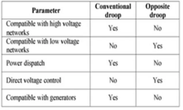
The block diagram for the opposite droop control method is shown in the fig.6. As shown in the fig.6, real power Vs frequency droop is used to get the reference of voltage magnitude. The comparison between the above two mentioned droop methods is shown in the following table.1.
Fig. 6: B ock diagram of opposite droop method
Hence, from the table I, it is clear that conve tional droop method has multiple advantages over opposite droop method. Also the above two mentioned methods cannot make the DERs share load properly if non linear loads are present in the MG.
Table 1 Comparison between the two droop methods
4.3 Virtual output impedance method
of the control technique and by using virtual impedance loop with conventional droop method [6, 7] this problem can be addressed to some extent. The basic idea behind this control is that, by adding a virtual impedance loop, the impedance seen by the inverter can be increased and hence the circulation currents among the inverters can be limited can be limited to some extent and power sharing may be ensured. The block diagram of this method is shown in the following fig. 7. Here the method is implemented by drooping the reference voltage proportional to the time derivative of inverter output current and thus increasing the total inverter output impedance.
Fig. 7: Block diagram of virtual impedance loop method
(13)
All the above mentioned methods works fine for MGs with predominantly linear loa s and if nonlinear loads are present the above methods may not work satisfactorily. So a new control technique which uses a second order general integrator (SOGI) filter with indirect operation of droops is proposed here. By using this modified droop method proper power sharing among the inverters and stability in the MG can be assured to a good extent.
5. Proposed Control Technique
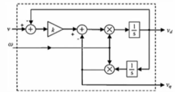
In virtual output impedance loop method, the derivative of output current may amplify the magnitude of harmonic currents. So this cannot be implemented if the harmonic content in the output current is high. This problem can be addressed by using SOGI. SOGI is basically a frequency adjustable resonant circuit and it is implemented by connecting two integrators in a cascaded manner to form a closed loop. The block diagram of SOGI is shown in fig.8.
Fig. 8: Block diagram of SOGI
SOGI has two inputs, one is actuating quantity, v, and the other, w frequency and produces two output signals Vd and Vq which will have a phase shift of 900. Here in this control, inverter output current is given as actuating
input and system frequency, the other input. So if the input to SOGI is I0=I sin(wt), then the two outputs are
given by the equations,
(14)
(15)
Now the virtual impedance loop can be implemented by using these two outputs. The time derivative of output current is given by,
(16) So the virtual impedance can be implemented simply by multiplying impedance values Z(s) with -Vq
(17)
Similarly virtual resistor can be implemented by multiplying virtual resistor value with the output of SOGI Vd.
(18)
Fig. 9: Implementation of virtual impedance using SOGI
Hence it can be observed that the derivative of output current is avoided and thus power sharing and stability in the MG are not affected by the nonlinear loads to a good extent. So if SOGI is used in conjunction with indirect operation of droop control method, further more accuracy in power sharing and stability of the MG can be enhanced.
The voltage reference obtained by indirect operation of droop control is modified to achieve accurate power sharing and stability by introducing virtual impedance drop through SOGI, as shown in fig .10. this modified voltage reference is used for pulse generation to trigger the inverters.
reactive power is tuned in such a way that the resulting voltage profile satisfies the real power. In the low voltage grid the reactive power is a function of phase angle and this is adjusted with the active power frequency droop. The block diagram of the proposed control is shown in fig 10.
Fig. 10: Block diagram of proposed control method using SOGI
6. Renewable Energy Sources 6.1 Photovoltaic System
A Photovoltaic (PV) system directly converts solar energy into electrical energy. The basic device of a PV system is the PV cell. Cells may be grouped to form arrays. The voltage and current available at the terminals of a PV device may directly feed small loads such as lighting systems and DC motors or connect to a grid by using proper energy conversion devices.
Fig. 11: Block diagram representation of Photovoltaic system
This photovoltaic system consists of three main parts which are PV module, balance of system
and load. The major balance of system
components in this systems are charger, battery and inverter. The Block diagram of the PV system is
shown in Fig.11. A. Photovoltaic cell A
photovoltaic cell is basically a semiconductor
diode whose p–n junction is exposed to light.
Photovoltaic cells are made of several types of
semiconductors using different manufacturing
processes. The incidence of light on the cell generates charge carriers that originate an electric current if the cell is short circuited 1
Fig. 12: Practical PV device
The equivalent circuit of PV cell is shown in the fig.3. In the above figure the PV cell is represented by a current source in parallel with diode. Rs and Rp represent series and parallel resistance respectively. The output current and voltage form PV cell are represented by I and V
7. Diode-Clamped Multilevel Inverter
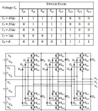
An m-level diode-clamped multilevel inverter typically consists of m – 1 capacitors on the dc bus and produces m levels of the phase voltage [4]. A three-phase five-level structure of a DCMLI is shown in Fig. 13. Each of the three phases of the inverter shares a common dc bus, which has been subdivided by four capacitors into five levels. The vo tage across each capacitor is Vdc, and the voltage stress across each switching device is limited to Vdc through the clamping diodes. Table II lists the output voltage levels possible for one phase of the inverter with the negative dc rail voltage V0 as a reference. State condition 1 means the switch is on, and 0 means the switch is off. Each phase has five complementary switch pairs such that turning on one of the switches of the pair requires that the other complementary switch be turned off. The complementary switch
pairs for phase leg a are (Sa1, Sa’1), (Sa2, Sa’2), (Sa3, Sa’3), and (Sa4, Sa’4). Table1 also shows that in a diode-clamped inverter, the switches that are on for a particular phase leg are always adjacent and in series.
Table 2: DCMLI voltage levels and switching states
The following are the some advantages and disadvantages of the DCMLI:
Advantages:
-As the number of levels increases the harmonic content of the output waveform decreases the filter size.
-Lower switching losses due to the devices being switched at the fundamental frequency without increasing the harmonic content in the output. -Reactive power flow can be controlled, as this does
not cause unbalance in the capacitor voltages.
-Fast dynamic response.
-Back to back operation is possible.
Disadvantages:
-High number of clamping diodes is required as the
number of levels increase.
-Active power transfer causes unbalance in the DC bus capacitors, this complicates the control of the system.
8. MATLAB/SIMULINK RESULTS
Fig. 14: Simulated model of proposed control strategy based
Fig. 15: Proposed control strategy
Fig. 16: Simulation output of P1 and Q1
Fig. 17: Simulated output wave form of P2 and Q2
Fig. 18: Inverter 1 output current and voltage
Fig. 19: Inv 2 voltage and current
Fig. 20: Frequency
Fig. 22: Simulink model of the Photo Voltaic Cell
Fig. 23: Simulated active and reactive power wave form of Photo Voltaic based Inverter
Fig. 24: Simulated active and reactive power wave form of full cell system
Fig. 25: Full cell voltage
Fig. 26: Matlab/Simulink model of a three-phase five-level diode-clamped multilevel inverter
Fig. 27: Output voltage of five level inverter with phase A
Fig. 28: THD of the five level inverter 9. Conclusion
References
[1] Guerrero JM, Chandorkar M, Lee TL, Loh PC. Advanced control architectures for intelligent micro grids- Part II: Power Quality, Energy Storage and AC/DC Micro grids. IEEE Trans. Ind. Electron. 2013; 60(4): 1263- 1270.
[2] Popov M, Karimi H, Nikkhajoei H, Terzija V. Dynamic Model and Control of a Micro grid with Passive Loads, IPST Conference Proceedings, 2009.
[3] Alabri RS, El-Saadany EF. Interfacing Control of Inverter-based DG Units, ICCCP-2009.
[4] Guerrero JM, Chandorkar M, Lee TL, Loh PC. Advanced control architectures for intelligent micro grids- Pqrt I: Decentralized and hierarchial control. IEEE Trans. Ind. Electron 2013; 60(4): 1254-1262.
[5] Wang X, Guerrero JM, Blaabjerg F, Chen Z. A Review of Power Electronics Based Micro grids. Journal of Power Electronics 2012; 12(1).
[6] Zhao-xia X, Hong-wei F. Impacts of P-f & Q-V Droop Control on Micro Grids Transient Stability. Physics Procedia 2012; 24: 276-282.
[7] Mitas J, Castilla M, Garcia de Vicuna L, Miret J. Virtual Impedance Loop for Droop-Controlled Single- Phase Parallel Inverters Using a
Second-Order General-Integrator Scheme. IEEE