International Journal of Emerging Technology and Advanced Engineering
Website: www.ijetae.com (ISSN 2250-2459, Volume 2, Issue 8, August 2012)177
Comparative Study of Wind Load Analysis of Flat Plate
Multistoried Frames With And Without Reinforced Concrete
Infilled Walls
P M B Raj Kiran Nanduri1, Dr. B. Dean Kumar 2, Y. Chandrasekhar3, Dr. B.L.P. Swami4
1
M.Tech Student, 2Associate Professor, Dept. of Civil Engineering, JNTUH, Hyderabad
3
Chief consultant, Sandilya Consulting Engineers, Hyderabad
4
Professor, Dept. of Civil Engineering, Vasavi College of Engineering Hyderabad
Abstract —Flat plate systems are a subset of the two-way slab family, meaning that the system deforms in two directions. Flat plate systems are reinforced concrete slabs of uniform thickness that transfer loads directly to supporting columns, and are distinguished from other two way systems by the lack of beams, column capitals, and drop panels.In tall multistoried structures the flat plate floor system has lack of resistance to lateral loads like wind, hence special features like shear walls, R.C. In-Filled Walls are to be provided if they are to be used in High rise constructions. In the present investigation numerical studies for 20,40,60,80 storied for frames with normal conventional beam supported slab system, flat plate floor system, flat plate floor system with R.C. In-filled walls has been conducted.
A Comparison of the Critical Column Axial Forces, Critical Column moments, Lateral Drift (in mm) due to static and wind loads on the structures located at Hyderabad at a basic wind speed of 44 m/s has been observed.
Keywords- Flat Plates; R.C. In-filled walls; Wind
I. INTRODUCTION
In general slabs are classified as being one-way or two-way. Slabs that primarily deflect in one direction are referred to as one-way slabs. When slabs are supported by columns arranged generally in rows so that the slabs can deflect in two directions, they are usually referred to as two-way slabs. Two-way slabs may be strengthened by the addition of beams between the columns, by thickening the slabs around the columns (drop panels), and by flaring the columns under the slabs (column capitals).
Flat Plates are solid concrete slabs of uniform depths that transfer loads directly to the supporting columns without the aid of beams or capitals or drop panels. Flat plates are probably the most commonly used slab system today for multi-storey reinforced concrete hotels, motels, apartment houses, hospitals, and dormitories. Flat plates can be constructed for a thickness of 125-250 mm for spans of 4.5-6 m. Flat Plate system have an advantage of introducing an edge beam at the periphery of the panel to reduce the deflection of the exterior panel of the plate.
The main disadvantage in Flat slabs and Flat plates is their lack of resistance to lateral loads, hence special features like shear walls, R.C. In-Fill Walls are to be provided if they are to be used in High rise constructions.
Glenn Morris, Husam Omar [1] studied about the Flat-plate reinforced concrete structures that tend to behave nonlinearly, even at service load levels, when subjected to lateral loading. Grossman [2] concludes that the flat plate system has a good resistance capacity for the lateral loads as well as gravity loads provided a proper detailing in the joint between the column and the slab. T. Stathopoulos, Y.S. Zhou [9] studied the numerical evaluation of wind pressures on flat roofs by using the Reynolds averaged Navier-Stokes equations and the standard k-ε turbulence model.
II. REINFORCED CONCRETE (R.C)IN-FILLED WALLS
Frame action provided by a flat slab–beam and column interaction is generally insufficient to provide the required strength and stiffness for buildings taller than about 10 stories. A system consisting of shear walls, R.C. Infill Walls and flat Plate-frames may provide an appropriate lateral bracing system.
In many cases, the existing concrete skeleton is stiffened by filling in the space between the beams and columns with masonry or cast-in-place concrete. These infill walls can be a cost-effective method of increasing the lateral strength and rigidity of the building.
International Journal of Emerging Technology and Advanced Engineering
Website: www.ijetae.com (ISSN 2250-2459, Volume 2, Issue 8, August 2012)178 Mehmet Emin Kara and Sinan Altin[6] investigated the behavior of non ductile reinforced concrete (RC) frames strengthened by introducing partial infill’s under cyclic lateral loading. Seven one-bay, two-storey, 1/3-scale test specimens were constructed and tested.
III. DETAILS OF THE PRESENT STUDY
In the present investigation 20, 40, 60 and 80 storied frames were analyzed using STAAD.PRO (V8i) software package. For each of the frame under consideration, three cases were considered. Case I: Normal conventional beam supported R.C. framed structure. Case II: Flat Plate R.C framed structure. Case III: Flat Plate R.C. framed structure with external infill walls.
All the three cases were considered for comparison with respect to the height of the structures. Comparisons was made with the Critical Column Axial Forces, Critical Column moments due to static and wind loads, Lateral Drift (in mm) in X, Z direction due to Wind loads. And also Strip moments (in Bending) in Flat Plates in both the Gravity and Wind loads on the structures located at Hyderabad at a basic wind speed of 44 m/s has been observed.
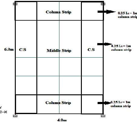
The total height of the frames considered for the study are of 62m, 124m, 186m, 248m respectively, which represents a 20,40,60,80 storied commercial building. The Plan area of the Structure is 40 m x 24 m with columns spaced at 6 m from center to center in Z-direction, 4 m from center to center in X-direction. The height of each storey is 3.10m and all the floors are considered as Typical Floors. The location of the building is assumed to be at Hyderabad. The plan view of a typical structure for 20 storey, 40 storey, 60 storey, 80 storey is shown in fig 1.
[image:2.612.332.558.315.521.2]s
Fig 1 Plan view of a typical structure for 20 storey, 40 storey, 60 storey, 80 storey structure
The column sizes for 20 storey, 40 storey, 60 storey, 80 storey are considered as 0.45m x 0.45m, 0.8m x 0.8m, 1.1m x 1.1m, 1.3m x 1.3m respectively. The edge beam sizes are considered as 0.25m x 0.45m, 0.35m x 0.6m, 0.45m x 0.75m, 0.55m x 0.9m respectively. The wind intensities are calculated as per IS: 875 (part 3). The wind intensities for 20 storey, 40 storey, 60 storey, 80 storey are considered as 1.789 kN/m2, 1.976 kN/m2, 2.092 kN/m2, 2.18 kN/m2 respectively.
[image:2.612.51.301.528.665.2]Each and every Flat plate panel of the building for 20 storey, 40-storey, 60-storey, 80-storey was properly meshed and the size of the meshes were maintained closer to aspect ratio 1 and the properly meshed Flat Plate panels are divided in to column strips and middle strips as shown in the figure 2.
Fig 2 Division of Meshed Flat Plate Panel in to column strips and middle strips.
International Journal of Emerging Technology and Advanced Engineering
Website: www.ijetae.com (ISSN 2250-2459, Volume 2, Issue 8, August 2012) [image:3.612.63.273.135.453.2]179
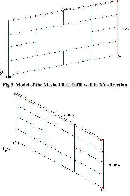
[image:3.612.333.555.331.479.2]Fig 3 Model of the Meshed R.C. Infill wall in XY-direction
Fig 4 Model of the Meshed R.C. Infill wall in YZ-direction
The R.C. Infill walls were positioned throughout the Periphery of each floor of the building for 20-storey, 40-storey, 60-40-storey, and 80-storey. The model of the R.C. Infill wall throughout the external periphery of the building is shown in the figure 5.
Fig 5 Model of the Peripheral R.C. Infill wall with central window opening throughout the external boundary
IV. VARIATION OF CRITICAL AXIAL FORCES WITH HEIGHT
Under factored Dead load & Live load the axial force at the base of the end column is highest in the Case I. It is true in the case of the all the four frames considered. The axial force in the remaining two cases i.e. Case II & Case III is considerably less when compared to Case I. This is because partition walls were considered in the first case. Hence for comparison purpose only second and third cases are considered under the vertical loads.
In all the buildings considered in the case of flat plate frames the end column is getting more axial force compared to the third case where in R.C. peripheral in filled walls is provided.
This is because the peripheral walls are considered as an integral element of the building and as such it contributes towards sharing of some of the axial Force.
0 5000 10000 15000 20000 25000 30000 35000 40000
0 10 20 30 40 50 60 70 80
B
a
se
A
xi
a
l
F
o
rc
e
in
kN
Number of storeys of the building
Case I
Case II
[image:3.612.52.290.535.653.2]Case III
Fig 6 Graph showing the comparison of Case I, Case II, Case III for Base End Column axial forces for 20, 40, 60, 80 storied building for
1.5(D.L+L.L)
In the Case III the axial compression at base on windward column of 20 story frame is reduced by nearly 35% when wind is considered. The reduction in the axial compression force in the end column in the Case III is nearly 61%. This is because of the interaction of the peripheral walls with the frame. Similarly same can be observed in the case of 40 and 60 storied frame.
International Journal of Emerging Technology and Advanced Engineering
Website: www.ijetae.com (ISSN 2250-2459, Volume 2, Issue 8, August 2012)180
0 5000 10000 15000 20000 25000 30000 35000 40000 45000 50000 55000 60000 65000
0 10 20 30 40 50 60 70 80
B
a
se
A
xi
a
l
F
o
rce
in
kN
Number of storeys of the building
Case I
Case II
[image:4.612.55.280.137.281.2]Case III
Fig 7 Graph showing the comparison of Case I, Case II, Case III for Base End Column axial forces for 20, 40, 60, 80 storied building for
1.2(D.L+L.L+W.LZ)
V. VARIATION OF CRITICAL MOMENTS WITH HEIGHT A.The Critical column base axial forces nearer to the R.C. In filled wall (Column 53) under gravity loads havebeen Studied.
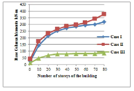
For end column of 40 storied building under gravity loading the column moments for Case I are less compared to Case II , where as the column moments for Case III are much lesser than in comparison with Case I and Case II.
It is observed that the column moments for Case II are increased by 20.04% compared to Case I, where as the column moments for Case III has decreased by 91.75 % & 90.11 % when compared with Case II, Case I.
For end column of 60 storied building under gravity loading the column moments for Case I are more compared to Case II, where as the column moments for Case III are much lesser than in comparison with Case I and Case II.
It is observed that the column moments for Case II are increased by 10 % compared to Case I, where as the column moments for Case III has decreased by 86.9 % & 85.45 % when compared with Case II, Case I.
For end column of 80 storied building under gravity loading the column moments for Case I are less compared to Case II, where as the column moments for Case III are much lesser than in comparison with Case I, Case II .
It is observed that the column moments for Case II are increased by 15.61% compared to Case II, where as the column moments for Case III decreased by 77.82 % & 73.72 % when compared with Case II, Case I.
Hence it is clear the third case consisting of flat plate system with R.C. In filled external peripheral wall (F.P.F.S+R.C.I) is more efficient against the gravity as well as wind loadings.
And the column moments in the first case i.e. Flat plate floor system are more because of absence of beams, R.C. In filled walls compared to 2nd case and 3rd case i.e. conventional, flat plate floor system.
Fig 8 Graph showing the comparison of Case I, Case II, Case III for Base End Column Moments for 20, 40, 60, 80 storied building for
1.5(D.L+L.L)
B.The Critical column base axial forces nearer to the R.C. In filled wall (Column 53) under wind loads have been Studied.
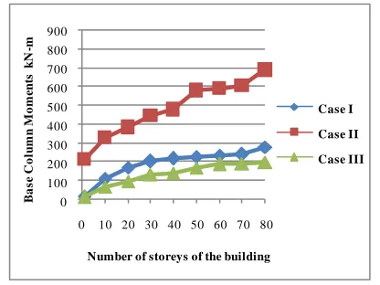
For end column of 40 storied building under wind loading the column moments for Case I are less compared to Case II, where as the column moments for Case III are much lesser than in comparison with conventional, flat plate floor system building.
It is observed that the column moments for Case II are increased by 40.95 % compared to Case I, where as the column moments for Case III has decreased by 94.02 % & 89.87 % when compared with Case II, Case I.
For end column of 60 storied building under wind loading the column moments for Case I are less compared to Case II, where as the column moments for Case III are much lesser than in comparison with Case I, Case II.
It is observed that the column moments for Case II are increased by 55 % compared to Case I, where as the column moments for Case III has decreased by 91 % & 81.8 % when compared with Case II, Case I.
For end column of 80 storied building under wind loading the column moments for Case I are less compared to Case II, where as the column moments for Case III are much lesser than in comparison with Case I, Case II.
[image:4.612.329.558.188.343.2]International Journal of Emerging Technology and Advanced Engineering
Website: www.ijetae.com (ISSN 2250-2459, Volume 2, Issue 8, August 2012)181 Hence it is clear the Case III consisting of flat plate system with R.C. In filled external peripheral wall (F.P.F.S+R.C.I) is more efficient against the gravity as well as wind loadings. And the column moments in the Case II are more because of absence of beams, R.C. In filled walls compared to 2nd case and 3rd case.
0 100 200 300 400 500 600 700 800 900
0 10 20 30 40 50 60 70 80
Ba
se
C
o
lum
n
M
o
m
ents
kN
-m
Number of storeys of the building
Case I
Case II
[image:5.612.327.559.124.301.2]Case III
Fig 9 Graph showing the comparison of Case I, Case II, Case III for Base End Column Moments for 20, 40, 60, 80 storied building for
1.2(D.L+L.L+W.LZ)
VI. VARIATION OF LATERAL DRIFT WITH HEIGHT
The most significant basic parameter monitored throughout the whole analysis process was drift at the top of the building for 20,40,60,80 storied buildings.
It can be seen that the value of drift in the direction of wind loading is more in the case of Case I. In case of Case II because of the additional lateral stiffness provided by flat plates the drift values are reduced.
In the case of a typical 60 storied building the drift value is reduced by 25% from Case I to Case II. Whereas the reduction in drift value is nearly 80 % from Case I to Case III. Similarly in the case of typical 80 storied building the drift value is reduced by 38.117% from Case I to Case II. Whereas the reduction in drift value is nearly 79 % from Case I to Case III. The other buildings also follow the same trend.
[image:5.612.64.272.212.368.2]In the case of tall multi storied buildings drift is a critical parameter to be considered in the design. Hence it is clear that Case II helps in reducing the drift in the case of multi storied building compared to Case I. The building can be further strengthened against the lateral loads by providing in filled walls also. The drift becomes minimum in this case.
Fig 10 Graph showing the comparison of lateral drift for 20, 40, 60, 80 storied building for 1.2(D.L+L.L+W.LZ)
VII. CONCLUSIONS
In the case of tall multi story frames consisting of flat plate floor system with R.C. in filled external peripheral wall (F.P.F.S+R.C.I) the column axial forces are very much reduced by nearly 36% in all the frames. Hence the design of column becomes economical.
It is observed that due to gravity loading the column moments for flat plate floor system building are increased by 15.52% compared to conventional building, where as the column moments for flat plate floor system building with
RC infill walls has decreased by 78.93 % & 74.90 % when compared with flat floor system , conventional beam supported slab system.
It is observed that due to wind loading the column moments for flat plate floor system building are increased by 43.04% compared to conventional building, where as the column moments for flat plate floor system building with RC infill walls has decreased by 84.15 % & 75.93 % when compared with flat floor system, conventional beam supported slab system.
International Journal of Emerging Technology and Advanced Engineering
Website: www.ijetae.com (ISSN 2250-2459, Volume 2, Issue 8, August 2012)182
The flat plate floor system helps in reducing the drift in the case of multi storied building compared to conventional beam slab column system. There is 31 % reduction in the drift in the case of flat plate floor system when compared to conventional beam supported slab system.
The flat plate floor system can be further strengthened against the lateral loads by providing in filled walls also. The drift becomes minimum, so that there is 79% reduction in the drift in this case.
By providing flat plate floor system instead of conventional system it is shown by the present analysis that the lateral stiffness of the building is increased. In addition, by providing in filled walls the building is made stiffer and the drift may become minimum.
It is recommended that provision of flat plate system within filled walls (or) shear walls is the best choice to safeguard the building against the lateral loads.
REFERENCES
[1] Glenn Morris, Husam Omar; Analysis of laterally loaded flat-plate structures, Canadian Journal ofstructural engineering, Vol.18, No.1, 1991, pp.109-117.
[2] Grossman JS, Verification of Proposed Design Methodologies for Effective Width of Slabs in slab-Column Frames, ACI Structural Journal 1997; Vol. 94, No. 5, pp. 181-196.
[3] sIS: 456(2000) “Plain and Reinforced concrete Structures – code of Practice (4th Revision)”, Bureau of Indian Standards, New
Delhi.2000.
[4] IS: 875(Part 3)-1987, “Code of Practise for Design Loads (Other than earthquakes) for Buildings and Structures”, Part 3 Wind Loads, Second Revision, Bureau of Indian Standards, New Delhi, 1989.
[5] Mark Fintel (Ed.), Handbook of Civil Engineering, Mark Fintel, Van Nostrand Reinhold, NewYork, 1974.
[6] Mehmet Emin Kara and Sinan Altin, Strengthening of RC non ductile frames with RC Infills : An Experimental Study, Science Direct, Cement and Composite journal, Vol.34, Issue.7, August 2008, pp 612-621.
[7] P.C.Varghese, “Advanced Reinforced Concrete Design (2009) “, PHI Publications Pvt.Ltd.
[8] S.Unnikrishna Pillai & Devdas Menon, “Reinforced Concrete Design”, Tata Mc Graw Hill Publications.