i
REVERSE ENGINEERING OF MICRO LIGHT AIRCRAFT
SYSTEMS AND DESIGN
WAN AZIZURRAHMAN BIN WAN HASSAN
A thesis submitted in
fulfillment of the requirement for the award of the
Degree of Master of Mechanical Engineering
FACULTY OF MECHANICAL AND MANUFACTURING ENGINEERING
UNIVERSITI TUN HUSSEIN ONN MALAYSIA
v ABSTRACT
vi ABSTRAK
vii CONTENTS TITLE DECLARATION DEDICATION ACKNOWLEDGEMENT ABSTRACT ABSTRAK CONTENTS
LIST OF FIGURES
LIST OF TABLES
LIST OF SYMBOLS AND ABBREVIATIONS
i ii iii iv v vi vii xi xvi xvii
CHAPTER 1 INTRODUCTION
1.1 Research background 1.2 Problems Statement 1.3 Research Objective 1.4 Scope of Study 1.5 Expected Outcome 1.6 Significant of Research
1 1 1 2 2 3 3
CHAPTER 2 THEORETICAL AND LITERATURE REVIEW
2.1 Reverse Engineering
2.1.1 Types of Reverse Engineering Techniques
2.1.2 Computer Aided Design (CAD) and Computer Aided Engineering (CAE) 2.2 Microlight Aircraft
2.2.1 History of Microlight Aircraft 2.2.2 Types of Microlight Aircraft 2.3 Quicksilver GT500 Microlight Aircraft
viii
2.3.1 Main Aircraft Component 2.3.2 The Wings – Structure 2.3.3 Fuselage
2.3.4 Empennage 2.3.5 Ailerons & Flaps 2.4 Materials
2.4.1 Aluminium
2.4.1 Aluminium Alloy 2024 2.4.2 Aluminium Alloy 6061 2.4.3 Aluminium Alloy 7075 2.4.2 Steel
2.4.3 Composite 2.4.4 Tubes
2.4.5 Bracing Cables 2.4.6 Bolts and Nuts
2.5 Manufacturing Process and Assembly Techniques
2.5.1 Bending 2.5.2 Hole Drilling 2.6 Structural Analysis
2.6.1 Engineering Stress 2.6.2 Engineering Strain
2.6.3 Young's Modulus - Modulus of Elasticity (or Tensile Modulus) - Hooke's Law
2.6.4 Shear Modulus 2.6.5 Von Mises Stress
2.6.5.1Distortion energy Theory 2.6.6 Principal Stress
2.7 Air-load Distributions
2.7.1 Schrenk’s Approximation Methods
ix
CHAPTER 3 METHODOLOGY
3.1 Assumptions
3.2 Specification of Quicksilver GT500 Microlight Aircraft
3.3 Data Acquisitions 3.4 Image Modelling 3.5 CAE Analysis
3.5.1 Selection of Material 3.5.2 Simplification of Analysis
3.5.3 Distributed Load on Aircraft Wing 3.5.4 Wing Loading Calculation
3.5.5 Determination of Constrain 3.5.6 Evaluation on Analysis 3.6 Selection of Material
42
43 43
44 45 46 48 48 49 51 52 53 53
CHAPTER 4 RESULTS AND DISCUSSIONS
4.1 Stress Load Analysis
4.1.1. Loads on the Aircraft
4.1.2. Determination of Center of Gravity 4.1.3. CADCAE Analysis
4.1.3.1. Stress Analysis for Wing Base Structure Using Aluminium 2024
4.1.3.2. Stress Analysis for Wing Base Structure Using Aluminium 6061
4.1.3.3. Stress Analysis for Wing Base Structure Using Aluminium 7050
4.2 Built up Material
54
55 56 58 59 60
64
68
x 4.2.1. Aluminium Alloy 4.2.2. Steel Alloy 4.2.3. Polymer 4.2.4. Composite 4.2.5. Fabric
4.3 Fasteners and Structural Joints 4.3.1. Aircraft Bolts and Nuts 4.3.2. Rivet
4.3.3. Weld Joints and Adhesive Bonding 4.4 Manufacturing Process
4.4.1. Bending 4.4.2. Drilling
4.5 Aircraft Control System 4.5.1. Flight Controls 4.5.2. Ground Control 4.5.3. Landing Gear 4.5.4. Fuel System 4.5.5. Brake System 4.5.6. Instrument Panel 4.5.7. Powerplant
75 77 78 79 80 81 82 83 85 86 86 87 88 89 90 91 91 92 93 94
CHAPTER 5 CONCLUSSION AND RECOMMENDATION
5.1 Conclusion
5.2 Suggestion for Improvement
95
95 96
REFERENCES
xi LIST OF FIGURES
Figure no. Title Page
1.1 2.1 2.2 2.3 2.4 2.5 2.6 2.7 2.8 2.9 2.10 2.11 2.12 2.13 2.14 2.15 2.16 2.17 2.18 2.19
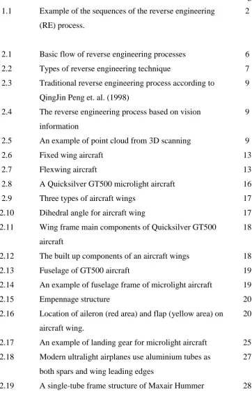
Example of the sequences of the reverse engineering (RE) process.
Basic flow of reverse engineering processes Types of reverse engineering technique
Traditional reverse engineering process according to QingJin Peng et. al. (1998)
The reverse engineering process based on vision information
An example of point cloud from 3D scanning Fixed wing aircraft
Flexwing aircraft
A Quicksilver GT500 microlight aircraft Three types of aircraft wings
Dihedral angle for aircraft wing
Wing frame main components of Quicksilver GT500 aircraft
The built up components of an aircraft wings Fuselage of GT500 aircraft
An example of fuselage frame of microlight aircraft Empennage structure
Location of aileron (red area) and flap (yellow area) on aircraft wing.
An example of landing gear for microlight aircraft Modern ultralight airplanes use aluminium tubes as both spars and wing leading edges
A single-tube frame structure of Maxair Hummer
[image:8.595.140.503.195.768.2]xii 2.20 2.21 2.22 2.23 2.24 2.25 2.26 2.27 2.28 2.29 3.1 3.2 3.3 3.4 3.5 3.6 3.7 3.8 3.9 ultralight
Cable construction is defined by number of strands and the number of wires per strand
Basics of bolts installation
The position of hole that can be drill on the aluminium tube of wing spar
Types of load acting on aircraft.
Condition of engineering stress in solid objects. Representation of a pure distortion case.
Stress boundary conditions on a 2 dimensional
element.
Stress boundary conditions in a 3 dimensional body and normal stress values induced in it.
Span-wise and chord-wise loadings on aircraft wing. Types of planform wing by aircraft manufacturers. Plan-form geometry for Schrenk’s method.
Reverse Engineering procedure for the project Quicksilver GT500 microlight aircraft.
GT500 mainframe structure.
The division of subsystem for Quicksilver GT500 microlight aircraft.
An example of CAD design performs using Autodesk Inventor 2012.
An example of stress analysis on aircraft structure that has been done by CAE software.
Flowchart diagram on engineering analysis for determination of material.
Load distribution on wing.
xiii 4.1 4.2 4.3 4.4 4.5 4.6 4.7 4.8 4.9 4.10 4.11 4.12 4.13 4.14 4.15 4.16 4.17
(a) Top view of CAD design for Quicksilver GT500 microlight aircraft structure. (b) Front view of CAD design for Quicksilver GT500 microlight aircraft structure. (c) Side view of CAD design for Quicksilver GT500 microlight aircraft structure. Total lift force, Ls distribution on the aircraft wing structure.
Wing spanwise lift distribution.
The CG location of Quicksilver aircraft wing determined by using CADCAE software.
Assembly of main wing structure and the loads acting on the structure.
Parts and components of wing structure that being replaced by 3 types of material for stress analysis. Result of stress analysis on wing structure using Aluminium 2024 material.
Displacement of structure using Aluminium 2024. Safety Factor of structure using Aluminium 2024. Result of stress analysis on wing structure using Aluminium 6061 material.
Displacement of structure using Aluminium 6061. Safety Factor of structure using Aluminium 6061 Result of stress analysis on wing structure using Aluminium 7050 material.
Displacement of structure using Aluminium 7050. Safety factor of structure using Aluminium 7050. Landing gear of GT500 model aircraft are made from high strength steel material.
The use of polymer material on aircraft bodyskin is more on windshield and safety door application.
xiv 4.18
4.19
4.20
4.21
4.22
4.23 4.24
4.25 4.26
(a) Seat bucket for pilot are made from composite materials. (b) Body skin of GT500 aircraft model are made from fibre glass material.
Wing skins of the aircraft are made from lightweight but high strength fabric material like Dacron.
The use of bolts and nuts are being applied on main structure joining for safety purpose. (a) An eyebolt is use to joint vertical stabilizer trailing edge and rudder leading edge assembly. (b) and (c) AN type hexagonal bolts and nuts are use to firmly joint the main
structures of the aircraft and received large amount of shear loading from the aircraft body weight. (d) Bolt loaded in double shear with associated bending due to load offset.
Riveting techniques are applied to join non-structural components of the aircraft. (a) Rivet joining on tail boom structure to hold empennage control parts. (b) Rivet is used to hold seat bracket in position on forward fuselage. (c) Rivet is used to assemble body skin to the tail boom tube.
An example of weld joint application on GT500 Quicksilver airplane as can be seen on rudder shaft joining.
Radius of tubing bending.
Location of the drilled holes must be at the centre of the tube structure.
GT500 aircraft surface control system.
A simple mechanical cable operated system found on Quicksilver GT500 aircraft. The cables in this aircraft sometimes are replaced by rods. The control column can be moved by raising and lowering the elevator.
79
81
83
83
86
87 88
xv 4.27
4.28
4.29
4.30
4.31 4.32
Location of (A) aileron and (B) wing flap as can be seen on figure above.
Two main wheels and tail skid are playing important role in landing situation while nose wheel give little support.
(a) The location of hand brake lever (inside yellow circle) which is on the right side of the pilots give confident to the pilot while landing the aircraft. (b) Mainwheel construction are made from reliable material to give extra safety to the pilot. The mainwheel braking systems are using disc and hydraulic clamping system.
An overview of pilot cockpit of GT500 aircraft. Basic controller indicator is as displayed on dashboard. Instrument panel layout for GT500.
A Rotax 582/40 rotary valve engine that powered the GT500 aircraft.
90
91
92
93
xvi LIST OF TABLES
Table no. Title Page
2.1 2.2 2.3 2.4 2.5 3.1 4.1 4.2 4.3 4.4 4.5 4.6 4.7 4.8 4.9
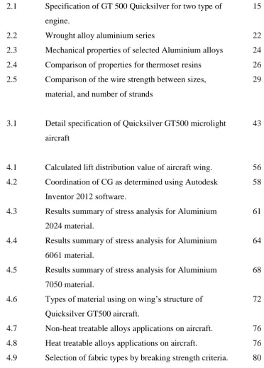
Specification of GT 500 Quicksilver for two type of engine.
Wrought alloy aluminium series
Mechanical properties of selected Aluminium alloys Comparison of properties for thermoset resins Comparison of the wire strength between sizes, material, and number of strands
Detail specification of Quicksilver GT500 microlight aircraft
Calculated lift distribution value of aircraft wing. Coordination of CG as determined using Autodesk Inventor 2012 software.
Results summary of stress analysis for Aluminium 2024 material.
Results summary of stress analysis for Aluminium 6061 material.
Results summary of stress analysis for Aluminium 7050 material.
Types of material using on wing’s structure of
Quicksilver GT500 aircraft.
Non-heat treatable alloys applications on aircraft. Heat treatable alloys applications on aircraft.
Selection of fabric types by breaking strength criteria.
xvii
LIST OF SYMBOLS AND ABBREVIATIONS
CAD Computer Aided Design CAE Computer Aided Engineering AoA angle of attack
MPa ksi
mega Pascals
kilopounds persquare inches CG center of gravity
CP center of pressure CAS calibrated airspeed
1
CHAPTER 1
INTRODUCTION
Reverse Engineering (RE) refers to the process of creating engineering design data from existing parts. It recreates or clones an existing part by acquiring the surface data of an existing part using a scanning or measurement device. It is useful in recreating the CAD model of an existing part when the engineering design is lost or when the model has gone through many design changes.
The application field of reverse engineering techniques are very wide. Many tools and methods had been introduced by researchers and engineers in order to propose the most economical ways of using reverse engineering techniques to the industry. In related mechanical areas like automotives and machineries, the used of reverse engineering become popular since it cost minimums and produce the results at shortest period of time compared to conventional R&D method.
2
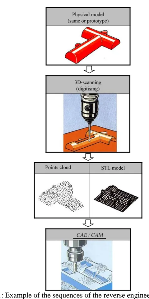
Figure 1.1: Example of the sequences of the reverse engineering (RE) process. (Sokovic and Kopac, 2006)
Another popular application of RE besides of engineering fields is in medical fields. The needs of reconstructing the bones of patients requires the doctors to do RE on the patient’s damage bones by using conventional and new technologies.
3 nowadays. Various kinds of requirement indirectly had boosted the introduction of new technologies in the market to fulfil them.
RE application in aircraft industries are very similar to automotives industry. The techniques and methods are same as both of them apply general engineering knowledge during the whole development of the product. Further explanations are as in Chapter 2 of this report.
1.1 Research Background
This research will focus on determining the possibility of using RE methods to identify the types of material and manufacturing process involved in fabricating a microlight aircraft. For this research, one model of microlight aircraft will be use as reference upon completing the RE processes. The comparative study will be carry out in terms of the cost of manufacture, time to produce and dimensioning accuracy of both existing and redesign aircraft models.
1.2 Problem Statement
Currently in Malaysia, aircraft industry is developing quite slow due to the high cost of producing aircraft and also limited acquisition of manufacturing technology. These constraints cause a lack of interest from investors to invest in the aeronautics industry. However, in other countries especially Europe, there are a lot of investor and small scale manufacturers who actively involve in producing microlight aircraft to fulfil the demands. To produce an aircraft, a lot of money needs to be invested and very time consuming. Besides, lack of knowledge and limited facilities are the main factors of inability to produce an aircraft in Malaysia.
4 material specifications, manufacturing and assembly process, and also the alternative design for the product.
1.3 Objectives
The objectives of this research are as follows:
1. To model aircraft mainframe using CAD software. 2. To determine the materials used for structural and skin.
3. To identify the manufacturing methods/ techniques to produce the structural frame.
1.4 Scope of Study
The research is limited according to the scopes below:
1. The study of microlight aircraft subsystems is to understand the critical loads effect on structural beam.
2. The reference microlight aircraft is Quicksilver GT500.
3. The structural analysis is implemented by using Autodesk Inventor 2012. 4. The CAD model of the aircraft is developed by using Autodesk Inventor
2012.
1.5 Research Contribution
This research has able to accumulate a comprehensive information on the reference microlight aircraft into CAD modelling, acquire information on built up materials, and related manufacturing process to produce the aircraft.
1.6 Significant of Research
5
CHAPTER 2
THEORETRICAL AND LITERATURE REVIEW
Reverse Engineering (RE) refers to the process of creating engineering design data from existing parts. It recreates or clones an existing part by acquiring the surface data of an existing part using a scanning or measurement device. According to Peng and Loftus (1998), RE is useful in recreating the CAD model of an existing part when the engineering design is lost or when the model has gone through many design changes.
2.1 Reverse Engineering
Reverse engineering and rapid prototyping of objects with complex surfaces have received significant attention from both research and industrial communities nowadays. This is happening mainly because of growing global competition that requires manufacturers to deliver more competitive products with better quality and lower prices. Reducing the product development time had become a challenging tasks faced by manufacturing industry. The demanding and competition exist all over the world since most of countries had practice open-air economic system.
6 engineering backward to build a CAD model geometrically identical to an existing product. As shown in Figure 2.1, Lee and Yoo (2000) define the reverse engineering as the backward process used to recover higher level conceptual elements from physical systems.
In normal automated manufacturing environment, the operation sequence usually starts from product design via computer-aided design (CAD) techniques, and ends with generation of machining instructions required to convert raw material into a finished product. In contrast to this conventional manufacturing sequence, reverse engineering represents an approach for the new design of a product that lacks an existing CAD model.
[image:20.595.114.532.468.544.2]In the process of the product design and research, the use of RE will largely reduced the production period and costs. Unlike the traditional manufacturing philosophy of designs being transposed into products, reverse engineering measures, analyses, modifies, and produces the products based on existing artifacts (Vergeest and Horvath, 2009). Using 3D point data collected by contact or non-contact method, a CAD model can be created and employed in subsequent manufacturing processes.
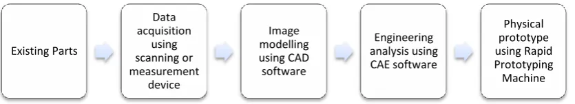
Figure 2.1: Basic flow of reverse engineering processes. (Lee and Yoo, 2000)
Yang and Chen (2005) had presented a new reverse engineering methodology based on haptic volume removing. By using a haptic device, the number of view changes could also be reduced and operating time be shortened. However, the limitation of the workpiece size to be measure makes it impossible to be applied on large size objects. The accuracy of the mirror image still considers low since it is dependent on the voxel resolutions.
Existing Parts
Data acquisition
using scanning or measurement
device
Image modelling using CAD software
Engineering analysis using CAE software
7 The success of reverse engineering is that it not only generates accurate mathematical computer-aided design (CAD) models for design and manufacturing purposes, but can significantly reduce product design lead time.
Reverse engineering always come together with rapid prototyping (RP) technology. Jain and Kuthe (2013) in their publication had mention about a dominant technology for producing physical models for testing and evaluation purposes has been RP. The rapid prototyping processes can be broadly classified into processes that uses laser and ones which does not. RP in other word is a tool or medium to complete the reverse engineering process (Kumar and Kruth, 2010)
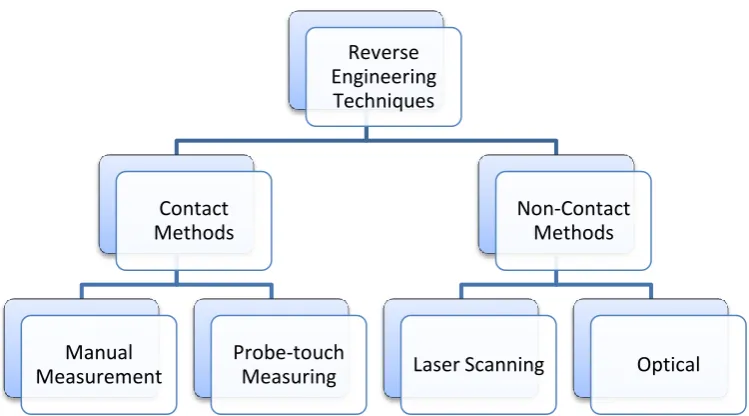
2.1.1 Types of Reverse Engineering Technique
[image:21.595.118.493.543.751.2]The acquisition, analysis and transfer of technical data are the key elements of reverse engineering. Figure 2.2 shows the hierarchy of reverse engineering techniques which can be divided into two major groups; non-contact and contact method. Many researchers had published their works about the method of RE. Xinming et al. (2001) mentioned about applying a vision-sensor technique to gain data or digitizing on free-form surface before transferring them into CAD software. Dubravcik and Kender (2012) stressed the importance of 3D scanning techniques for reverse engineering process in automotives industries and can save a lot of time in design development.
Figure 2.2: Types of reverse engineering technique. Reverse
Engineering Techniques
Contact Methods
Manual Measurement
Probe-touch Measuring
Non-Contact Methods
8
Contact methods consist of using electro-mechanical equipment such as force- sensitive touch probes to mapping the coordinate of the objects surface. One of many popular devices from this category is Coordinate Measuring Machines (CMM). CMM is used for data acquisition of products, especially in the aeronautical and automotive industries where complex surfaces are frequently encountered. Peng and Loftus (1998) mentioned about the important of CMM as the key provider for dimensional inspection (see Figure 2.3). However, high cost of the co-ordinate measuring equipment, supporting software and the time to recover surface details by the measurement process are disadvantages of this technology. In addition, the use of touch-trigger probe technology on the current generation of CMMs may have the following drawbacks:
Damaging the product surface.
Misleading readings owing to the deflection of the probe and/or part.
Erroneous calculation of probe tip compensation.
9
[image:23.595.114.525.240.330.2]Figure 2.3: Traditional reverse engineering process according to Peng and Loftus (1998)
Figure 2.4: The reverse engineering process based on vision information according to Peng and Loftus (1998)
Li et al. (2002) in their report explained about new scanning technologies that have potential to further enhance the quality of 3D object scans. One such development is non-contact scanning systems employing white light rather than a single laser tracking line. This kind of laser technology generates dense volumetric scans where the detailed scans can be generated quickly, and the wide scanning volume reduces the importance of the angle at which the tracking light hits the target object. Fastest and in machine industry most used are laser and optical 3D scan devices. (Dubravcik and Kender, 2012). These devices allow us to scan shapes of the real parts with machine industry precision demands.
[image:23.595.224.412.606.732.2]10 2.1.2 Computer Aided Design (CAD) and Computer Aided Engineering
(CAE) Software
Complex CAD designs like a whole aircraft cannot be designed as one part. A huge amount of data, components and parts have to be organised in a smart way. Basically these designs can be split into parts and assemblies where assemblies are built of several parts. If a value changes in one part, this can have an impact to other parts. For example, if the position of the wings should be modified, it is not sufficient to send this information to the electronic assembly of the wings since the fuselage section with the wing box also needs to move, and depending on the level of detail that is reached, it might be necessary to move a lot of reinforcing elements. An associative model allows interrelating different geometric objects. If the position of the wings changes, also the wing box, the fuselage, and the fairing are automatically adapted to the new situation.
Redesign the large component like aircraft need powerful CAD software to support the thousands of parts to be assembled. Not many CAD software are able to provide the large amount of memory capacity to run the hundreds of 3D component at same time. Barbero (2009) had mentioned about an alternative method for recovering a damage product by using CAD software instead of applying complex mathematical algorithms. Besides, the designers need to use a powerful and high performance computer to do design task of this kind of project. Just to name a few, CAD software like CATIA, SOLIDWorks, Unigraphics, and ProE are among top medium to be use by designer in heavy industries like automotives.
11 movement of the product, assembly the product, and even analysis the physical limit of the product. Engineering analysis like stress analysis, flow analysis, impact analysis, and heat transfer analysis plays a vital role in determining the most suitable design of the product. Besides, this kind of analysis also will help the designer to develop safety procedure of their product simultaneously.
2.2 Micro Light Aircraft
According to Gratton (1999), microlight aircraft are defined as aeroplanes having no more than two seats, minimum flying speed in the landing configuration at maximum take-off mass (VSO) not exceeding 35 knots CAS (calibrated air speed) and a maximum take-off mass of no more than:
i. 300 kg for a landplane, single seater, or ii. 450 kg for a landplane, two-seater, or
iii. 330 kg for an amphibian or floatplane, single seater, or iv. 495 kg for an amphibian or floatplane, two seater.
There are three control systems used in this class of aircraft: these are three axis controlled (conventional aeroplane controls); weight shift controlled and powered parachutes (the last of these using an enlarged paraglide-style wing). The weightshift-controlled microlight aeroplane also referred to in the UK as the ‗flexwing‘ or in the USA as the ‗trike‘, is the most numerous type of microlight
aircraft ever manufacture.
This class of aircraft is controlled by direct application of pitching or rolling moments to the wing through a control bar, with the mass of the ‗trike‘ unit
suspended below the wing providing the necessary reaction. This means that, from the pilot‘s perspective, the bar is pushed to starboard to roll to port, and forwards to
12 2.2.1 History of Microlight Aircraft
In the 1960s, a NASA research scientist name Francis Rogallo had designed a collapsible delta wing which would deploy from within the hull of the shuttle after re-entry. His design proposal had been rejected by the NASA and the idea stopped at the moment. However, some of aviation enthuasiasts in USA saw the Rogallo‘s wing
idea as a potential for leisure flying. So, they developed his design into the first delta wing glider, and the sport of hang glider had been born. This kind of aircraft later becomes quickly popular to the extreme sportsman around the world.
Almost immediately, some of the early hang gliding pioneers tried various ways of attaching power units to their wings so they could take off without first having to climb to the top of a hill. After all kinds of experimentation, the forerunners of the modern flexwing microlight took to the skies in the early 1970s. Since that time, wing and airframe/engine technology has moved on rapidly. Today's factory-manufactured microlights, powered by a choice of reliable two-stroke and four-stroke engines, are the result of years of design improvements within a framework of strict safety regulations.
In the last few years microlights have circumnavigated the globe and set new world records. Despite their fragile appearance, modern microlight aircraft are incredibly strong and have one of the best safety records in leisure aviation.
2.2.2 Types of Microlight Aircraft
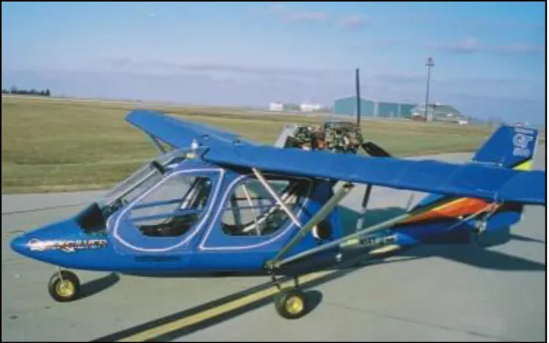
13 The fixed wing market is divided into home built and kit built aircraft, regulated by the Popular Flying Association (PFA) and factory built planes which are regulated by the British Microlight Aircraft Association (BMAA). The price difference between the kit built and factory aircraft are not great such as kit plane may take some 500 hours to build. Some fixed wing aircraft are difficult to rig and are therefore best kept in a hangar or on some sort of trailer.
Figure 2.6: Fixed wing aircraft.
(http://www.somersetmicrolights.org.uk/aircraft_text.htm)
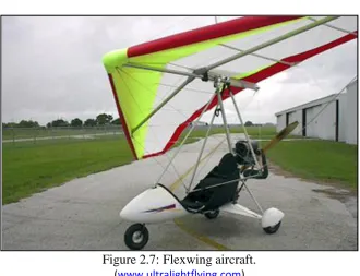
Figure 2.7: Flexwing aircraft. (www.ultralightflying.com)
[image:27.595.154.485.393.646.2]14 the 'trike' unit so that wherever the weight of the trike is put, the aircraft will roll or pitch in that direction. These inputs are made via a single horizontal bar in front of the pilot. The flexwing has a more 'open to the elements' feel than a fixed wing and is much simpler in construction. This allows it to be easily dismantled by one person to fit on a small trailer in around half an hour. Although it is possible to build a flexwing yourself, it is very rarely done as there very few kits currently on the UK market, so almost all flexwings are factory built and regulated by the BMAA.
The flexwing has no rudder therefore has no yaw control which makes it a little more difficult to land in a crosswind. The fixed wing aircraft has a rudder so can be kicked straight when landing, however the flexwing's lack of rudder and tail means it cannot spin.
2.3 Quicksilver GT 500 Microlight Aircraft
The Quicksilver GT500 (Figure 2.8) is a family of strut-braced, with high wing, pusher configuration, tricycle gear aircraft built by Quicksilver Manufacturing of Temecula, California. The aircraft is available as a kit for amateur construction or as a completed ready-to-fly. The GT500 was developed specifically for the Sportplane class of the primary aircraft category (Part 21.24 of the Federal Aviation Regulations), and on 26 July 1994 became the first aircraft certified in that category. The aircraft's nomenclature is unclear as the manufacturer variously refers to it as the GT500, GT 500 and the GT-500. The FAA certification officially calls it the GT500 (Cliche et al., 2001).
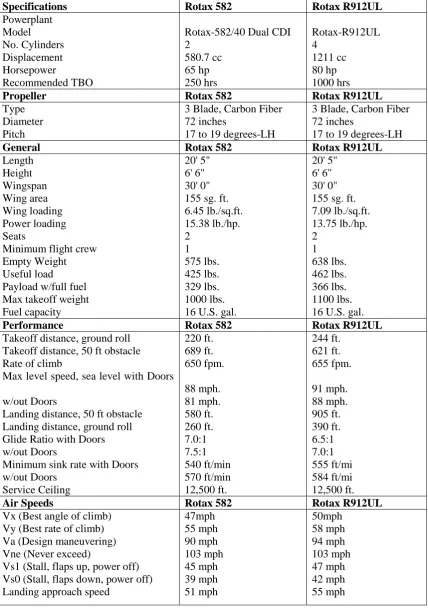
15 Table 2.1: Specification of GT 500 Quicksilver for two type of engine.
(http://www.fpna.com/gt500.htm)
Specifications Rotax 582 Rotax R912UL
Powerplant Model No. Cylinders Displacement Horsepower Recommended TBO
Rotax-582/40 Dual CDI 2 580.7 cc 65 hp 250 hrs Rotax-R912UL 4 1211 cc 80 hp 1000 hrs
Propeller Rotax 582 Rotax R912UL
Type Diameter Pitch
3 Blade, Carbon Fiber 72 inches
17 to 19 degrees-LH
3 Blade, Carbon Fiber 72 inches
17 to 19 degrees-LH
General Rotax 582 Rotax R912UL
Length Height Wingspan Wing area Wing loading Power loading Seats
Minimum flight crew Empty Weight Useful load Payload w/full fuel Max takeoff weight Fuel capacity
20' 5" 6' 6" 30' 0" 155 sg. ft. 6.45 lb./sq.ft. 15.38 lb./hp. 2 1 575 lbs. 425 lbs. 329 lbs. 1000 lbs. 16 U.S. gal.
20' 5" 6' 6" 30' 0" 155 sg. ft. 7.09 lb./sq.ft. 13.75 lb./hp. 2 1 638 lbs. 462 lbs. 366 lbs. 1100 lbs. 16 U.S. gal.
Performance Rotax 582 Rotax R912UL
Takeoff distance, ground roll Takeoff distance, 50 ft obstacle Rate of climb
Max level speed, sea level with Doors
w/out Doors
Landing distance, 50 ft obstacle Landing distance, ground roll Glide Ratio with Doors w/out Doors
Minimum sink rate with Doors w/out Doors Service Ceiling 220 ft. 689 ft. 650 fpm. 88 mph. 81 mph. 580 ft. 260 ft. 7.0:1 7.5:1 540 ft/min 570 ft/min 12,500 ft. 244 ft. 621 ft. 655 fpm. 91 mph. 88 mph. 905 ft. 390 ft. 6.5:1 7.0:1 555 ft/mi 584 ft/mi 12,500 ft.
Air Speeds Rotax 582 Rotax R912UL
Vx (Best angle of climb) Vy (Best rate of climb) Va (Design maneuvering) Vne (Never exceed)
Vs1 (Stall, flaps up, power off) Vs0 (Stall, flaps down, power off) Landing approach speed
16 2.3.1 Main Aircraft Component
An aircraft is conceived as a complete structure, but for manufacturing purposes must be divided into sections, or main components, which are in turn split into sub-assemblies of decreasing size that are finally resolved into individual detail parts. Each main component is planned, tooled and built as a separate unit and joined with the others in the intermediate and final assembly stages. In design stages, six subsystem of aircraft normally being set up which are fuselage, empennage, wings, landing gear, engine, and aileron and flaps division.
[image:30.595.168.471.382.571.2]Figure 2.8 shows a typical weightshift microlight aircraft (a Quicksilver GT500). The aircraft comprises two distinct parts, the fuselage and the wing. While the interaction between them is essential to the characteristics of the aircraft, it is convenient initially to consider them separately.
Figure 2.8: Quicksilver GT 500 microlight aircraft.
2.3.2 The Wing – Structure
17
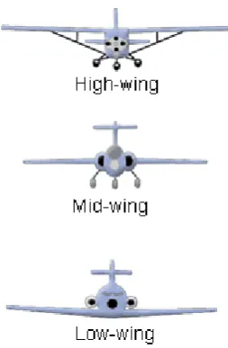
[image:31.595.255.382.90.284.2]Figure 2.9: Three types of aircraft wings.
Figure 2.10: Dihedral angle for aircraft wing.
The wing structure of a fixed-wing microlight (see Fig. 2.11) is complex and somewhat unlike that of a conventional wing. The primary parts of the structure are the leading edges two segmented tubes typically 4.5–5.0 m long, which are joined at the nose to the keel tube which runs the length of the wing and can be seen protruding from the trailing edge in Figure 2.8. Stretched over these is the sail manufactured from a high strength synthetic non-porous fabric such as polyester Dacron. The whole structure is put under considerable internal loads during rigging, rigidity and form being ensured by cross-tubes, which are hinged at approximately half-span to the leading edges and hinged to each other above the keel tube.
18
[image:32.595.132.508.242.461.2]Figure 2.11: Wing frame main components of Quicksilver GT500 aircraft.
Figure 2.12: The built up components for an aircraft wing.
2.3.3 Fuselage
The fuselage is the main body structure to which all other components are attached. The fuselage contains the cockpit or flight deck, passenger compartment and cargo compartment. While wings produce most of the lift, the fuselage also produces a little lift. A bulky fuselage can also produce a lot of drag. For this reason, a fuselage is streamlined to decrease the drag. Most of us usually think of a streamlined sports car as being sleek and compact - it does not present a bulky obstacle to the oncoming wind. A streamlined fuselage has the same attributes. It has a sharp or rounded nose with sleek, tapered body so that the air can flow smoothly around it.
19 frame structure are the combination of aluminium tube, rectangular shape tube, and also some pieces of aluminium plates that joint together by bolts and nuts. The simple design of the fuselage can assure the lightness of the aircraft weight without compromising the safety level. Figure 2.14 shows the example of fuselage structure for microlight aircraft which is built by using aluminium tubes.
[image:33.595.213.426.382.527.2]Figure 2.13: Fuselage of GT500 Quicksilver aircraft.
Figure 2.14: An example of fuselage frame of microlight aircraft. (http://www.ultralightnews.com/)
2.3.4 Empennage
20
Figure 2.15: Empennage structure
The vertical tail structure is divided into the vertical stabilizer and the rudder. The front section is called the vertical stabilizer and is used to prevent the aircraft from yawing back and forth. The principle behind its operation is much like the principle of a deep keel on a sailboat. In light, single-engine aircraft, it also serves to offset the tendency of the aircraft to roll in the opposite direction in which the propeller is rotating. The rear section of the vertical structure is the rudder. It is a movable airfoil that is used to turn the aircraft.
2.3.5 Ailerons & Flaps
Ailerons are hinged control surfaces attached to the trailing edge of the wing of a fixed-wing aircraft. The ailerons are used to control the aircraft in roll. The two ailerons are typically interconnected so that one goes down when the other goes up: the downgoing aileron increases the lift on its wing while the upgoing aileron reduces the lift on its wing, producing a rolling moment about the aircraft's longitudinal axis. The word aileron is French for ‗little wing‘. While flaps are an aerodynamic devices found at the trailing edges of aircraft wings, used to augment lift at a lower speed during takeoff and landing. (refer to Figure 2.16)
21
2.4 Materials
Historically, one of the most thorough evaluations of the competition between materials was performed by the aerospace industry. It is not uncommon for commercial grade materials and components to be used in this class of aeroplane. For the aerospace industry, aluminium airplanes proved to be much lighter than steel airplanes. (Patton et al., 2004). The fuselage structure of most modern aircraft comprises curved aluminium alloy skin panels, which are fixed to stiffening members called frames and stringers, which provide radial and longitudinal stiffness, respectively. Previous technique in joining the structure was by riveting the steel to the mainframe. However, after the introduction of aluminium welding, there has been growing interest in the welding of aerospace aluminium alloys (Simmons and Schleyer, 2006). Aluminium, steel, and titanium will probably continue to be the principal material in airframe design for a while. All these material however, will have to be improved (Chun-Yung, 1999).
2.4.1 Aluminium
Aluminium alloy are the most commonly used airframe material because of their low densities, excellent range of properties which can be matched to particular requirements, experience of manufacturing techniques and the known in service behaviour (Howe, 2004). According to Mouritz (2012), series of aluminium alloys of 2xxx, 3xxx, 5xxx, 6xxx, and 7xxx are widely used in aviation. The 2xxx series is recommended for operation at high working temperatures and with high destruction viscosity rates. 7xxx series alloys – for operation at lower temperatures of highly-loaded parts and for parts with high resistance to corrosion under stress. For less loaded components, 3xxx, 5xxx, and 6xxx series alloys are used.
22 have the significant advantages for this application of better corrosion resistance and reduced cost. 6000 series alloys can be used simply anodised. High strength alloys are occasionally used to save weight in high stress areas (such as wing spars).
[image:36.595.109.527.331.722.2]6000 series alloys are most commonly used in the T6 temper: solution heat-treated and artificially aged. 6061-T6 is the traditional North American specification with a minimum ultimate tensile strength of 290MPa. 6082-T6 (formerly HT30TF) is the traditional British specification with a minimum ultimate tensile strength of 310MPa. (Syson, 2011). The summary of aluminium alloys are given in Table 2.2. The main alloying element(s) is used to determine into which one of the eight series an alloy is allocated.
Table 2.2: Wrought alloy aluminium series. (Mouritz, 2012) Alloy series Main alloying
element (s)
Temper process Application(s)
1000 Commercially pure
Al (>99% Al)
Not-age hardenable
Unsuaitable to used as structural materials on aircraft, sometimes used as sircraft fuel tanks, fairings, oil tanks, repair material of wing tips and tanks
2000 Copper Age-hardenable Used in many structural and semistructural
components in aircraft. Also used in damage-tolerant applications such as lower wing skins and fuselage structure of commercial aircraft which require high fatigue resistance.
3000 Manganese Not-age
hardenable
Rarely used in aircraft, sometimes used as nonconstructural material in fairing, fillets, tanks, wheel pants, nose bowls and cowlings
4000 Silicon Age-hardenable
(if magnesium present)
Limited due to brittle silicon phase that can form in the aluminium matrix which reduces the ductility and fracture toughness.
5000 Magnesium Not-age
hardenable
Used occasionally in nonconstructural aircraft parts such as wing ribs, wing tips, stiffeners, tanks, ducting, and frameworks.
6000 Magnesium and
silicon
Age-hardenable Used in wide range of non-aerospace components, such as buildings, rail cars, boat hulls, ship superstructures and in automotive components. Rarely used in aircraft component.
7000 Zinc Age-hardenable most common aluminium alloys used in
aircraft for structure building due to carry higher stress than 2000 series alloy.
8000 Other (including
lithium)
Mostly age-hardenable
23 2.4.1.1 Aluminium Alloy 2024
Known as the ―aircraft alloy‖ in machining rod, this alloy has properties higher than
2017 and 2014. Even though its form ability is generally considered only fair in the cold state, Al2024 is one of the most popular alloys for cold heading and roll threading applications. This alloy can be machined to a high finish and corrosion resistance is fair. Among popular applications include Phillips head screws, wood screws, hydraulic fittings and small parts in clocks and meters. It is also the basic alloy for cold finished rectangular bar where strength and machinability are essential for precision fittings and parts.
2.4.1.2 Aluminium Alloy 6061
Al6061 is generally selected where welding or brazing is required, or for its particularly high corrosion resistance in all tempers. It is one of the most common alloys of aluminium for general purpose use. Even though it performs low in machining process, its weight is lighter than Al2024. Among popular applications from this material include railway car components, bridge components, pipe fittings, wheels and various transportation end uses. This alloy is generally use in construction of aircraft structures, such as wings and fuselages, and more commonly in homebuilt aircraft than commercial or military aircraft.
2.4.1.3 Aluminium Alloy 7075
24
Table 2.3: Mechanical properties of selected Aluminium alloys. (http://asm.matweb.com/)
Mechanical Properties
Al2024 Al6061 Al7075
Hardness, Brinell 120 95 150
Ultimate Tensile
Strength
469 MPa 310 MPa 572 MPa
Tensile Yield Strength 324 MPa 276 MPa 503 MPa
Elongation at Break 19 % 12 % 11 %
Modulus of Elasticity 73.1 GPa 68.9 GPa 71.7 GPa
Poisson's Ratio 0.33 0.33 0.33
Fatigue Strength 138 MPa 96.5 MPa 159 MPa
Shear Modulus 28 GPa 26 GPa 26.9 GPa
Shear Strength 283 MPa 207 MPa 331 MPa
Machinability 70 % 50 % 70 %
Density 2.78 g/cc 2.7 g/cc 2.81 g/cc
2.4.2 Steel
Steel has several advantages over aluminium where it is three times as strong and can be welded easily into complex shapes that are far more durable than a bolted or riveted aluminium structure. Like aluminium, steel alloys are identified by a four-digit code that specifies the alloying components.
The used of steel in aircraft is usually confined to safety-critical structural components that require very high strength and where space is limited. In other words, steel is used when high specific strength is the most important criterion in materials selection. Steels used in aircraft have yield strength above 1500-2000 MPa, which is higher than high strength aluminium (500-650 MPa), titanium (830-1300 MPa) or quasi-isotropic carbon epoxy composite (750-1000 MPa). In addition to high strength, steels used in aircraft have high elastic modulus, fatigue resistance and fracture toughness, and retain their mechanical performance at high temperature (up to 300-450 °C). This combination of properties makes steel a material of choices for heavily loaded aircraft structures.
REFERENCES
Barbero, B.R. (2009). The recovery of design intent in reverse engineering problems. Computers & Industrial Engineering 56, pp. 1265–1275
Chun-Yung, M.N. (1999). Airframe Structural Design: Practical design information and data on aircraft structures. 2nd Edition. Hong Kong Conmilit Press Ltd.
Cliche, A. (2001). Ultralight Aircraft Shopper's Guide. 8th Edition. Cybair Limited Publishing. pp B-95.
Crane, D. (2006). Aviation Mechanic Handbook. 5th Edition. Aviation Supplies & Academics.
Dubravcik, M. & Kender, S. (2012). Application of reverse engineering techniques in mechanics system services. Procedia Engineering 48, pp. 96 – 104
Gratton G.B. (1999). The weightshift-controlled microlight aeroplane. British Microlight Aircraft Association, The Bullring, Deddington, Banbury,
Oxfordshire OX15 0TT, UK.
Jain, P. & Kuthe, A.M. (2013). Feasibility Study of manufacturing using rapid prototyping: FDM Approach. Procedia Engineering 63, pp. 4 – 11
Kumar, S. & Kruth, J. P. (2010). Composites by rapid prototyping technology. Materials and Design 31, pp. 850–856
Ledermann, C., Hanske, C., Wenzel, W., Ermanni, P., Kelm, R. (2005). Associative parametric CAE methods in the aircraft pre-design. Aerospace Science and Technology 9, pp. 641–651
Li, L., Schemenauer, N., Peng, X., Zeng, Y. & Gu, P. (2002). Areverse engineering system for rapid manufacturing of complex objects. Robotics and Computer Integrated Manufacturing 18, pp. 53–67
Lin, Y.P., Wang, C.T., & Dai, K.R. (2005), Reverse engineering in CAD model reconstruction of customized artificial joint. Medical Engineering & Physics 27. pp. 189–193.
Howe, D. (2004). Aircraft Loading and Structural Layout. Professional Engineering Publishing.
Kroes, M. & Rardon, J. (1993). Aircraft: Basic Science, Student Guide, 7th Edition. McGraw Hill Company.
Mouritz, A.P. (2012). Introduction to Aerospace Materials. Woodhead Publishing.
Niu, CY Micheal. (1999). Airframe Structural Design. 2nd Edition. Hong Kong Conmilit Press Ltd.
Park, H.S. & Dang, X.P. (2010). Structural optimization based on CADCAE integration and metamodeling techniques. Computer-Aided Design 42, pp. 889-902
Patton, R., Fang, L., Edwards, M. (2004). Causes of weight reduction effects of material substitution on constant stiffness components. Thin-Walled Structures 42, pp. 613–637
Peng, Q.J. & Loftus M. (1998). A new approach to reverse engineering based on vision information. International Journal of Machine Tools & Manufacture 38, pp. 881–899
Simmons, M.C., Schleyer, G.K. (2006). Pulse pressure loading of aircraft structural panels. Thin-Walled Structures 44, pp. 496–506
Syson, B. (2011). Bolted Aluminium Tube Construction for Minimum Aeroplanes, Light Aircraft Design Conference. Royal Aeronautical Societies.
Vergeest, J.S.M. & Horvath, I. (1999). Practical and commutational issues of reverse/forward engineering of shape. Reverse engineering: 3D scanning and a shortcut to modeling, Aarhus: Danish Technological Institute, pp. 1–6
Wanttaja, R.J. (2006). Kit Airplane Construction. 3rd Edition. McGraw Hill Company.
Xinmin, L., Zhongqin, L., Huang, T., & Zeng, Z. (2001). A study of reverse engineering system based on reverse sensor for free form surfaces. Computers & Industrial Engineering 40. pp. 215-227
Yang, Z. & Chen, Y. (2005). A reverse engineering method based on haptic volume removing. Computer-Aided Design 37, pp. 45–54
http://www.beliteaircraft.com/ultralight-aircrafts/Superlite-WoW-Belte.php
http://www.fpna.com/gt500.htm
http://www.lightsportaircraftpilot.com/
http://www.somersetmicrolights.org.uk/aircraft_text.htm
http://www.somersetmicrolights.org.uk/aircraft_text.htm
http://www.ultralightnews.com/
www.avidflyeraircraft.com