DIGITAL INSTRUMENT DISPLAY FOR CARS
SITI MARIAM BINTI HUSSAIN
This Report Is Submitted In Partial Fulfillment Of Requirements For The Bachelor Degree Of Electronic Engineering with Honours (Industrial Electronic)
Fakulti Kejuruteraan Elektronik dan Kejuruteraan Komputer Universiti Teknikal Malaysia Melaka
ii
UNIVERSITI TEKNIKAL MALAYSIA MELAKA
FAKULTI KEJURUTERAAN ELEKTRONIK DAN KEJURUTERAAN KOMPUTER BORANG PENGESAHAN STATUS LAPORAN
PROJEK SARJANA MUDA II
Tajuk projek : Digital Instrument Display For Cars Sesi pengajian : 2006/2007
Saya SITI MARIAM BINTI HUSSAIN (HURUF BESAR)
Mengaku membenarkan laporan Sarjana muda ini disimpan di perpustakaan dengan syarat-syarat seperti berikut:
2. perpustakaan dibenarkan membuat salinan untuk tujuan pengajian sahaja
3. perpustakaan dibenarkan membuat salinan laporan sebagai pertukaran antara institusi pengajian tinggi. 4. Sila tandakan ( √ )
( Mengandungi maklumat yang berdarjah keselamatan atau SULIT* kepentingan Malaysia seperti yang termaktub di dalam AKTA
RAHSIA RASMI 1972)
( Mengandungi akta maklumat TERHAD yang telah ditentukan oleh TERHAD* organisasi/badan di mana penyelidikan di jalankan.
TIDAK TERHAD
Disahkan oleh:
___________________ __________________________ (TANDATANGAN PENULIS) (COP DAN TANDATANGAN PENYELIA) Alamat tetap: D/A Kedai Mustafa, Kg. Kemayang,
Tawang, 16020 Bachok, Kelantan.
Tarikh: 27 April 2007 Tarikh: 27 April 2007
iii
DECLARATION
“I admit that this is done by myself except the discussion and extracts taken from other sources that I explained each in detail.”
Signature :
iv
SUPERVISOR APPROVAL
“I admit that I have read this literature work through my observation which has fulfilled the scope and quality in order to be qualified for the conferment of Bachelor Degree in
Electronic Engineering with Honours (Industrial Electronic)”
Signature :
v
DEDICATION
vi
ACKNOWLEDGEMENTS
vii
ABSTRACT
viii
ABSTRAK
ix
TABLE OF CONTENTS
CHAPTER DESCRIPTION PAGE
PROJECT TITLE
REPORT STATUS APPROVAL FORM
DECLARATION iii
SUPERVISOR APPROVAL iv
DEDICATION v
ACKNOWLEDGEMENTS vi
ABSTRACT vii
ABSTRAK viii
TABLE OF CONTENTS ix
LIST OF TABLES xii
LIST OF FIGURES xiii
LIST OF ABBREVIATIONS xv
LIST OF APPENDIXS xvii
I INTRODUCTION
1.1 Introduction Of The Project 1
1.2 Project Objective 2
1.3 Problem Statement 2
1.4 Scope Of Works 3
1.5 Method Of Project 4
x
II LITERATURE REVIEW
2.1 Analog-to-digital Converter 6 2.2 Successive Approximation ADC 7 2.3 Practical Considerations Of ADC Circuits 9
2.4 Introduction Of PIC16F84 11
2.5 Pin Description 13
2.6 Seven-Segment Display (Multiplexing) 14 -programming example
2.7 PIC Programmer 21
2..7.1 Flash PIC USB Programmer Electronic Kit 21 2.7.2 Programmer For A Broad Range PC Processors 22
III PROJECT METHODOLOGY
3.1 Project Overview 23
3.2 Project Plan And requirement 24 3.2.1 Components Selection 25 3.2.2 Construct And Test 25
3.3 Methodology Analysis 26
3.3.1 PIC Microcontroller 26 3.3.1.1 PIC 16F84A Main Features 27
3.3.2 Source Code 30
3.3.3 7-segment LED Display 30
3.3.4 Truth Table of 7-Segment display 32 (Common-Anode)
3.4 Project Design And Implementation 33
3.4.1 Hardware 33
3.4.1.1 Component List 35
3.4.1.2 Circuit Details 38
xi
3.4.1.4 Presentation 39
3.4.1.5 Different Modes 39
3.4.1.6 A-D converter 41
3.4.1.7 LED Displays 43
3.4.1.8 Display Dimming 44
3.4.1.9 Mode Switches 45
3.4.1.10 Power 45
3.4.1.11 PCB Design 46
3.4.1.12 Component Placement And 48 Soldering Process
3.4.2 Software 50
3.4.2.1 Workflow Of Program The PIC 51 3.4.2.2 Flow Chart Of Digital Instrument Display 52
IV RESULT AND ANALYSIS
4.1 Circuit Test 53
4.1.1 Circuit Testing Analysis 56
4.2 Programming Testing 56
V DISCUSSION AND CONCLUSION
5.1 Discussion 61
5.2 Project Improvement And Suggestions 62
5.3 Conclusion 62
REFERENCES 63
xii
LIST OF TABLES
NO TITLE PAGE
3.1 Selected tools and components for project design 25 3.2 Connection of PIC pin with 7-segment display 32 3.3 Truth table of 7-segment display (Common anode) 33
3.4 Component list 36
xiii
LIST OF FIGURES
NO TITLE PAGE
1.1 Diagram of process 3
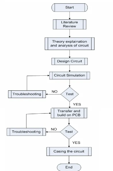
1.2 Flow chart of brief methodology 4
2.1 Block Diagram of ADC 7
2.2 Successive approximation 8
2.3 Successive approximation ADC 9
2.4 Example of ADC used 10
2.5 Harvard vs. von Neuman block architecture 12
2.6 PIC16F84 pins diagram 13
2.7 7-segment display 14
2.8 Connecting a microcontroller to 7-segment display in multiplex mode 16 2.9 Flash PIC USB Programmer Electronic Kit 21 2.10 Programmer for a broad range PC processors 22 3.1 Block diagram for project major elements 23 3.2 Block diagram for project methodology 24 3.3 Pin diagrams for PIC16F84A 27
3.4 PIC16F84A block diagram 28
3.5 7-segment dimensions 31
xiv 3.11 PCB design for microcontroller board 47 3.12 Component placement of microcontroller board 48 3.13 Component placement of display board 48 3.14 Soldering of display board 49 3.15 Soldering of microcontroller board 49 3.16 Workflow diagram for complete operation of PIC 51 3.17 Flow chart of digital instrument display 52 4.1 Voltage measurement at pin 4 54 4.2 Voltage measurement at pin 14 54
4.3 Display testing 55
4.4 Choosing the appropriate microcontroller 57 4.5 Selecting a language toolsuite 57
4.6 Naming the project 58
xv
LIST OF ABBREVIATIONS
PIC - Peripheral Interface Controller PCB - Printed Circuit Board
LCD - Liquid Crystal Display LED - Light Emitting Diode
ADC - Analog To Digital Converter PWM - Pulse Width Modulation BCD - Binary Code Decimal
SAR - Successive-Approximation Register RAM - Random Access Memory
CPU - Central Processing Unit SMD - Surface Mount Devices DIP - Dual In Package
Dp - Decimal Point
POV - Persistance Of Vision PC - Personal Computer
RISC - Reduce Instruction Set Computer ICSP - In-Circuit Serial Programming POR - Power-on Reset
PWRT - Power-up Timer OST - Oscillator Start-up Timer WDT - Watchdog Timer ASM - Assembly Language DC - Direct Current
xvi
REF - Reference
IC - Integrated Circuit
GND - Ground
xvii
LIST OF APPENDIXS
NO TITLE PAGE
A Program Of The Project 64
B Datasheet PIC16F84A 74
CHAPTER I
INTRODUCTION
1.1 Introduction Of The Project
Most cars have analogue readouts for displaying fuel level and engine temperature. The oil pressure is either shown on an analogue gauge or more commonly, there is no gauge but just an “idiot” warning light. There is nothing wrong with analogue gauges. Some drivers would rather have these outputs displayed in digital format. That is where this Digital Instrument Display comes in.
2 going. As an example, remaining fuel level somewhere between full and half-empty or temperature midway between hot and cold. By contrast, it can calibrate this digital display unit to show the actual values. The Digital Instrument Display is calibrated at two values and the instrument calculates the remaining values from these in a linear fashion. For example, if the unit is to be used as a fuel gauge, it is best calibrated when the fuel tank is full and then calibrated when the tank is close to empty. The display will then subsequently be able to show the remaining fuel in the tank over the complete range from full to empty.
1.2 Project Objective
To design the Digital Instrument Display circuit that can:
¾ Convert the analogue display in cars to a digital display. In order to ensure that the project objectives are met:
• To be able to program Peripheral Interface Controller (PIC) microcontroller: - As an analog to digital converter
- To display the digital value by BCD 7-segment.
1.3 Problem Statement
3
1.4 Scope Of Works
Input sensing circuit Output
Part 1 Part 2
Figure 1.1 : Diagram of process
This project is divided into two parts, the first part is the controller circuit using PIC (Microchip Peripheral Interface Controller). The second part is the digital instrument display circuit. The operation of the product will be controlled by a PIC. For the PIC, program will be written using assembly language and burnt. The digital instrument display circuit will be then be constructed. Testing and calibration on real hardware will be carried out to ensure it is functionally correct.
4
[image:21.612.119.513.86.680.2]1.5 Method Of Project
5
1.6 Thesis Outline
This report is divided into several chapters. They are I. Introduction
II. Literature Review III. Project Methodology IV. Result and Discussion V. Conclusion and Suggestion
This thesis represent by five chapters. Chapter I will focus on brief introduction of the project carried. The important overview or description including the problem statement, project objectives and project scopes are well emphasized in this part.
Chapter II will be based on the literature review of the project. It is mainly focused on the analog to digital converter, PIC16F84A and about seven-segment display (multiplexing). It also defined the details including PIC programmer.
Chapter III will explain on the concepts, theories and principle used in order to complete the project. This part consists of the methodology and also the information on research, experiment and simulation carried during the project development.
Chapter IV mainly focused on the result and analysis done using the device. All testing and verification result are attached with the aid of figure, table and statistic related to the project.
CHAPTER II
LITERATURE REVIEW
2.1 Analog-to-digital Converter
An analog-to-digital converter (abbreviated ADC, A/D or A to D) is an
electronic circuit that converts continuous signals to discrete digital numbers. Typically, an ADC is an electronic device that converts an input analog voltage to a digital number. The digital output may be using different coding schemes, such as binary and two's complement binary. However, some non-electronic or only partially electronic devices, such as shaft encoders, can also be considered as ADCs.
7
Figure 2.1 : Block Diagram of ADC
2.2 Successive Approximation ADC
The successive-approximation converter is one of the most widely used types of ADC. One method of addressing the digital ramp ADC's shortcomings is the so-called successive-approximation ADC. The only change in this design is a very special counter circuit known as a successive-approximation register. Instead of counting up in binary sequence, this register counts by trying all values of bits starting with the most-significant bit and finishing at the least-most-significant bit. Throughout the count process, the register monitors the comparator's output to see if the binary count is less than or greater than the analog signal input, adjusting the bit values accordingly. The way the register counts is identical to the "trial-and-fit" method of decimal-to-binary conversion, whereby different values of bits are tried from MSB to LSB to get a binary number that equals the original decimal number. The advantage to this counting strategy is much faster results.