HEAT DRIVEN ABSORPTION COOLING SYSTEMS
by
ROBERTO BEST Y BROWN
Thesis submitted for the degree of Ph.D.
Department of Chemical & Gas Engineering University of Salford
ENGLAND
1990.
i V viii
xix
xxi NOMENCLATURE
LIST OF TABLES
LIST OF FIGURES
ACKNOWLEDGMENTS
ABSTRACT
CHAPTER 1 INTRODUCTION AND PERSPECTIVES FOR HEAT
PUMPS IN MEXICO 1
1.1 ENERGY RESERVES 1
1.2 NEED FOR HEAT PUMP TECHNOLOGY 1
1.3 SOLAR COOLING 2
1.4 GEOTHERMAL COOLING 3
1.5 PROSPECTS FOR HEAT PUMPS 4
1.6 REFERENCES 6
CHAPTER 2 HEAT PUMPS 7
2.1 TYPES OF HEAT PUMPS 7
2.1.1 Vapour compression heat pumps 7 2.1.2 Vapour jet heat pumps 7
2.1.3 Thermoelectric heat pumps 8 2.1.4 Absorption heat pumps 8 2.1.5 Compression-absorption heat
pumps 8
2.1.6 Absorption-resorption heat
pumps 9
2.1.7 Heat of reaction chemical heat
Page No. 2.2 HEAT PUMPS IN PROCESS APPLICATIONS 10 2.3 SOLAR ENERGY AS HEAT SOURCE FOR
ABSORPTION COOLING SYSTEMS 10 2.4 GEOTHERMAL ENERGY AS HEAT SOURCE FOR
ABSORPTION COOLING SYSTEMS 12
2.5 REFERENCES 13
CHAPTER 3 THERMODYNAMIC CONSIDERATIONS FOR ABSORPTION
HEAT 'PUMPS 21
3.1 HEAT PUMPS 21
3.2 MECHANICAL VAPOUR COMPRESSION SYSTEMS 22 3.3 HEAT DRIVEN ABSORPTION SYSTEMS 23
3.3.1 Conventional absorption heat
pumps 23
3.3.2 Ideal coefficient of performance of an absorption system 25 3.3.3 Enthalpy based coefficient of
performance 26
3.4 HEAT TRANSFORMERS 28
3.5 WORKING FLUID PAIRS FOR ABSORPTION
SYSTEMS 29
3.5.1 Working fluid-absorbent
combinations 29
3.5.2 Properties of the working fluid 29 3.5.3 Properties of the absorbent 30 3.5.4 Criteria common to all fluids 31
4
ABSORPTION HEAT PUMPS 38
4.1 INTRODUCTION 38
4.2 IDEAL COEFFICIENT OF PERFORMANCE OF AN
ABSORPTION COOLING SYSTEM 39
4.3 IDEAL COEFFICIENT OF PERFORMANCE OF AN
ABSORPTION HEATING SYSTEM 40
4.4 COEFFICIENT OF PERFORMANCE OF AN
ABSORPTION HEAT TRANSFORMER 40
4.5 THERMODYNAMIC PROCESS DESIGN DATA FOR
AMMONIA-WATER FOR COOLING 41
4.6 THERMODYNAMIC PROCESS DESIGN DATA FOR
AMMONIA-WATER FOR HEATING 42
4.7 THERMODYNAMIC PROCESS DESIGN DATA FOR AMMONIA-WATER FOR COOLING AND
SIMULTANEOUS HEATING 43
4.8 THERMODYNAMIC PROCESS DESIGN DATA FOR
AMMONIA-LITHIUM NITRATE FOR COOLING 44
4.9 THERMODYNAMIC PROCESS DESIGN DATA FOR
AMMONIA-LITHIUM NITRATE FOR HEATING 44
4.10 THERMODYNAMIC PROCESS DESIGN DATA FOR
AMMONIA-LITHIUM NITRATE FOR COOLING AND
SIMULTANEOUS HEATING 45
4.11 THERMODYNAMIC PROCESS DESIGN DATA FOR
AMMONIA-WATER FOR HEAT TRANSFORMERS 45
4.12 THERMODYNAMIC PROCESS DESIGN DATA FOR
AMMONIA-LITHIUM NITRATE FOR HEAT
4.13 DISCUSSION OF THERMODYNAMIC PROCESS
DESIGN DATA 47
4.14 THE IMPORTANCE OF DERIVED THERMODYNAMIC
DATA 47
4.15 CONCLUSIONS 48
4.16 REFERENCES 49
CHAPTER 5 MODELLING OF CONTINUOUS ABSORPTION COOLING
SYSTEMS 78
5.1 INTRODUCTION 78
5.2 THERMODYNAMIC CONSIDERATIONS 78 5.3 THERMODYNAMIC PROPERTIES OF THE
AMMONIA-WATER MIXTURES 81
5.4 MASS AND ENERGY BALANCES FOR THE
AMMONIA-WATER ABSORPTION SYSTEM 81 5.5 MASS AND ENERGY BALANCES FOR THE
AMMONIA-LITHIUM NITRATE ABSORPTION
SYSTEM 84
5.6 RESULTS AND DISCUSSION 87
5.7 CONCLUSIONS 90
5.8 REFERENCES 92
CHAPTER 6 EXPERIMENTAL STUDIES ON THE PERFORMANCE OF THE
ABSORBER OF AN ABSORPTION COOLING SYSTEM 105
6.1 INTRODUCTION 105
6.2 THERMODYNAMIC CONSIDERATIONS 106
6.3 EXPERIMENTAL 108
6.4 RESULTS 109
6.5 CONCLUSIONS 110
CHAPTER 7 A STUDY ON THE OPERATING CHARACTERISTICS OF AN EXPERIMENTAL ABSORPTION COOLER USING
TERNARY SYSTEMS 118
7.1 INTRODUCTION 118
7.2 EXPERIMENTAL 120
7.3 RESULTS AND DISCUSSION 121
7.4 CONCLUSIONS 123
7.5 REFERENCES 125
CHAPTER 8 EXPERIMENTAL STUDIES WITH AN AMMONIA-WATER ABSORPTION SYSTEM USING A FALLING FILM
GENERATOR FOR SOLAR COOLING 137
8.1 INTRODUCTION 137
8.2 DESIGN CONSIDERATIONS 138
8.3 EQUIPMENT DETAILS 138
8.4 EXPERIMENTAL PROCEDURE 141 8.5 RESULTS AND DISCUSSION
141
8.6 CONCLUSIONS 143
8.7 REFERENCES 144
CHAPTER 9 EXPERIMENTAL STUDIES WITH AN AMMONIA-WATER ABSORPTION SYSTEMS OPERATING ON LOW ENTHALPY
GEOTHERMAL ENERGY 157
9.1 INTRODUCTION 157
9.2 EXPERIMENTAL FOR INSTALLATION AT LOS
AZUFRES 158
9.2.1 Equipment 158
9.2.3 Results and discussion for
installation at Los Azufres 161 9.3 EXPERIMENTAL FOR INSTALLATION AT CERRO
PRIETO 163
9.3.1 Equipment 163
9.3.2 Results and discussion for
installation at Cerro Prieto 164
9.4 CONCLUSIONS 166
9.5 REFERENCES 167
CHAPTER 10 CONCLUSIONS AND RECOMMENDATIONS 185
10.1 CONCLUSIONS 185
10.2 RECOMMENDATIONS 188
APPENDIX 1 DERIVED THERMODYNAMIC DESIGN DATA FOR
ABSORPTION HEAT PUMP SYSTEMS 190
APPENDIX 2 RAW EXPERIMENTAL DATA 287
BIBLIOGRAPHY 348
A cross sectional area of absorber, m2
C heat capacity per unit mass of solution, kJ kg-1 K-1 (COP) coefficient of performance, dimensionless
(COP) A actual coefficient of performance, dimensionless
.(CCP)ACL actual coefficient of performance for cooling, dimensionless
(COP) AH actual coefficient of performance for heating, dimensionless
(COP) AT actual coefficient of performance for a heat transformer, dimensionless
(COP) c Carnot coefficient of performance, dimensionless (COP)CL coefficient of performance for cooling,
dimensionless
(C")CCL Carnot coefficient of performance for cooling, dimensionless
(COP) cH Carnot coefficient of performance for heatingj dimensionless
(COP)CT Carnot coefficient of performance for a heat transformer, dimensionless
(COP)ECL enthalpy based coefficient of performance for cooling, dimensionless
(COP) ER enthalpy based coefficient of performance for heating, dimensionless
(COP) ET enthalpy based coefficient of performance for a heat transformer, dimensionless
ETA1 economiser efficiency, dimensionless ETA2 precooler efficiency, dimensionless (FR) A actual flow ratio, dimensionless (FR) flow ratio, dimensionless
II enthalpy per unit mass, kJ kg
-1 -mass transfer coefficient, mh1 mass flow rate, kg s-1 or kg h-1
MAM mass flow rate of ammonia, kg s -1
M
L mass flow rate of solution, kg h
• Mw mass flow rate of water as working fluid kg h-1 N
D refractive index, dimensionless (N)
GE generator efficiency, dimensionless
(N)REC recuperator (economiser) efficiency, dimensionless pressure, bar or MPa
P
AB pressure in absorber, bar pressure in condenser, bar CO
P
EV pressure in evaporator, bar P
GE pressure in generator, bar P
R pressure of refrigerant, bar P
REC pressure in rectifier, bar heat load, W or kW
QAB heat load in absorber, W or kw heat load in condenser, W ot kW CO
QEV heat load in evaporator W or kW QGE heat load in generator W or kW Q
REC heat load in rectifier, W or kW Q1 heat load in economiser, W or kW Q11 heat load in precooler, W or kW
temperature, °C or K
T' refrigerant temperature, °C T
AB temperature in absorber, °C CO temperature in condenser, °C T
EV temperature in evaporator, °C GE temperature in generator, °C T
REC temperature in rectifier, °C
rate of work delivered to the shaf of compressor, W or kW
rate of work delivered by solution pump, W or kW X weight fraction, or weight percent, dimensionless X equilibrium concentration of water at the bulk
absorber solution temperature and pressure, weight fraction, dimensionless
X
B actual concentration of water at the bulk absorber solution temperature and pressure, weight fraction, dimensionless
X
R concentration of refrigerant at condenser outlet, weight fraction, dimensionless
GREEK LETTERS
density, kg m-3
SUBSCRIPTS
A actual
AB absorber
AM ammonia
CO condenser
GS cold storage
DE desorption
E enthalpy
FD feed solution to absorber
EV evaporator
GE generator
H heating
HS heat source
L solution
R refrigerant
RE resorption
REC rectifier
RF ref lux
W water
WAB water to absorber
Table 8.1 Operating conditions of the ammonia-water
refrigeration prototype. 146
Table A1.1 Derived thermodynamic design data for absorption systems operating on
ammonia-water for cooling. 190
Table A1.2 Derived thermodynamic design data for absorption systems operating on
ammonia-water for heating. 201
Table A1.3 Derived thermodynamic design data for absorption systems operating on
ammonia-water for cooling and simultaneous heating. 210
Table A1.4 Derived thermodynamic design data for absorption systems operating on
ammonia-lithium nitrate for cooling. 219
Table A1.5 Derived thermodynamic design data for absorption systems operating on
ammonia-lithium nitrate for heating. 240
Table A1.6 Derived thermodynamic design data for absorption systems operating on ammonia-lithium nitrate for cooling and simultaneous
Page No. Table A1.7 Derived thermodynamic design data for 266
absorption heat transformers operating on ammonia-water.
Table A1.8 Derived thermodynamic design data for absorption heat transformers operating on
ammonia-lithium nitrate. 274
Table A2.1 Raw experimental performance data for the operating characteristics of the
water-lithium bromide absorption cooler. 287
Table A2.2 Raw experimental performance data for the operating characteristics of the water-lithium bromide-zinc bromide absorption
cooler. 290
Table A2.3 Raw experimental performance data for the operating characteristics of the water-lithium bromide-water-lithium iodide absorption
cooler. 294
Table A2.4 Raw experimental performance data for the operating characteristics of the ammonia-water absorption refrigerator operated with geothermal steam at Los Azufres, Michoacan,
Page No. Table A2.5 Raw experimental performance data for the
operating characteristics of the
ammonia-water absorption system at UNAM. 302
Table A2.6 Raw experimental performance datn for the operating characteristics of the ammonia-water absorption refrigerator at the
LIST OF FIGURES Page No.
2.1 Mechanical vapour compression heat pump 16
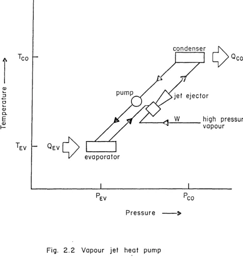
2.2 Vapour jet heat pump 17
2.3 Absorption heat pump 18
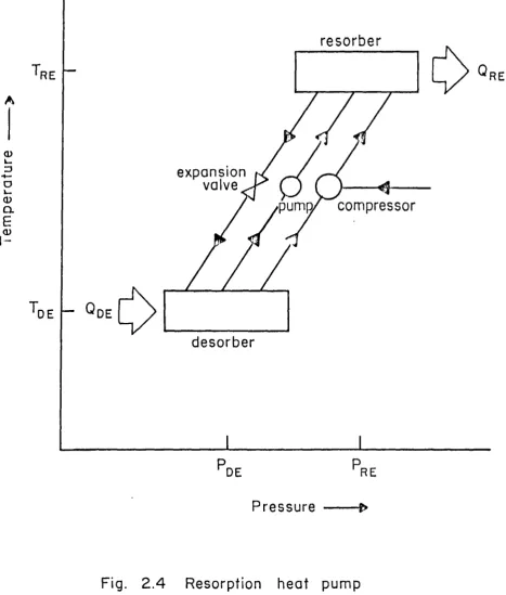
2.4 Resorption heat pump 19
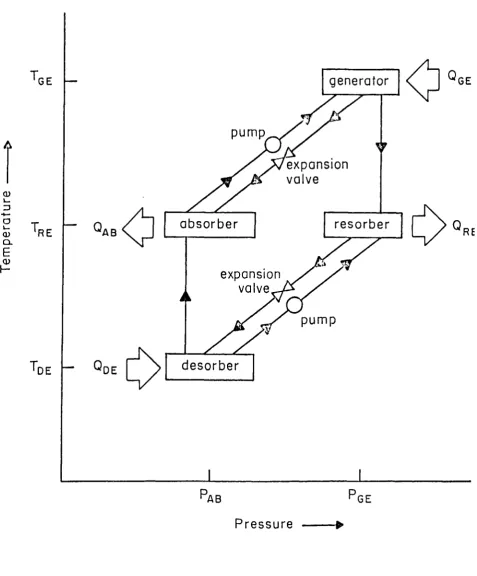
2.5 Absorption-resorption heat pump 20
3.1 Mechanical vapour compression heat pump 34
3.2 Absorption heat pump 35
3.3 Schematic diagram for a conventional
absorption heat pump 36
3.4 Simplified block diagram for a basic
absorption heat transformer 37
4.1 Simplified block diagram for a basic
absorption heat pump 51
4.2 Absorption cycle on an equilibrium chart
for the ammonia-water system 52
4.3 Simplified block diagram for a basic
absorption heat transformer 53
4.4 Plot of coefficients of performance and flow ratio against generator temperature
at three different absorber temperatures 54 4.5 Plot of coefficients of performance and
flow ratio against condenser temperature
at three different absorber temperatures 55 4.6 Plot of coefficients of performance and
flow ratio against evaporator temperature
Page No.
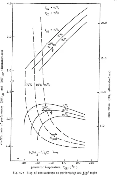
4.7 Plot of coefficients of performance and
flow ratio against generator temperature
at three different absorber temperatures 57
4.8 Plot of coefficients of performance and
flow ratio against condenser temperature
at three different absorber temperatures 58
4.9 Plot of coefficients of performance and
flow ratio against evaporator temperature
at three different absorber temperatures 59
4.10 Plot of coefficient of performance and
flow ratio against generator temperature
at three different absorber temperatures 60
4.11 Plot of coefficients of performance and
flow ratio against condenser temperature
at three different absorber temperatures 61
4.12 Plot of coefficients of performance and
flow ratio against evaporator temperature
at three different absorber temperatures 62
4.13 Plot of coefficients of performance and
flow ratio against generator temperature
Page No. 4.14 Plot of coefficients of performance and
flow ratio against condenser temperature
at three different absorber temperatures 64
4.15 Plot of coefficients of performance and flow ratio against evaporator temperature
at three different absorber temperatures 65
4.16 Plot of coefficients of performance and flow ratio against generator temperature
at three different absorber temperatures 66
4.17 Plot of coefficients of performance and flow ratio against condenser temperature
at three different absorber temperatures 67
4.18 Plot of coefficients of performance and flow ratio against evaporator temperatUre
at three different absorber temperatures 68
4.19 Plot of coefficients of performance and flow ratio against generator temperature
at three different absorber temperatures 69
4.20 . Plot of coefficients of performance and flow ratio against condenser temperature
Page No. 4.21 Plot of coefficients of performance and
flow ratio against evaporator temperature
at three different absorber temperatures 71
4.22 Plot of coefficients of performance and ' flow ratio against absorber temperature at three different temperatures of the
evaporator and generator 72
4.23 Plot of coefficients of performance and flow ratio against absorber temperature at three different temperatures of
condenser 73
4.24 Plot of coefficients of performance and flow ratio against generator temperature at three different temperatures of the
absorber 74
4.25 Plot of coefficients of performance and flow ratio against absorber temperature
at three different condenser temperatures 75
4.26 Plot of coefficients of performance and flow ratio against absorber temperature
95
96
97 Page No. 4.27 Plot of coefficients of performance and
flow ratio against generator temperature
at three different absorber temperatures 77
5.1 Ammonia—water absorption refrigeration
system 93
5.2 Ammonia—lithium nitrate absorption
refrigeration system 94
5.3 Coefficient of performance (COP) ECL against generator temperature (TGE) at different condenser temperatures for ammonia—water
5.4 Coefficient of performance (COP) ECL against generator temperature (T GE ) at different condenser temperatures
(Tco)
for ammonia—lithium nitrate5.5 Coefficient of performance (COP) ECL against generator temperature (
Page No.
5.6 Coefficient of performance (COP) ECL against generator temperature
(T GE ) at different absorber temperatures (TAB)
for ammonia-lithium nitrate 98
5.7 Coefficient of performance (COP) ECL ngainst generator temperature for both ammonia-water and ammonia-lithium
nitrate 99
5.8 Coefficient of performance (COP) ECL against condenser temperature (T CO ) for both ammonia-water and ammonia-lithium
nitrate mixtures 100
5.9 Coefficient of performance (COP) ECL against absorber temperature (T AB ) for both ammonia-water and ammonia-lithiuM
nitrate 101
5.10 Coefficient of performance (COP) ECL against evaporator temperature (TEv ) for both ammonia-water and ammonia-lithium
Page No. 5.11 Coefficient of performance (COP) ECL
against economiser efficiency (ETA1) for both ammonia-water and ammonia-lithium
nitrate mixtures 103
5.12 Coefficient of performance (COP) ECL against precooler efficiency (ETA2) for both ammonia-water and ammonia-lithium
nitrate mixtures 104
6.1 Flow diagram for the modified absorber
with controlled reflux 112
6.2 Schematic diagram for the experimental
absorber cooler 113
6.3 Actual coefficient of performance (COP)A and flow ratio (FR) against generator
temperature (TGE) 114
6.4 Absorption ratio (n At ) against flow
ratio (FR) 115
6.5 Temperature rise of the solution in the
Page No. 6.6 Amount of water absorbed against heat
load in evaporator 117
7.1 Concentration against crystallization
Temperature adapted from Ohuchi; (1985) 127
7.2 Vapour pressure against concentration by weight with isotherms for aqueous
solu-tion of lithium iodide 128
7.3 Schematic diagram of absorption cooler 129
7.4 Actual coefficient of performance (COP) A and temperature levels in absorption
cooler against flow ratio (FR) 130
7.5 Heat loads against flow ratio (FR) 131
7.6 Coefficient of performance (COP)
A and temperature levels against flow ratio
(FR) 132
7.7 Coefficient of performance (COP) A and temperature levels against mass flow rate of solution M
AB 133
7.8 Heat loads against mass flow rate of solution M
Page No. 7.9 Coefficient of performance (COP)
A and
temperature levels against flow ratio (FR) 135
7.10 Heat loads against flow ratio (FR) 136
8.1 Theoretical cycle conditions for the
ammonia-water system 147
8.2 Simplified block diagram of an absorption
cooler 148
8.3 Schematic diagram fo experimental
absorption cooler 149
8.4 Generator 150
8.5 Absorber 151
8.6 Generator heat load against generator
temperature 152
8.7 Evaporator heat load against generator
temperature 153
8.8 Generator temperature against flow ratio 154
8.9 Actual coefficient of performance against
Page No. 8.10 Actual coefficient of performance against
flow ratio 156
9.1 Schematic diagram of experimental
absorption cooler 168
9.2 Schematic diagram of generator 169
9.3 Schematic diagram of absorber 170
9.4 Temperature and flow rates against time 171
9.5 Temperatures against flow ratio 172
9.6 Coefficient of performance and heat loads
against generator temperature 173
9.7 Generator temperature against coefficient
of performance 174
9.8 Schematic diagram of the ammonia-water
absorption refrigeration system 175
9.9 Experimental ammonia-water absorption refrigeration system at the Cerro Prieto
geothermal field 176
9.11 Actual flow ratio vs flow ratio 178
9.12 Actual flow ratio vs actual coefficient
of performance 179
9.13 Actual flow ratio vs evaporator heat load 180
9.14 Actual flow ratio vs generator efficiency 181
9.15 Recuperator efficiency vs actual
coef-ficient of performance 182
9.16 Actual flow ratio vs recuperator
effi-ciency 183
9.17 Generator temperature vs coefficient of
ACKNOWLEDGMENTS
I wish to express my deep thanks to the Instituto de Investigaciones
en Materiales, UNAM for giving me the opportunity to carry out work
on heat driven cooling systems.
I also wish to thank the Instituto de Investigaciones Elactricas for
supporting my participation in the lIE/University of Salford
cooper-ative programme and the use of experimental facilities.
I am grateful to Professor F.A. Holland for the supervision of this
thesis and for his continuous valuable advice.
I am also grateful to the members of the heat pump research group at
Salford, specially to Dr. M.A.R. Eisa for their stimulating
compan-ionship.
I extend my thanks to the applied thermodynamics group and the
work-shop staff at the Laboratorio de Energia Solar, UNAM, for their help
with the experimental equipment and helpful advice.
I do wish to thank the integrated exploitation group and technical
staff of the Geothermal Department at IIE for their assistance in
the construction of the experimental equipment. Special thanks to
Dr. Christopher Heard and Mr. Hiptilito Fernandez for their
I am indebted with Mrs. Maria Eugenia CalderOn for the diligent and
excellent typing of this thesis.
ABSTRACT
The great need for cooling combined with Mexico's large availability of low
enthalpy energy from non conventional energy resources such as geothermal
energy, solar heat and waste heat from industrial processes, makes it very
attractive to utilize these resources for cooling using heat driven
absorp-tion systems.
The main purpose of the work described in this thesis is to obtain
experi-mental and theoretical data on heat driven absorption cooling systems for
the design of large scale systems.
Thermodynamic design data have been theoretically derived for heat driven
absorption heat pumps and heat transformers using the working pairs
ammonia-water and ammonia-lithium nitrate for cooling, heating and
simul-taneous heating and cooling. The interaction between the operating
para-meters has been illustrated graphically.
A computer model of the steady state thermodynamics of a heat driven
ammonia-water system and an ammonia-lithium nitrate system has been
devel-oped. A comparison of both systems is made by assessing the effect of
operating temperatures and heat exchanger effectiveness on the coefficient
of performance for cooling and the heat transfer rates within the system.
An experimental study on the performance of the absorber of an absorption
cooling system operating on water-lithium bromide has been made. The
ex-perimental study of the adiabatic absorber was concerned with the
determi-nation of the effect of the evaporator heat load and the absorber reflux on
absorption cooler using lithium bromide-lithium iodide and water-lithium bromide-zinc bromide as ternary systems has been made in order to achieve higher coefficients of performance and a lower risk of crystal-lization.
Experimental studies with a small heat driven absorption cooling system operating on ammonia-water using a falling film generator were made. Low generator temperatures were achieved which will'enable the use of non focussing solar collectors as a heat source for the system.
An ammonia-water absorption cooler operating on low enthalpy geothermal energy was installed and operated at two geothermal fields. The system was used to cool a small cold storage facility below freezing temperatures.
CHAPTER 1
INTRODUCTION AND PERSPECTIVES FOR HEAT PUMPS IN MEXICO
1.1 ENERGY RESERVES
Even though Mexico has large proven reserves of hydrocarbons, about 420 EJ, where lEJ = 1018J, the diversification of energy sources and energy conser-vation measures are necessary: (i) there are technical and economic limits on the volume of hydrocarbons which can be extracted from the earth, (ii) there are also restrictions on the acquisition of foreign currency needed for industrial development; the by-products of the hydrocarbons industry are of great importance, (iii) the cost per Joule for non-renewable sources may possibly increase, and (iv) an ecologically needed limit to the CO
2 emissions may be imposed.
1.2 NEED FOR HEAT PUMP TECHNOLOGY
Heat pump technology for both heating and cooling has considerable indus-trial and commercial potential in Mexico. Mexico has vast reserves of low grade heat in the form of geothermal energy, solar heat and waste heat from industrial processes. Heat pumps can be used to increase the temperature of this low grade heat to a more useful level, for example to produce low pressure steam. Alternatively the low grade heat can be fed to a heat driven absorption cooler or refrigeration system. It has been estimated that, in Mexico, between 35 and 50% of all the food produced is lost
refrigeration units for the storage of perishable foodstuffs.
Spauschus [1.2] has published data on the world market for refrigeration and air conditioning equipment. The study showed that North America, Japan and Europe produce and purchase almost 90% of the refrigeration equipment in the world, although they account for less than 25% of the world popula-tion. The Middle East, Africa, China,'india and the USSR, with 59% of the world population, produce and purchase less than 5% of the refrigeration equipment in the world. Latin America, with 10% of the world population, produces and purchases 6% of the refrigeration equipment in the world.
The enormous potential demand for refrigeration in the less developed
regions of the world, will need to be met by all the available technologies and energy sources. The low enthalpy heat from solar radiation, geothermal fluids and biomass can play an important role in meeting this demand.
1.3 SOLAR COOLING
Solar energy can be used to produce cooling in two distinct ways. The most common way is to convert solar radiation to thermal energy to drive a
Rankine/Rankine vapour compression system, an absorption cooler or a des-iccant system. The other approach is to convert solar radiation directly into electricity using solar cells to drive electric cooling units. This last method of cooling has been restricted to small size systems such as refrigerated boxes for vaccine conservation due to the high cost of the solar cells.
available in developing countries.
Present costs of solar cooling systems are high, although an analysis made showed that solar refrigeration could be economically feasible already in certain areas of Mexico and other developing countries in regions without interconnected electricity grids.
A recent study [1.3] summarizes the main improvements needed to make solar cooling cost effective:
( 1 ) reduction in the cost of solar collectors by using light-weight and inexpensive materials with improved optical and thermal efficiencies.
(ii) increase in the efficiency (COP) of the absorption system as a result of improvements in absorption technology.
1.4 GEOTHERMAL COOLING
It has been estimated by Mercado [1.4] that the potential reserves of high enthalpy geothermal energy, for the generation of electricity in Mexico, could be larger than 1 EJ yr-1. Nevertheless, the forseen installed capaci-ty in the year 2000 would only be generating about 91.5 PJ yr-1 where
1PJ = 10 J15.
Mexico possesses large amounts of geothermal brine at temperatures which are too low to enable electricity to be generated efficiently and economi-cally. Of the possible non-electric uses of low and medium enthalpy geo-thermal energy, the one which appears to have the greatest potential is the use of heat driven absorption systems to provide cold storage facilities for perishable food.
Most of the geothermal fields in Mexico are located near important agricul-tural areas. The largest geothermal field in Mexico is at Cerro Prieto which is near the growing city of Mexicali in Baja California. Mexicali is on the border with the U.S. state of California.
1.5
PROSPECTS FOR HEAT PUMPSTo date, little use has been made of Mexico's vast reserves of low grade energy, even though relatively risk free technology is available to upgrade and use it for useful and profitable purposes. Energy conservation and a more efficient use of available energy are an essential basis for future economic growth and international competitiveness. The national aims, in accordance with the National Commission for Energy Savings, should be to
(1) increase the gross national product per unit of primary energy consumed,
(ii) curtail the growth of indigenous hydrocarbon consumption,
(iii) enable Mexico to continue to benefit from an energy export income well beyond the year 2000
and
Since heat pump technology can make a significant contribution to all these national aims, an investment in heat pump technology is an investment in the future.
1.6 REFERENCES
1.1 J.C. Lague, personal communication.
1.2 H.O. Spauschus, Development in refrigeration: technical advances and opportunities for the 1990, Int. J. Refrig. 10, 263-270
(1987).
1.3 M.L. Warren and M. Wahlig, Cost and performance goals for com-mercial active solar absorption cooling systems, J. Solar Energy Engineering, 107 (2), 136-140 (1985).
1.4 S. Mercado, Mexico, Generando energia con el calor de la tierra, Revista de la Asociaci6n Mexicana de Ingenieros Mecanicos y Elec-tricistas, 22, 15-23 (1988).
1.5 S. Mercado, H. Fernandez, J. Frias, A. Sanchez and F. Villaseilor, Potencial geot g rmico de M g xico en reservorios de baja entalpia y experimentaci6n en plantas de ciclo binario de 10 kW y 50 kW,
Proc. XI Conferencia IEEE Mexicon 83, Cuernavaca, Mar., pp 121-125 (1983).
CHAPTER 2
HEAT PUMPS
2.1 TYPES OF HEAT PUMPS
2.1.1 VAPOUR COMPRESSION HEAT PUMPS
The most common type of heat pump is the vapour compression heat pump using a mechanical compressor, as shown schematically in Figure 2.1. It consists of a compressor, two heat exchangers an expansion valve and a working
fluid. In the evaporator heat exchanger the working fluid evaporates at a temperature T Ev whilst extracting an amount of heat Q
EV from the source. The working fluid is then compressed to give up an amount of latent heat Q at a higher temperature T
O in the condenser heat exchanger. The
con-CO C
densed working fluid is then expanded through the expansion valve to the low evaporating pressure and is returned to the evaporator to complete the cycle. In Chapter 3 the thermodynamic basis of vapour compression heat pumps is discussed.
2.1.2 VAPOUR JET HEAT PUMPS
P at which condensing can take place in the condenser. Such systems are CO
worth consideration when waste heat is available in the form of reasonably high pressure steam to act as the driving force for the jet. The system has the advantages of mechanical simplicity and low technology maintenance.
2.1.3 THERMOELECTRIC HEAT PUMPS
The principle of this type of heat pump is based on the fact that if a direct voltage is applied to a junction of two different electrical conduc-tors so that an electric current flows, the joint is cooled or heated, de-pending on the direction on which the current flows. This thermoelectric effect provides the means for pumping heat without using moving parts. Heat exchangers are required at hot and cold junctions to transfer heat as needed.
2.1.4 ABSORPTION HEAT PUMPS
In the heat driven absorption heat pump the condensation, expansion and evaporation of the working fluid are the same as in the conventional com-pressor driven systems. However, in the absorption cycle, the comcom-pressor is replaced by a secondary circuit in which a liquid absorbent is circula-ted by a pump, as it is shown schematically in Figure 2.3. Details of absorption heat pumps are discussed in Chapter 3 of this Thesis.
2.1.5 COMPRESSION-ABSORPTION HEAT PUMPS
evaporates. The vapour leaving the desorber is compressed to the high pressure P RE prevailing in the resorber. The strong absorbent solution from the desorber is pumped into the resorber. In the resorber the vapour is reabsorbed into the solution producing an amount of heat Q
RE at a rela-tively higher temperature T RE . The Weak absorbent solution is then ex-panded through an expansion valve before entering into the desorber to complete the cycle.
2.1.6 ABSORPTION-RESORPTION HEAT PUMPS
The absorption-resorption heat pump is shown schematically in Figure 2.5. The difference between this cycle and the conventional absorption cycle
is
that in the absorption-resorption cycle the condenser and the evaporator are replaced by a second solution loop called the resorption loop. This comprises a second absorber called resorber and a second generator called desorber. The absorption-resorption cycle makes it possible to operate at high temperatures and with lower pressure levels compared to those of the conventional absorption equipment.2.1.7 HEAT OF REACTION CHEMICAL HEAT PUMPS
2.2 HEAT PUMP 1N PROCESS APPLICATIONS
Absorption heat pumps, either for heating or cooling, have enormous poten-tial for primary energy savings in both domestic and industrial aspects. Moser and Schnitzer [2.1] described in detail a wide variety of process ap-plications of heat pumps. Bjustrom and Raldow [2.2] gave a literature survey on the wide range of applications of the absorption process from household refrigerators to topping process in power plants. Hodgett [2.31 described the developments in absorption heat pumps in Europe since 1974 both for residential and commercial uses. Hana and Wilkinson [2.4] de-scribed the developments on absorption heat pumps for the same period in U.S.A. Bogart [2.5] presented a comprehensive book on the design of ammonia-water refrigeration plants in industrial processes. Zimmerman
[2.6] presented a number of industrial applications in various nations. Zegers and Miriam [2.7z presented the most recent developments in absorp-tion heat pumps. Holland and Heard [2.8] presented a selecabsorp-tion of papers on energy conservation and industrial and commercial applications of heat pumps.
2.3 SOLAR ENERGY AS HEAT SOURCE FOR ABSORPTION COOLING SYSTEMS
The thermal energy produced by solar collectors can be used instead of a fuel fired heater to operate an absorption unit. The fuel fired heater provides a backup capability for periods when solar radiation is not avail-able and the thermal storage is depleted.
great problem for the large scale use of the solar cooling systems in hot arid zones, although a study showed that in arid areas with low wet-bulb temperatures the cooling tower coupled with the chiller could handle loads much higher than the rated capacity [2.11]. Air cooling implies condenser and absorber temperatures 15°C or more above temperatures possible with water cooling which in turn necessitates generator temperatures well in ex-cess of 100°C. Such temperatures are in the limit of efficient flat plate collector performance.
Double effect water-lithium bromide systems with (COP) values higher than 1.0 are available but require heat source temperatures above 150°C which imposes the use of concentrating or evacuated tube solar collectors.
The use of water as a refrigerant is limited to evaporator temperatures above 0°C. The most common absorption system for below freezing applica-tions is the ammonia-water system where ammonia is the refrigerant.
Although ammonia-water systems have also been designed as direct fired air-cooled water chillers they are less efficient than the water-lithium
2.4 GEOTHERMAL ENERGY AS HEAT SOURCE FOR ABSORPTION COOLING SYSTEMS The vast bulk of geothermal energy is at too low a temperature to economi-cally produce electricity using Rankine power cycle plants, so that cur-rently only a tiny proportion of the world's geothermal energy is made use of.
Geothermal energy can be used to provide cooling for human comfort.
2.5 REFERENCES
2.1 F. Moser and H. Schnitzer, Heat pumps for industry, Elsevier, Amsterdam, (1985).
2.2 H. Bjustrom and W. Raldow, The absorption process for heating, cooling and energy storage in a historical survey, Int. J. Energy Research, 5, 43-59 (1981).
2.3 D.L. Hodgett, Absorption heat pumps and working pair develop-ments in Europe since 1974, New working pairs for absorption processes, Proceedings of a workshop in Berlin, Published by Swedish Building Research Association, pp 55-70, (1982).
2.4 W.T. Hana and W.H. Wilkinson, Absorption heat pumps and
working pair developments in the United States since 1974, New working pairs for absorption processes, Proceedings of a
work-shop in Berlin, Published by Swedish Building Research Association, pp 71-81, (1982).
2.5 M. Bogart, Anunonia absorption refrigeration in industrial processes, Gulf Publishing Company, (1981).
2.7 P. Zegers and J. Miriam, (Ed), Absorption heat pumps, Proceedings of a workshop held in London, Published by the Commission of the European Communities, (1988).
2.8 F.A. Holland and C.L. Heard, (Ed), Handbook on heat pump technology, Instituto de Investigaciones Electricas, Cuer-navaca, Mexico, (1990).
2.9 D.S. Ward,. Solar absorption cooling feasibility, Solar Energy, 22, 259-268, (1969).
2.10 W.J. Biermann, An absorption machine for solar cooling, ASHRAE Transactions, No. 2, 406-412. (1979).
2:11 A.H. Uppal and T. Muneer, Cost analysis of commercial solar absorption coolers using a detailed simulation procedure, Applied Energy 26, 75-82, (1987).
2.12 ASHRAE Handbook, Fundamentals, American Society of Heating, Refrigerating and Air-conditioning Engineers, Inc., (1985).
2.14 R. Kumar, Feasibility of waste recovery concepts for
geothermal refrigeration and air conditioning, Heat Recovery Systems, 6 (6),499-502, (1986).
Fig. 2.1 Mechanical vapour compression heat pump. QEV
Tc
o
condenser
compressor
evaporator
PEV PCO
Preslure
Pressure
3)Fig. 2.2 Vapour jet heat pump
-TEV - Q EV
111>
pump
t ejector
high pressur
vapour
condenser
Qco
evaporator
1
I
PEV
Pco
Fig. 2.3 Absorption heat pump,
generator
TGE
A
TEV ...
evaporator
Pressure ---4.
-QAB TCO
I
1
resorber
[i>
QREdesorber
I'expansion
valve
compressor
QDE TIDE
PDE
p
RETRE
[image:49.595.101.569.181.731.2]Pressure ---i>
PAB PGE
[image:50.595.93.571.106.683.2]Pressure
CHAPTER 3
THERMODYNAMIC CONSIDERATIONS FOR ABSORPTION HEAT PUMPS
3.1 HEAT PUMPS
Heat pumps are devices which are used to create temperature differences. In a heat pump cooler or refrigerator a working fluid or refrigerant ex-tracts heat from a cooling chamber by evaporation. The evaporated working fluid is then compressed before delivering heat at a higher temperature as it is condensed. The working fluid is then expanded and returned to the evaporator to complete the cycle. A heat pump heater works on the same principle. The working fluid in a heat pump extracts heat from a source which may be at a relatively high temperature. The evaporated working fluid is then compressed before delivering heat at an even higher tempera-ture as it is condensed. Heat pumps have been used to deliver heat at tem-peratures greater than 200°C. Heat pumps and coolers can be divided into two categories:
(1) mechanical vapour compression systems,
(2) heat driven absorption systems.
recirculation pump is operated on a negligible amount of mechanical energy compared with a compressor. The great advantage of absorption systems is that they do not require compressors which are expensive and not always readily available.
3.2 MECHANICAL VAPOUR COMPRESSION SYSTEMS
The most common type of heat pump is the vapour compression heat pump usin a mechanical compressor as shown schematically in Figure 3.1. It consists of two heat exchangers, a compressor, an expansion valve and a working fluid. In the evaporator heat exchanger, the working fluid evaporates at an absolute temperature T
EV whilst extracting an amount of heat QEV from the source which may be in the gaseous, liquid pr solid state. The workin fluid is then compressed and gives up an amount of latent heat Q at a
CO
higher absolute temperature TCO in the condenser heat exchanger. The con-densed working fluid is then expanded through the expansion valve and is returned to the evaporator to complete the cycle.
From the first law of thermodynamics, the amount of heat delivered
Q CO at higher temperature T
O is related to the amount of heat extracted QEV at a C
lower temperature T
EV and the amount of high grade energy input W by equation (3.1)
Q CO = Q EV W (3.1)
The coefficient of performance of a compressor driven vapour compression heat pump can be the written in the forms
(COP) R - Q CO QCO
Q CO - EVQ
and
(COP) CL= QEV QEV W QCO QEV
(3.3)
where (COP) 11 is the coefficient of performance for heating and (COP) CL is the coefficient of performance for cooling.
From equations (3.1 - 3.3) the coefficient of performance for a heat pump is related to the coefficient of performance of a refrigerator by equation (3.4)
(COP) 11 = (COP)CL + 1 (3.4)
3.3 HEAT DRIVEN ABSORPTION SYSTEMS 3.3.1 CONVENTIONAL ABSORPTION HEAT PUMPS
A conventional heat driven absorption heat pump is shown schematically in Figure 3.2. The condensation, expansion and evaporation of the working fluid are the same as in the conventional compressor driven system illus-trated in Figure 3.1 however in the absorption cycle, the compressor is replaced by a secondary circuit in which a liquid absorbent is circulated by a pump. The evaporated working fluid is absorbed by the circulating liquid and the pressure increased by the pump prior to entering the genera-tor. An amount of heat Q
GE is added at an absolute temperature TGE in the generator to produce the high pressure working fluid vapour required to be fed to the condenser.. The mechanical energy required to pump the liquid Is usually negligible compared with the input of high grade heat energy QGE.
GEV
(COP) =
ACL
GE
(3.5) A coefficient of performance of a conventional absorption cooler can be defined as
A coefficient of performance for an absorption heat pump can be defined as
(COP)AH + GAB)
Q GE
= (c°P)Aci,
(3.6)
(3.7)
In a conventional absorption heat pump there are two pressure levels
'CO = 'GE > PEV = AB
and
and either three or four temperature levels
T
GE > TC - O > TAB > TEV
depending on whether the condenser and absorber are operated at the same temperature or not.
QEV. Q CO T
Ey
T
co
(3.11) rate of solution from the absorber to the generator, M AB or the mass flow rate of solution from the generator to the absorber, M GE with reference to the mass flow rate of refrigerant MR.
Following the first definition
MAB (FR) - MR
which can also be rewritten in terms of concentrations as
X GE (FR)- x _
GE XAB
3.3.2 IDEAL COEFFICIENT OF PERFORMANCE OF AN ABSORPTION SYSTEM
From the overall balance
Q EV + Q GE = QAB + QCO
(3.8)
(3.9)
(3.10)
in this theoretically ideal situation, the change in entropy for the whole cycle would also be zero, so that
Q
EV QGE QAB CO
T
EV TGE TAB CO
From equations (3.11) and (3.12) it can be concluded that
QGE QAB T
GE TAB
(3.12)
(3.13)
Combining equations (3.10) with equations (3.11), (3.12) and (3.13) gives
Q EV
CO
= 1+
TGE - TAB TEV (COP)
CCL = QG E
QAB +
T
GE )
TGET - TAB
( TCO TEV )
TEVT (COP)CH
QCE GE
) T
CO EV
= (C°P)CCL (3.16)
(3.14)
(3.15)
3.3.3 ENTHALPY BASED COEFFICIENT OF PERFORMANCE
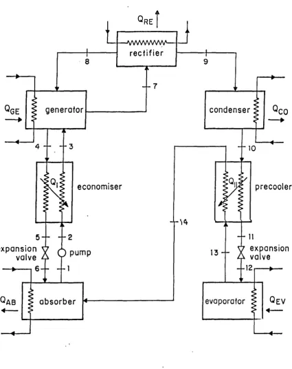
With reference to Figure 3.3, the mass and heat balances of the system using mass flow rates and enthalpies at different state points of the cycle can be expressed as follows:
(3.17)
(3.18)
(3.20)
(3.21)
(3.22)
QAB -Q+Q - QGE EV
CO
M4 mi mw
M
8 = M9 = M10 = MAB
M
10 = M5 + M1
M
8 M4 = M7
M
5 = M7 = M6
Equations (3.8) and (3.17) - (3.25) give
EV _ (114 - 113)
(3.23)
(3.24)
(3.25)
(3.26)
(COP) =
ECL Q
GE H1 + [(FR) - 11 H 5 - (FR) H10
(Q Q ) (H
4 - H3) (COP)
"=
AB
"' C n = I +111 + [(FR-1)] H (3.27)
5 -(FR) H10.] 'GE
and
(COP)EH = 1 (COP)ECL (3.28)
where (COP)
ECL and (COP) " are the enthalpy based coefficients of
AB (COP)
(COP) = AT 0
-GE 4- QEV
(3.29) 3.4 HEAT TRANSFORMERS
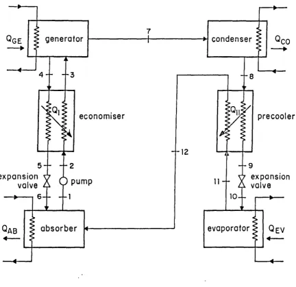
A heat transformer which is also called a reversed absorption heat pump is shown schematically in Figure 3.4 . Heat is added at a relatively low temperature T GE to the generator. The vapourized working fluid is condense( in the condenser at a temperature T c0 . The liquified working fluid leavii.q the condenser is pumped to a higher pressure region where it is evaporated by the input heat at a temperature T Ev . The evaporated working fluid is then absorbed in the absorber at a higher temperature T
AB' Thus an absorp-tion heat transformer has the unique capability of raising the temperature of a working fluid above that of the input heat.
There are three temperature levels in an absorption heat transformer when the same input heat is used at the evaporator and generator.
The coefficient of performance of an absorption heat transformer equal to the heat load in the absorber per unit of combined heat load in the generator and the evaporator
. It can be shown that the Carnot coefficient for an absorption heat trans-former shown in Figure 3.4 is
(COP)CT = .(1 T
CO ) (T AB ) T
GE TAB - TCO
Heat and mass balances can be used to theoretically derive an enthalpy based coefficient of performance for an absorption heat transformer
Q
AB H4+[(FR)-1] 115 (FR) H10 (COP)
ETQ
GE + QEV H1 +[(FR)-1] H5 - (FR) H10+ 114 - 11 3 .
3.5 WORKING FLUID PAIRS FOR ABSORPTION SYSTEMS 3.5.1 WORKING FLUID-ABSORBENT COMBINATIONS
The performance of an absorption system is critically dependent on the thermodynamic, physical and chemical properties of the working fluid and the absorbent. An extensive effort has been made in the evaluation of fluid combinations for absorption systems. [3.1 - 3.4].
3.5.2 PROPERTIES OF THE WORKING FLUID
Latent heat: The latent heat of vapourization of the working fluid should be as high as possible so that the mass flow rate of the working fluid within the system is reduced per unit of the heat delivered. This, in turn, will reduce the rate of circulation of the absorbent for a given change in concentration. [3.5].
Vapour pressure: The working fluid should give a reasonable pressure at the condensing temperature. Very low pressures cause inward leakage problems and cavitations in the pumps, whilst high pressures demand stronE containers and expensive pumps.
Critical point: The critical point should be high relative to the top cycle temperature.
3.5.3 PROPERTIES OF THE ABSORBENT
The absorbent should have a high boiling point and a negligible vapour pressure to avoid its transference into the condenser. The absorbents with large molecular weights or high polarity will be better for absorption systems. It is generally accepted that to avoid rectification, the differ-ence between the boiling points of the working fluid and absorbent should be greater than 200°C. The absorbent should have a high affinity towards the working fluid which is fundamental to the absorption process. Either solid or liquid absorbents can be used in absorption systems although the use of solid absorbents necessitates an intermittent cycle. A great many mineral and organic compounds simultaneously fulfil these criteria. The mineral salts such as halides and alkaline thiocyanates and organic com-pounds such as glycols and their derivatives are suitable absorbents.
Solubility: One of the conditions to be fulfilled by the mixture is the complete solubility of the absorbent in a working fluid, over a large rangc of concentrations, so that it will not crystallize during the operation. This implies that the crystallization point should be below the working temperature of the absorber and preferably below room temperature.
lower vapour pressures. This negative deviation from Raoult's law is very necessary for absorption cycles. Its importance lies in the fact that less solution is required to be circulated around the cycle for a given flow of the working fluid. Negative deviations from Raoult's law also result in a higher temperature lift between evaporator and absorber. Polar molecules generally exhibit negative deviations.
Enthalpy of mixing: The enthalpy of mixing or the heat of solution of an ideal solution is zero. The absorption working pairs, generally give a negative enthalpy of mixing. Solutions giving large negative deviations from Raoult's law, generally give high values for the enthalpy of mixing.
3.5.4 CRITERIA COMMON TO ALL FLUIDS
The other general requirements to be fulfilled by all the fluids (working fluid, absorbent and mixture) are as follows.
Chemical properties: All the fluids should be non-flammable, non-explosive non-toxic. They should be chemically stable in the operating range.
Fluids which are corrosive to the material of construction should be avoided, but in certain cases, corrosive chemicals which are thermodynam-ically attractive may be used with inhibitors. All the fluids must be readily available, cheap and compatible with materials of construction.
3.6 REFERENCES
3.1 R.M. Buffington, Qualitative requirements for absorbent-refriger-ant combinations, Refrigerating Engineering 57, 343-345, 384-386,
(1949).
3.2 W. Raldow, (Ed.), New working pairs for absorption processes,
Proceedings of a workshop in Berlin, Published by Swedish Building Research Association, Stockholm. Sweden, (1982).
3.3 W.J. Biermann, Candidate chemical systems for air cooled, solar powered absorption air conditioner design, Part II - Solid
absorbents, high latent heat refrigerants, unpublished report prepared for Department of Energy, Contract No. EG-77-C-03-1587, Carrier Corp., June (1978).
3.4 R.A. Macriss, T.S. Zawacki, Worldwide survey of absorption fluids data, IEA-HPC Newsletter, 6 (2), 25-28 June (1988).
-_
Q EVQco (COP) =
----•W
condenser
I I
evaporator Tco
tE v
PEV PCO
Pressure --f>
Pressure
Fig. 3.2 Absorption heat pump.
()An
co
Q 1' QM)
(COP)
gPmnrnIor
.11
nn•••
QEVII>
evaporator
QGE
Qc
o
TGETCO
TEV
evaporator
—8
QEV
TEV
II
4QAB
TAB
absorber
1
QGE
TGE
condenser
generator
10
economiser
9-1
E
low pressure
‘C7expansionzA
3—
valve
high pressure
9-1
expansion v
valve A
8—
-6
solution
pump
—7
evaporator
absorber
—2
pump
condenser
generator
10—
economiser
QEV
TEV
QAB
TAB
Qco
1-
co
QGE
TGE
Fig. 3.4 Simplified block diagram for a basic
NAB (FR) - m
AM
(4.1)
X
AB - XGE XAm - X
GE
(FR) = (4.2)
CHAPTER 4
THERMODYNAMIC DESIGN DATA FOR ABSORPTION HEAT PUMPS
4.1 INTRODUCTION
A conventional heat driven absorption heat pump basically consists of an evaporator, a condenser, a generator and an absorber as shown in Figure 4.1 The choice of the designer in the selection of the four basic opera-ting temperatures T
EV' TAB' TCO and TGE is limited by the Gibbs phase rule.
For an absorption system with two components and two phases, the number of degrees of freedom is two. If two of the operating variables are chosen as the free variables, then the other conditions are determined by the thermo-dynamic equilibrium data for the working pair.
The flow ratio (FR) is the ratio of the mass flow rate of solution to the mass flow rate of pure refrigerant in the primary circuit linking the con-denser and the evaporator [4.1]. This can be written for ammonia-water as
Alternatively, it can be rewritten in terms of concentrations as
where X
AB is the weight per cent of ammonia in the solution entering the generator from the absorber, and X
QEV (COP) =
ACL Q GE
(4.3)
and
and condenser rcspectively.
In this work, the data have been correlated using equations (1) and (2) for the ideal case of pure ammonia entering the condenser X = 1.0.
AM
Figure 4.2 illustrates the absorption cycle on an equilibrium chart for ammonia-water solutions. The points on the cycle correspond to the num-bered positions in Figure 4.1. Points 3, 5, 4 and 2 represent the solution cycle.
4.2 IDEAL COEFFICIENT OF PERFORMANCE OF AN ABSORPTION COOLING SYSTEM The coefficient of performance of an absorption cooling system is equal to the heat load in the evaporator per unit heat load in the generator
From thermodynamic, mass and heat balance considerations and referring to Figure 4.1, it can be shown [4.2] that
( T GE - TAB) ( T EV ) Q EV
(C°P)CCL
m(-TE" m TGE T CO - rEv
QEV (H1 - H8) (C ° P) ECL m Q
GE H6 + [ (FR) - Ii 114 - ( FR) H5
-(4.4)
(4.5)
where (COP)CCL is the Carnot coefficient of performance for the system and is dependen t only on the four basic temperatures T ail , TAB , T co and ToB.
(COP)
QGE QAB QCO (COP)
AH - (4.6)
QAB (COP) =
AT Q
GE + QEV
(4.10) 4.3 . IDEAL COEFFICIENT OF PERFORMANCE OF AN ABSORPTION HEATING SYSTEM The coefficient of performance of an absorption heat pump is equal to the 'heat load in the absorber and condenser per unit heat load in the generator
From thermodynamic mass and heat balance considerations and with reference to Figure 4.1, it can be shown that
(COP) ca = 1 + TGE - TAB
T Ey
(4.7)
) )
T
GE TGO - TEV
and
(COP) 11 = H
1 +[(FR)-1]1-14 -(FR)H5 + H6 - H8
(4.8) H
6 [ (FR) -1 J114- (FR) H5
where (COP)
CH is the Carnot coefficient of performance for the system and is dependent only on the four basic temperatures TE", TAB, and T ;
V rAB , GE
(COP) EH is the enthalpy based coefficient of performance for heating.
In the same way it can be shown that
QAB QCO
(COP) En = = 1 + (COP) ECL
QGE
(4.9)
(4.11)
(4.12)
(COP) =
ET 116 + [(FR) - 1] 11 4 - (FR)11 5 + H I - 118 (4.13) H
1 + [(FR) - 1] 114 - (FR)115
From thermodynamic, mass and heat balances considerations and with reference to Figure 4.3, it was shown [4.3 - 4.5] that
(T
EV - TCO)TAB (COP) =
CT (T
EV - TCO)TGE + AB - TGE)TEV
\
For T
EV = TGE equation (4.11)becomes
( T
AB )
(1 T CO ) (COP)
CT = TGE
AB - TCO
and
where (COP)
CT is the Carnot coefficient of performance for the system and is dependent on four basic temperatures T Ev , TAB, To and TGE , and (COP)ET is the enthalpy based coefficient of performance.
4.5 THERMODYNAMIC PROCESS DESIGN DATA FOR AMMONIA-WATER FOR COOLING The theoretical Carnot coefficient of perforpance
(COP)CCL' the enthalpy based coefficient of performance
(COP)ECL' the concentration of the solution in the absorber and the generator, and the flow ratio (FR) have been calcu-lated for the ammonia-water system for the following range of temperatures:
(1) evaporator temperatures T Ev from -30°C to 10°C in 5°C increments at absorber temperatures T
AB of 30, 40 and 50°C, and
(2) generator temperatures T
Equation (4.4) has been used for the calculation of the Gamut coefficient of performance. Equation (4.5) has been used for the calculation of the enthalpy based coefficient of performance. Equation (4.2) was used to cal-culate the flow ratio. The concentrations of ammonia in the absorber X
AB' and the generator X GE and the enthalpies at different state points were calculated using the thermodynamic data of Macriss et al [4.6]. Tables
(A1.1) list the design data for each combination of the four basic operating temperatures. (Appendix 1).
4.6 THERMODYNAMIC PROCESS DESIGN DATA FOR AMMONIA-WATER FOR HEATING The theoretical Carnot coefficient of performance (COP) GB , the enthalpy based coefficient of performance (COP)EH' the concentration of the solution in the absorber and generator and the flow ratio (FR) have been calculated for the ammonia-water system for the following ranges of temepraturesl
(1) evaporator temperatures T Ev from 20°C to 50°C in 10°C increments at absorber temperatures T AB from 50°C to 100°C in 10°C increments,
and
(2) generator temperatures T GE from 80°C to 200°C at condenser temperatures from 50°C to 70°C in 10°C increments.
Equation (4.7) has been used for the calculation of the Carnot coefficient of performance. Equation (4.8) has been used for the calculations of the enthalpy based coefficient of performance. Equation (4.2) was used to calculate the flow ratio. The concentrations of ammonia in the absorber X
4.7 THERMODYNAMIC PROCESS DESIGN DATA FOR AMMONIA-WATER FOR COOLING AND SIMULTANEOUS HEATING
The theoretical Carnot coefficient of performance (COP) CL , the enthalpy based coefficient of performance
(COP)ECL' the concentrations of the solu-tion in the absorber and generator, and the flow ratio (FR) have been cal-culated for the ammonia-water mixture for the following ranges of tempera-tures:
(1) evaporator temperatures T Ev from -10°C to 10°C in 5°C increments at absorber temperatures T AB from 50°C to 100°C in 10°C increments,
and
(2) generator temperatures T
GE from 80°C to 200°C at condenser temperatures T co from 50°C to 70°C in 10°C increments.
Equation (4.4) has been used for the calculation of the Carnot coefficient of performance. Equation (4.5) was used for the calculation of the
enthalpy based coefficient of performance. Equation (4.2) was used to calculate the flow ratio. The concentrations of ammonia in the absorber X
4.8 THERMODYNAMIC PROCESS DESIGN DATA FOR AMMONIA-LITHIUM NITRATE FOR COOLING
The thermodynamic design data have been calculated for the following ranges of temperatures:
( 1) evaporator temperatures T Ev from -30°C to 0°C in 5°C
Increments at absorber temperatures T AB of 30, 40 and 50°C, and
(2) generator temperatures T Ev from 65 to 145°C at 5°C increments at condenser temperatures T co from 30 to 50°C at 10°C
increments.
Tables (A1.4) list the design data for each combination of the four basic operating temperatures. (Appendix 1).
4.9 THERMODYNAMIC PROCESS DESIGN DATA FOR AMMONIA-LITHIUM NITRATE FOR HEATING
The thermodynamic design data have been calculated for the following ranges of temperatures:
(1) evaporator temperatures T Ev from 20 to 50°C in 10°C increments at absorber temperatures T
AB from 50 to 100°C in 10°C increments
and
(2) generator temperatures T oE from 90 to 170°C at condenser temperatures T co from 50 to 70°C in 10°C increments.
4.10 THERMODYNAMIC PROCESS DESIGN DATA FOR AMMONIA-LITHIUM NITRATE FOR COOLING AND SIMULTANEOUS HEATING
The thermodynamic design data have been calculated for the following ranges of temperatures:
(1) evaporator temperatures T Bv from -10°C to 15°C in 5°C at absorber temperatures T AB from 50°C to 100°C in 10°C increments,
and
(2) generator temperatures T GB from 90°C to 170°C in 10°C
increments at condenser temperatures T co from 50°C to 100°C in 10°C increments.
Tables (A1.6) list the design data for each combination of the four basic operating temperatures. (Appendix 1).
4.11 THERMODYNAMIC PROCESS DESIGN DATA FOR AMMONIA-WATER FOR HEAT TRANSFORMERS
The theoretical Carnot coefficient of performance (COP) a , and enthalpy based coefficient of performance (COP)ET' the concentrations of the
solution in the absorber and generator, and the flow ratio (FR) have been calculated for the ammonia-water system for the following ranges of temper-atures:
(1) evaporation temperatures T Bv from 30°C to 70°C in 10°C increments at absorber temperatures T AB from 40°C to 120°C in 10° increments,
and
temperatures T co from 10°C to 50°C in 10°C increments.
Equation (4.11) has been used for the calculation of the Carnot coefficient of performance. Equation (4.13) was used for the calculation of the
enthalpy based coefficient of performance. Equation (4.2) was used to calculate the flow ratio. The concentrations of ammonia in the absorber X
AB and the generator XGE and the enthalpies at different state points werE calculated using the thermodynamic data of Macriss et al [4.6]. Tables (A1.7) list the design data for each combination of the four basic operating temperatures. (Appendix 1).
4.12 THERMODYNAMIC PROCESS DESIGN DATA FOR AMMONIA-LITHIUM NITRATE FOR HEATTRANSFORMERS
The theoretical Carnot coefficient of performance (COP) n , and the enthalpy based coefficient of performance (COP)
ET the concentrations of the solution in the absorber and generator, and the flow ratio (FR) have been calculated for the ammonia-lithium nitrate system for the following ranges of tempera-tures:
(1) evaporation temperatures T Ev from 30 to 90°C in 5°C increments at absorber temperatures T
AB from 70 to 140°C in 10°C increments,
and
(2) generator temperatures T a, from 50 to 90°C in 5°C increments at condenser temperatures TCO from 10 to 50°C in 10°C
increments.
enthalpy based coefficient of performance. Equation (4.2) was used to calculate the flow ratio. The concentrations of ammonia in the absorber X
AB and the generator XGE and the enthalpies at different state points wer calculated using the thermodynamic data of Infante Ferreira [4.7].
Tables (A1.8) list the derived thermodynamic design data for each combination of the four basic operating temperatures. (Appendix 1).
4.13 DISCUSSION OF THERMODYNAMIC PROCESS DESIGN DATA
For the two working systems ammonia-water and ammonia-lithium nitrate the interactions of the operating temperatures have been illustrated graphi-cally in Figures (4.4 - 4.28) for different operating modes.
4.14 THE IMPORTANCE OF DERIVED THERMODYNAMIC DATA
In absorption systems, the coefficient of performance is a measure of the system efficiency. The flow ratio determines the size of the various item of equipment. An increase in the flow ratio affects the performance in thl following ways:
(i) the concentration difference between the absorber and generator is decreased,
(ii) the load on the economiser, normally placed between the absorber and generator is increased [4.8], [4.9],
(iii) the heat losses from the system could be higher, and
For the same value of the coefficient of performance, the flow ratio will be different from one working pair to another.
For working pairs for which the thermodynamic and thermophysical data are available, the correlation between the operating temperatures together wit the theoretical coefficients of performance and the flow ratios presented in this work will also help the process design engineer in the choice of items of equipment and their sizing, especially for the economiser heat exchanger. The data presented will provide information on the effect on efficiency due to changes in operating conditions and information on pos-sible combinations and operational limits of .temperatures for the ammonia-water and ammonia-lithium nitrate systems.
4.15 CONCLUSIONS
4.16 REFERENCES
4.1 M.A.R. Eisa, M.G. Sane, S. Devotta and F.A. Holland, Experimental studies to determine the optimum flow ratio in a water-lithium bromide absorption cooler for high absorber temperatures , Chem. Eng. Res. Des., 63 (4), 267-270 (1985).
4.2 M.A.R. Eisa, S. Devotta and F.A. Holland, Thermodynamic design data for absorption heat pump systems operating on water-lithium bromide, part 1: cooling, Applied Energy 24, 287-301 (1986).
4.3 M.A.R. Eisa, R. Best and F.A. Holland, Thermodynamic design data for absorption heat transformers, Part 1: Operating on water-lithium bromide, J. Heat Recovery Systems 6 (5), 421-432 (1986).
4.4 R.E. Siddig Mohammed, F.A. Watson and F.A. Holland, Study of the operating characteristics of a reversed absorption heat pump system (heat transformer), Chem. Eng. Res. Des. 61(6), 283-289 (1983).
4.5 M.A.R. Eisa, R. Best and F.A. Holland, Thermodynamic design data for absorption heat transformers, Part II: Operating on water-calcium chloride, J. Heat Recovery Systems 6(6), 443-450 (1986).
4.7 Infante Ferreira, Thermodynamic and physical property equations for ammonia-lithium nitrate and ammonia-sodium thiocyanate solu-tions, Solar Energy, 32 (2), 231--236 (1984).
4.8 I.E. Smith, C.O.B. Carey and C.F. Smith, Absorption heat pump research, Proceedings of a Workshop in Berlin. Published by Swedish Building Research Association, Stockholm Sweden, pp 149-151 (1982).
4.9 M.A.R. Eisa, S. Devotta and F.A. Holland, A study of the economiser performance in a water-lithium bromide absorption cooler, Int. J. Heat and Mass Transfer 28 (12), 2323-2329
absorber
condenser
generator
QGE
solution
pump
expansion valve
evaporator
Fig.4.1
Simplified
block diagram
for a basic absorption
solution pump
expansionZ valve
3
evaporator absorber
QAB
T -10°C
TCQ = 30°C
n
\
\
(PR) \sec\
\
\
\ \400c
N
50°C
4
0° 2.42.0
In In
0
1.6
g
0.80
0.58
2 p0.4
0
• 0.3
5
8 0.2
10.0
7.5
In
a)
In 0
.5
5.0
2.5
0.
1VN\-A-i:\--\25D c- -
n
.
I . I . I 1 180 1C0 120 140 160 180 200
. .
generator temperature 1 °C)C.)
Fig. 6.4 Plot of coefficients of performance and flow ratio against generator temperature at three different absorber temperatures
Pages 54-56