ISSN: 1992-8645 www.jatit.org E-ISSN: 1817-3195
3675
1JAAFAR A. ALDHAIBAINI, 2MOHANAD S. ALKHAZRAJI, 1,3NAEL A. AL-SHAREEFI
1,3Collage of Engineering, University of Information Technology and Communications (UOITC) Baghdad, Iraq
2Electrical and Electronic Engineering Department, University of Technology (UOT) Baghdad, Iraq
3Computer Techniques Engineering Department, Dijlah University Collage, Baghdad, Iraq E-mail: 1[email protected]
ABSTRACT
For several users' existence, there are much internal or external interference such as inter-symbol interference (ISI) obstacles act during multiple paths reception technique for receiving data at high data rates in "ultra wideband (UWB) technology". For these several reasons, UWB wireless rake receiver technique was designed to combine many received resolvable paths, normally greater than 100 paths. Structures of rake receiver implementation in literature review have been structured, proposed, and designed towards increasing the system complexity. These designs were done to get better performances through outdoor or indoor reception of multi-path propagation to reduce the probability of bit error (Pe) or bit error rate (BER). So, many rake receivers have been designed in the last publications to decrease the number of resolvable paths that must be estimating and combining by combiner. To achieve this main goal, we proposed two structures of combiner in the rake receiver, Signal Separation Maximal Ratio Combiner Partial Rake (SS-MRC-PR) receiver and Signal Separation Maximal Ratio Combiner Selective Rake (SS-MRC-SR) receiver. These proposed combiners are based on separation of received signals depending on their signs to make comparison between the number of negative signs and positive signs. The previous receivers were produced to reduce the system complexity with fewer correlators and to improve the system performance with very low Pe at increased signal-to-noise ratio (S/N). Before the decision circuit, a comparator is used to make comparison between two quantities, negative quantity and positive quantity to decide whether the wireless transmitted bit is 0 or 1. The Pe was simulated by "MATLAB simulation software" for wireless multi-path environments of "impulse radio time-hopping binary phase shift keying (TH-BPSK) modulation" and the simulation results were obtained and compared with those of "Conventional Maximal Ratio Combiner Partial Rake (C-MRC-PR)" receiver and "Maximal Ratio Combiner Selective Rake (C-MRC-SR)" receiver. This comparison show the reducing of Pe against S/N for the proposed receivers compared to that for conventional receivers which supports the proposed designs.
Keywords: Rake Receiver Structures, SS-MRC-PR and SS-MRC-SR, Sign Separation of Signals,
Conventional MRC, Pe and BER
1. INTRODUCTION
Rake processing of ultra wideband (UWB) signals through indoor and outdoor multi-path propagation has the ability to collect the energy of diverse, multi-path copies. For this reason, the rake receiver technique is an important innovated device to maximize the reception gain in communication system and to enhance the performance of UWB communication systems in wireless channels. In the presence of multi-user interference (MUI) and inter-symbol
interference (ISI), cause during transmission, the performance sometimes weak. The MRC (maximal ratio combiner) technique is used in rake receive to "maximize the signal-to-noise ratio (S/N)" [1]. The most serious obstacle is ISI that must be mitigated along the transmission data especially at high data rate during indoor reception or transmission.
The ISI mitigation leads to reduce effects of multi-user interference (MUI) so most of researches are focused on minimizing MUI for
3676 several users. Rake receiver technique was found to enhance the capability of consumption the received energy for multiple paths. Since the UWB frequency range is 7.5 GHz depending on the "Federal Communications Commission (FCC)" [2], "multi-path components (MPCs)" are resolving to support the ability for extracting "individual multipath signals" by rake receivers. In the rake receiver, there are three schemes to combine direct and indirect multiple resolved paths.
These schemes are "all-rake (A-rake), partial-rake (P-rake), and selective-rake (S-rake)". The optimal one is A-rake receiver that combines all strong and weak MPCs, so it is complicated because of more than one hundred correlators must be used. The S-rake receiver combines strongest paths (Ls) which are selected from several clusters in each ary. The main process of P-rake receiver is to collect first arrived resolved MPCs at limited time as a partial paths (Lp paths) in each correlation as shown in [3, 4] with twenty correlators. The S-rake receiver was developed to enhance the system performance of indoor wireless detection "in the presence of MUI based on the mitigation of additive white Gaussian noise (AWGN) disturbance" [5] and supported by adding "interference-sensing (IS)" device to this system for increasing the sensitivity as presented in [6].
The optimal scheme for combining of incident MPCs can be done by A-rake that combines nearly all incident resolvable baths so is is more complicated to apply in indoor systems. However the system cost and size are increased to produce hardware structure and nowadays, they are the main factors in fabrication by many companies. One of the improvements work as it was done by [7] is to use quantity summation through non line of side (NLOS) indoor channel model (CM3).
In addition, to cross over the indoor obstacles, P-rake and S-rake receivers were produced to minimize the system complexity and combining less MPCs that incident on wireless antennas. In P-rake and S-rake receivers, still there are many weak or unnecessarily MPCs are combined and take more processing time so we need to reduce this time by minimizing number of correlators. To decrease the number of used correlators and limit the resolvable MPCs, signal separation in
MRC of SR and PR receivers was suggested in this paper.
Therefore, the required goal of this work is to decrease the probability of received bit errors (Pe) which leads decrease the system cost of the system and to minimize the size of wireless receiver by reducing the number of correlators by using commercially integrated circuits as in [8]. This work shows the simulation results of SR and PR receivers through indoor wireless channel that is passing propagating signals.
These results were processed and taken for receivers of 10 correlators and combining 4, 6, and 8 indoor paths. However the provided simulation results have a direct relationship between resolved and captured MPCs and the number of users. In addition, this paper presents enhanced results of the proposed SS-MRC-PR and SS-MRC-SR receivers using maximal ratio combiner to combine the separated signals depend on signals signs. The previous simulation results were performed or improved with four correlators and 8 or 6 or 4 incident combining paths.
The reminder of this research is organized as follows sections: Section 2 presents UWB generated signals and spread spectrum technique. Section 3 shows the indoor wireless channel model (CM1) that was used in simulation process. Section 4 derives the proposed rake receiver structures and the algorithms analysis. Section 5 gives an assessment of the simulated results and discusses at the required parameters of the channel model in partial and selective rake receivers. Section 6 shows the conclusion of this paper.
2. SYSTEM TRANSMISSION MODEL
ISSN: 1992-8645 www.jatit.org E-ISSN: 1817-3195
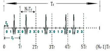
3677 period (Ts). The repeatedly transmitted data bits are propagated along many frames (Ns) and each frame is subdivided in to 4 chip slots of Tc duration length with one slot carrying the user’s transmitted data pulse. In analysis purposes, the energy of the signaling pulse p(t) was suggested to be unity, as P t dt 1 and to determine symbol duration by Ts = (Ns-1)Tf. The frame duration Tf was much greater than the Tc (chip duration) and the Tp (pulse duration) to avoid interferences or collisions [9].
[image:3.612.98.280.244.329.2]
Figure 1. Time hopping UWB spread spectrum of signal.
We considered a approach such as "binary phase shift keying BPSK modulation" in the transmitter of bipolar signaling form. In BPSK modulation, negative polarity represents bit 0 and positive polarity represents bit 1. "The advantage of using the BPSK scheme is to remove the discrete spectral lines in the power spectral density (PSD) and produces a zero mean when the polarity is changing" [10]. The information data is randomly generated by binary source generator in order to be spread and transmitted with a symbol rate of 1/Ts bits/sec. Transmitted pulse shaping power is expressed by PTx(t) of pulse duration Tp (0.167 ns), and the pulse shaping power is expressed as a 2nd derivative of "exponential Gaussian function" e / which is as follow:
where τ defines time-scaling factor or shape factor, and the form of transmitted signal is:
S t ∑ C P t jT (2)
C X w (3)
where Cj = spreading code and it is used to design spreading vector of xm (-∞ < m < ∞) and wn is the pseudorandom noise (PN) sequence with n up to the Nc block of the BPSK pulses (n = 0, 1, 2, …., Nc-1). "The TH-BPSK-UWB transmitted signal format for different users" is expressed as:
S t E ∑ X ∑ W P t mT
n T τ (4)
where Su(t) = transmitted signal for user u, τu o = reference delay related to u-th user that caused synchronous operation (0 ≤ τu
o ≤ Tf), and nuͼ [0, 1, …..Nc-1] which is used to include many users up to chip number of (Nc-1).
3. MULTI-PATH CHANNEL MODEL
The Transmitted S(t) signal cross multipath indoor channel of many obstacles which is based on "modified Saleh-Valenzuela (S-V) channel models" [11] for wireless indoor multi-path radiation as represented in Fig. 2 that was reported by IEEE 802.15.3a. These propagated signals were supposed to be incident and received by printed microstrip patch antenna [12].
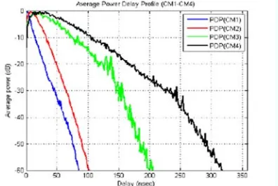
The proposed channel model by IEEE 802.15, 3a independent on observing the clustering phenomenon in many realizations of channel measurements. So that, we need to concentrate on UWB channel model technique which was derived from the original S-V model with modern slight modifications. In this work, log-normal distribution was supposed to be used rather than another distribution such as Rayleigh distribution for magnitude of multipath gain.
The used distribution seems better to fit the measured data. The independent fading through indoor channel was proposed for each lth cluster as well as for each kth ray within several clusters. The "power decay profile (PDP)" over 100 repetitions of the "IEEE CM1 channel model was generated in IEEE P802.15-02/490r1-SG3a" as shown in Fig. 3. These profiles indicated there is short fading time for LOS channel of indoor wireless paths. Therefore, the multi-path model consisted of the following parameters as presented in Table I and the "continuous-time channel impulse response" of the S-V model is represented in [13] and derived to be expresed by the following mathematical relationship:
h t X ∑ ∑ α , exp ,δ t T τ , (5)
3678 is 1 at θ ≠ 0. An expjθk,l equals to 1 for synchronization requirement between receiver and transmitter and the "discrete time impulse response of the modified S-V model" can be written as [14]:
h t X ∑ ∑ α , δ t T τ , (6)
where αi
k,l denote multi-path gain coefficients of the kth ray within the lth cluster, Til = delay of lth cluster, τi
k,l = delay of the kth multi-path component relative to the lth cluster arrival time (Til), X
[image:4.612.96.290.302.529.2]i defines value of random variable that represents the log-normal fading of the total multi-path, L = observed clusters number, and i refers to the ith realization of the channel model.
Table 1. Indoor channel model parameters
Channel parameters values
Cluster arrival rate (ns-1) 0.0233
Ray arrival rate (ns-1) 2.5
Cluster decay factor (ns) 7.1
Ray decay factor (ns) 4.3
standard deviation of cluster’s
lognormal fading term σ1 (dB)
3.3941
standard deviation of ray’s
log-normal fading term σ2 (dB)
3.3941
standard deviation of the
log-normal shadowing term σx (dB)
3
Figure 2. Three clusters in a ray as characteristics of exponential power decay in S-V channel model.
P T /T exp (T T when
l 0 (7)
P τ ,/τ , =exp τ , τ ,
when k 0 (8)
The impulse channel coefficients can be expressed as follows:
α , P,ϑ β , (9)
where pk,l defines the random variables of equi-probable (1) values, ϑ1 = fading of lth cluster, and
βk,l = log-normal channel coefficients and they are characterized by the following expression:
20 , ∝ ,, (10)
where N = normal notation and µk,l = variable of power decay. Therefore n1 N(0 , σ21) and n2 N(0 , σ22) are correspond to the independent fading on each cluster and ray, respectively.
│ ,│ Ω ,/ (11)
where Tl = excess delay, Ω0 = mean energy of the 1st path and 1st cluster (equal to < |α0,0|2 >), and pk,l = equi-probable 1. "Then the power decay variable (k,l) for the amplitude of each cluster and each multi-path ray within the cluster" can be determined by:
,
Ω τ ,/γ
(12)
[image:4.612.100.288.307.437.2]Since the "log-normal shadowing of the total multi-path energy" is expressed and captured by the term Xi. The contained total energy in the terms of (αik,l) is normalized to unity for each use and the power delay profile (PDF) is shown in Fig. 3 for four indoor channel models at different ranges in case of LOS and NLOS. PDF is shadowing at time depends on type of channel model which are CM1, CM2, CM3, and CM4.
Figure 3. Profile of average power decay for indoor propagation through channel models at different ranges.
[image:4.612.322.520.471.604.2]ISSN: 1992-8645 www.jatit.org E-ISSN: 1817-3195
3679 general expression for user u at the input surface of the receiving printed antenna.
∑∞ ∑ ∑ ∑ ,
∞
, (13)
Let us consider high efficiency and high gain printed microstrip patch antenna at the reception system for wireless UWB technology applications as proposed and shown in [16]. The considered omni-directional antenna is "spade-shaped microstrip patch antenna" with low return losses (less than -10 dB) at the output of receiving antenna (RRx) and the input of the transmitting antenna (RTx). The Friis transmission formula (14) shows the relationship between and the output power of the receiving antenna (PRx) and the input power of the transmission antenna (PTx) when used antennas are separated by wireless distance d [16].
(1-│ │ ) 1
| || |│ . │ (14)
where GRx = gain of the reception antenna, GTx = gain of the transmission antenna, λ = wavelength, and │ │ defines as the polarization matching factor between the previous antennas. The reception printed antenna gain enhances the total "multi-path gain in channel impulse response".
4. THE PROPOSED RAKE RECEIVER
The pulse distortion by antennas and channels affect on original shape of the pulse that is received by wireless receiver and will be little bit different from the transmitted pulse [17]. After that, the "white Gaussian noise (n(t))" is corrupting the required UWB signals of L copy correlators received by each user (ru(t)). this signal is received and driven by ru(t)=h
i(t)su(t)+n(t), where term n(t) is the noise including AWGN component and interference sources. The sign denotes convolution between transmitted signals and impulse channel response coefficients.
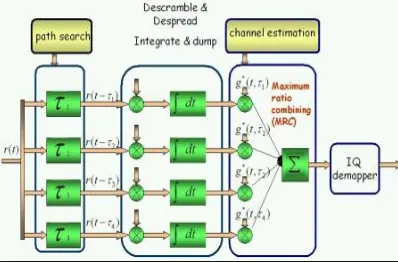
To run simulation process in rake receiver, local template multiple pulses (g0, g1, g2,….g(L-1)) are generated by pulse-match filter or symbol-match filter with delay times between these pulses which depend on time-hopping code. In most of rake receiver structures, the template pulses are
estimated locally depending on the received signals by doing so blindly or transmitting some training sequences. The received signals should be multiplied with the template pulses and pass to integrators for applying correlation process or to make correlation with desired signals [18].
In reception side, each correlator behaves as a "matched filter" to optimize the main ability to reduce or suppress most of the received or internal noise by limited filter gate [19]. Fig. 4 shows matched filter operates as autocorrelation receiver that includes an integrator and multiplier to correlate multiple path pulses. The RF signals are integrated in integrators to yield DC voltage signals along the pulse duration which is less than one nanosecond. At detection process, the template signals are matched exactly in shape and time with incoming signals. Note that in rake reception, each implementation of rake structure is using parallel correlators (branches) and outputs of these branches are combined by combiner subsystem. The output of each branch is decomposed into required matched filter output signal (ro(t)) and matched filter output noise signal (no(t)) due to input noise and The output signal from each correlator [ru s(t) = ruo(t) + no(t)] is sampled with sampling frequency of 100 GHz based on Nyquist sampling theorem and multiplied by MRC weights vector.
[image:5.612.321.516.487.587.2]These weights are supported by channel estimation of the direction and pulse shape at each multi-path delay.
Figure 4. Improving S/N by MRC in time domain scenario.
r t r t g t τ dτ (15)
n t n t g t τ dτ (16)
3680 Perfect channel estimation was proposed between receiver and transmitter and to simplify the process, optimal reception can be used. The MRC combination technique is used to get least Pe after phase rotation correction. The several phase directions are generated by indoor fading wireless channels and also they are summing chips of the current symbols. The block diagram is shown in Fig. 5 for the proposed design of rake receiver with received signal by MRC which is mixing between noise signals and desired signal. Therefore, the proposed structures are SS-MRC-PR and SS-MRC-SR receivers to combine the output of all branches.
[image:6.612.92.291.382.513.2]In the combiner, there are sign decision elements with the same number of branches to decide whether the output pulse amplitude negative or positive (Ap). "If the amplitude of the pulse is positive, the pulse will be passed to the positive summation circuit, and if it is negative the pulse will be passed to the negative summation circuit".
Fig. 5. Block diagram of MRC rake receiver structure.
The received signal by sign detector (qs) is consisting of noise and desired signals which are causing errors in detection of required signals and can be derived as:
q t A t n t when (s = 0, 1, 2,…L-1) (17)
"where +Ap is the amplitude of the positive pulse that corresponds to bit 1, and –Ap is the amplitude of the negative pulse that corresponds to bit 0. From the output of all fingers, the digit will be detected as 1 if the values of the sample pulses are positive, and the digit will be detected as 0 if the values of the sample pulses are negative. Because of noise, not all of the samples from fingers used are positive for bit 1 or negative for bit 0. From the general situation in a conventional rake receiver and zero
detection thresholds, the probability of receiving an error bit is less than half of multi-path components that are processed, thus, we suggested that the number of error samples be less than 50% of all of the samples from the fingers.
After that, the positive samples {qp(t)} are passed to the positive summation element and the negative samples {qn(t)}are passed to the negative summation element".
q t A t n t For (p= 0, 1, 2, ……P) (18)
q t A t n t For (n= 0, 1, 2, ……N) (19)
where N = number of negative quantities and P = number of positive quantities. These values can be collected separately to introduce peak amplitudes represented by positive peak amplitude function (B(t)) and negative peak amplitude function (C(t)) which are represented as below:
B t ∑ q t τ (20)
C t ∑ q t τ (21)
Thus, B(t) defines the collection of positive quantities for the main pulse and its copies received from multi-path and processed by several fingers when the transmitted bit is 1. In addition, B (t) defines the error pulses when the transmitted bit is 0. C (t) defines the collection of negative quantities of received pulses from multi-path propagation when the transmitted bit is 0, and it also defines the error pulses when the transmitted bit is 1.
After converting the values from analog to digital format (B(t) and C(t)) can be passed to the comparator of two outputs, one gives bit 1 when B(t) ≥ C(t) and the other gives bit 1 when B(t) < C(t). The outputs of the comparator are expressed by Vop and Von, as shown in Table 2; the mean positive value (Vop) is associated with bit 1, and the mean negative value (Von) is associated with bit 0. After that both quantities are supplied to the decision circuit, which determines whether the expression for each quantity is bit 1 or bit 0.
Table 2. Comparator output characteristics
Comparator output Vop Von
B(t) ≥ C(t) 1 0
ISSN: 1992-8645 www.jatit.org E-ISSN: 1817-3195
3681 Since the normal rake receiver is used to capture most of the multi-path energy pulses, a decision element is used with zero thresholds, and it must be set to determine the value of bˆ. If the energy that is received is greater than the threshold energy, the bit decision is 1; otherwise, it is 0. The decision is used at the maximum amplitudes of the signal and the noise at t = tm. Hence, the signals that are received by the threshold device are Vop(tm) and Von(tm) and they are defined as:
V t B t n t (22)
V t C t n t (23)
Then, the optimum threshold detection is function of output positive value decision with dec{Vop(tm)} = 1 if Vop(tm) ≥ 0 and function of output negative value decision with dec{Von(tm)} = 0 if Von(tm) < 0. In particular, the bit error probability (Pe) is a direct quality measure used to make evaluation for the performance of the wireless communication system. The Pe can be measured depending on the Q function and the S/N, which is directly related to the bit energy (Eb) and simulation noise energy (N0), whoever, Pe is [20, 21]:
Pe Q S/N Q (24)
5. SIMULATION RESULTS AND
DISCUSSIONS
The simulation results are run through indoor wireless LOS multi-path channel model (CM1) with discovering range up to four meters. The standard indoor parameters for CM1 were taken from Table 1 of IEEE 802.15.3a final report. The proposed and conventional SR and PR receivers were processed or simulated by using "MATLAB simulation software" for determination of the strongest paths and the first arriving paths as an advantage of capturing these paths. Randomly, 80,000 bits were generated and spread to be transmitted over wireless indoor channel. The pulse shaping factor was 0.220 ns with Ns = 5 pulses for each bit for each pulse duration of 0.2 ns through 0.5 ns chip time, and BPSK digital modulation technique was taken for transmitted bits.
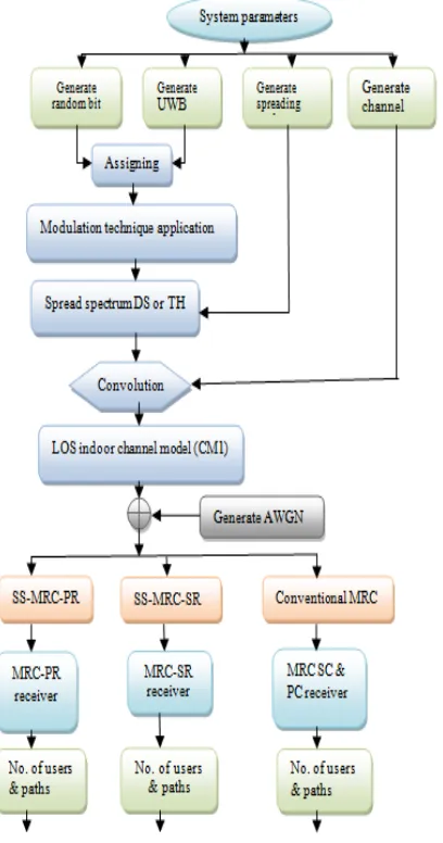
Many simulation runs were processed to determine the mean value of Pe over 50 direct and indirect channels at varying S/N from 0 to 20 dB. These runs were confirmed to show the performance the proposed rake receiver structures in wireless communication systems. The simulation processing steps are represented in Fig. 6 as flowchart diagram for the "proposed rake receiver" to show the software transient. The results of Pe verses S/N were obtained in Fig. 7 to clear the performance evaluation of the designed SS-MRC-PR receiver and C-MRC-SS-MRC-PR with two users and several partial multi-path components (Lp) such as eight, six, and four correlators. These curves are compared with C-MRC-PR results at same number of Lp through CM1 multi-path channel model. The comparison of the proposed and conventional rake structures were taken when the S/N value was 10 dB at same condition of CM1 channel. The Pe was reduced from 0.220 to 0.0054 with four correlators and from 0.175 to 0.0013 with eight correlators. At the same parameters of CM1, the Pe characteristics of the proposed SS-MRC-SR receiver are shown in Fig. 8.
These characteristics can be confirmed as interesting results for Pe when comparing with those of the C-MRC-SR. At 10 dB S/N, the Pe was reduced from 0.170 to 0.0014 at four correlators, from 0.160 to 0.00043 at six correlators, and from 0.150 to 0.00021 at eight correlators (4, 6, & 8 selective paths). After that, the MATLAB software was simulated again for both conventional and proposed rake receivers to obtain the system performance of the proposed receiver structures.
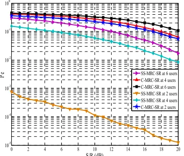
The changing parameter is the number of users at Lp = 10 (multi-path partial components) and Ls = 10 (multi-path selective components) at same conditions of CM1 channel model. In comparison with C-MRC-PR receiver and at 10 dB of S/N, Fig. 9 shows the Pe versus S/N for SS-MRC-PR receiver in CM1 channel model. The Pe is reduced from 0.350 to 0.160 at 6 users, from 0.290 to 0.095 at 4 users, and from 0.260 to 0.00055 at 2 users. The system performances of the proposed SS-MRC-SR receiver are illustrated in Fig. 10 at 10 strongest arrived paths with 2, 4, and 6 users were combined.
TH-3682 UWB system performances are degraded because it has better Pe performance in overall S/N range. This performance is improved because the received combining powers is maximized by collecting energy from correlators and reducing the multi-path interference or inter symbol interference. From these simulated figures, the advantage of reducing Pe can be concluded that the SS-MRC-PR receiver and the SS-MRC-SR receiver have enhanced the wireless indoor communication system with a greater number of partial paths (Lp) and selective paths (Ls). This advantage leads to better system performance with application of different numbers of indoor users. Results conclusions are briefed in Table 3 as a comparison between the proposed rake receivers and conventional rake receivers for reducing the probability of bit error when the S/N is 14 dB.
[image:8.612.150.518.317.697.2]Figure 6: Flowchart Diagram For The Proposed Signal Separation Rake Receiver.
Figure 7. Pe Reducing With S/R Of The Partial Rake (PR) Receiver With Two Users.
Table 3. Pe Reducing Values At Varying Number Of Paths And Users.
Figure 8 The Pe Reducing S/R Of The Selective Rake (SR) Receiver For Two Users.
0 2 4 6 8 10 12 14 16 18 20
10-4 10-3 10-2 10-1 100
S/R (dB)
P
e
C-MRC-PR at Lp=4 C-MRC-PR at Lp=6 C-MRC-PR at Lp=8 SS-MRC-PR at Lp=4 SS-MRC-PR at Lp=6 SS-MRC-PR at Lp=8
0 2 4 6 8 10 12 14 16 18 20
10-5 10-4 10-3 10-2 10-1 100
S/R (dB)
Pe
C-MRC-SR at Ls=4 C-MRC-SR at Ls=6 C-MRC-SR at Ls=8 SS-MRC-SR at Ls=4 SS-MRC-SR at Ls=6 SS-MRC-SR at Ls=8
Rake Receiver Path's
number
Pe at 2
users users number(u) Pe at 8 fingers
C_MRC-PR LP = 4 0.150 2 0.170
LP = 6 0.120 4 0.21
LP = 8 0.10 6 0.280
SS-MRC-PR Lp = 4 0.0047 2 0.00018
LP = 6 0.0013 4 0.044
LP = 8 0.00053 6 0.075
C-MRC-SR LS = 4 0.090 2 0.170
LS = 6 0.075 4 0.19
LS = 8 0.710 6 0.250
SS-MRC-SR LS = 4 0.00095 2 0.000026
LS = 6 0.00029 4 0.075
[image:8.612.313.525.319.664.2] [image:8.612.314.528.321.481.2]ISSN: 1992-8645 www.jatit.org E-ISSN: 1817-3195
[image:9.612.119.526.44.261.2]3683
Figure 9. The Pe Reducing With S/R Of The Partial Rake (PR) Receiver At Lp=8.
Figure 10. The Pe Reducing With SNR Of The Selective Rake (SR) Receiver At Ls=8.
Also we compared the simulation results of the proposed system with those obtained by A. P. Doukeli in [12] using "adaptive selective rake and adaptive partial rake" (AS-rake and AP-rake) receivers. The bit error probability (BEP) behavior results of AP-rake and AS-rake receivers are represented in Figure 11.
These simulation results of BEP or Pe against bit energy to noise power ratio (Eb/N0 or S/R) were chosen to know the system performance gain of the proposed wireless rake receivers. The adaptive rake receiver was run at LOS channel model (CM1) and the BEP was between 0.350 and 0.450 when the value of S/N was 40 dB during one user. However, in the working separation rake receiver, the Pe was between 0.30 and 0.0008 at 0dB S/R for different number of paths and users used by the partial-rake receiver and selective-rake receiver.
Figure 11. Bit Error Probability (Pe) Versus SNR With Different Numbers Of Combined Fingers For CM1
Channel Model [9].
6. CONCLUSION
In this work, we proposed signal separation combiner using MRC technique that is combining multi-path received from rake receiver of several correlators for TH-UWB indoor wireless systems. These combiners for UWB propagation are SS-MRC-PR receiver and SS-MRC-SR receiver. After analysis, the systems were "simulated using MATLAB simulation software" to show the required system performance by reducing the Pe compared with increasing S/N. The simulation results of the proposed combiners were compared with those used in conventional and [12] rake receivers. Results show the enhanced performance of the system using SS-MRC-SR and SS-MRPR combiners rather than those using C-MRC-SR and C-MRC-PR combiners. In addition, these results were compared with those obtained by ref. [12] with high complexity through the conditions of indoor CM1 channel model.
REFRENCES:
[1] J. G. Prokis, ‘‘Digital Communications, 4th Edition,’’ McGraw-Hill International Press, 2001, pp. 795-806.
[2] A. F. Molisch, J. R. Foerster, and M. Pendergrass, ‘‘Channel Models for Ultra Wideband Personal Area Network,’’ IEEE Wireless Commun., Vol. 10, pp. 14-21, Dec. 2003.
[3] E. Zochmann et al., "Directional Evaluation of Receive Power, Rician K-Factor and RMS Delay Spread Obtained from Power Measurments of 60 GHz Indoor Channels," in
0 2 4 6 8 10 12 14 16 18 20
10-5 10-4 10-3 10-2 10-1 100
S/R (dB)
Pe
SS-MRC-PR at 6 users C-MRC-PR at 4 users C-MRC-PR at 6 users SS-MRC-PR at 2 users SS-MRC-PR at 4 users C-MRC-PR at 6 users
0 2 4 6 8 10 12 14 16 18 20
10-5 10-4 10-3 10-2 10-1 100
S/R (dB)
Pe SS-MRC-SR at 6 usersC-MRC-SR at 4 users
[image:9.612.96.284.287.446.2]3684 2016 IEEE-APS Topical Conference on Antennas and Propagation in Wirless Communications (APWC)2016 IEEE-APS Topical Conference on Antennas and Propagation in Wireless Communication, pp. 246-249, 2016.
[4] F. Craciun, I. Marghescu, and O. Fratu, ‘‘Rake Receiver Performances for PAM-TH-UWB Systems,’’ 19th Telecomunications Forum TELFOR Conference, Belgrade, Serbia, pp. 22-24, Nov. 2011.
[5] N. C. Beaulieu, and D. J. Young, “Designing time-hopping ultra wide bandwidth receivers for multiuser interference environments,” Proc. IEEE, Vol. 97, no. 2, pp. 255–284, Feb. 2009.
[6] D. J. Young, and N. C. Beaulieu, “Time-hopped ultra-wide bandwidth receiver designs using multiuser interference sensing,” in 2011 IEEE Int. Conf. Ultra-Wideband (ICUWB), pp. 34– 38, Sep. 2011.
[7] Rashid A. Fayadh, F. Malek, Hilal A. Fadhil, and Norshafinash Saudin, ‘‘Improved Rake Receiver Based on the Signal Sign Separation in Maximal Ratio Combining Technique for Ultra Wideband Wireless Communication Systems,’’ World Academy of Science, Engineering and Technology, International Journal of Electrical, Robotics, Electronics and Communications Engineering, Vol:7 No:12, 2013.
[8] H. S. Ryu, J. S. Lee, and C. G. Kaug, ‘‘BER Analysis of Dual-Carrier Modulation (DCM) over Nakagami-m Fading Channel,’’ IEICE Trans. Commun, vol. E94-B, no.7, pp. 2123-2126, July. 2011.
[9] D. Cassioli, M. Z. Win, F. Vatalaro, and A. F. Molisch, ‘‘Low Complexity Rake Receivers in Ultra-Wideband Channels,’’ IEEE Transactions Wireless Communications, Vol. 6, pp. 1265-1275, 2007.
[10] L. B. Agudelo and A. N. Cadavid, ‘‘A Novel Correlation Adaptive Receiver for High Speed Transactions in Ultra Wide Band Systems with Realistic Channel Estimation,’’ IEEE Journal on Selected Area in Communications, Vol. 27, No. 8, Oct. 2009.
[11] A. A. Saleh, and R. A. Valenzuela, ‘‘A Statistical Model for Indoor Multipath Propagation,’’ IEEE Journal of Selection Areas Communication, Vol. 5, pp. 128-137, 1987. [12] Z. Xiao, L. Su, D. Jim, and L. Zeng,
‘‘Performance Comparison of RAKE Receivers in SC-UWB Systems and DS-UWB
Systems,’’ IEICE Trans. Commun, vol. E93-B, no.4, pp. 1041-1044, April. 2010.
[13] A. P. Doukeli, A. S. Lioumpas, G. K. Karagiannidis, and P. V. Frangos, ‘‘Increasing the Efficiency of Rake Receivers for Ultra-Wideband Applications,’’ Springer Science + Business Media, Wireless Pers. Commun., Vol. 62, pp. 715-728, July 2012.
[14]J. Foerster, ‘‘Channel Modeling Sub-committee Final Report,’’ Intel R&D, Wireless Area Network, IEEE P802.15.02/490r1-SG3a, August 2012.
[15] Guo N., Qiu R. C., Improved Autocorrelation Demodulation Receivers Based on Multiple-Symbol Detection for UWB Communications, IEEE Transaction Wireless Communication, Vol. 5 (8), pp. 2026-3031, 2006.
[16] R. A. Fayadh, F. Malek, H. A. Fadhil, ‘‘Spade-Shaped Patch Antenna for Ultra Wideband Wireless Communication Systems,’’ International Journal of Advanced Computer Research, Volume-3, Number-3, Issue-12 September-2013.
[17] M. R. Adeniz et al., ‘‘Millimeter Wave Channel Modeling and Cellular Capacity Evaluation,’’ IEEE Journal on Selected Areas of Communication, Vol. 32, No. 6, pp. 1164-1189, June 2014.
[18] M. Yoon, C. Lee, ‘‘An Important TR Prefilter for SSR Maximization in Indoor Wireless Communication System,’’ Wireless PERS Communication, Vol. 90(3), pp. 1519-1532, 2016.
[19] F. Han, and K. R. Liu, ‘‘A Multiuser TRDMA Uplink System with 2D Parallel Interference
Cancelation,’’ IEEE
TransactionsCommunication, Vol. 62 (3), pp. 1011-1022, 2014.
[20] B. P. Lathi, & Z. Ding, ‘‘Modern Digital and Analogue Communication Systems. International Fourth Edition,’’ Oxford University Press, UK, pp. 506-715, 2010. [21] Rashid A. Fayadh, F. Malek, and Hilal A.