Surface Modification of NaCl Particles with Metal Films
Using the Polygonal Barrel-Sputtering Method
Satoshi Akamaru, Mitsuhiro Inoue, Takayuki Abe*
Hydrogen Isotope Research Center, University of Toyama, Toyama, Japan. Email: *[email protected]
Received May 22nd, 2013; revised June 21st, 2013; accepted July 3rd, 2013
Copyright © 2013 Satoshi Akamaru et al. This is an open access article distributed under the Creative Commons Attribution License, which permits unrestricted use, distribution, and reproduction in any medium, provided the original work is properly cited.
ABSTRACT
In this study, the surfaces of NaCl particles were modified with metal films using the polygonal barrel-sputtering me- thod. When Pt was sputtered on NaCl particles, the individual particles changed from white to metallic. Characteriza- tion of the treated samples indicated that thin Pt metal films were uniformly deposited on the NaCl particles. Immer- sion of the treated NaCl particles in water revealed that they floated to the surface of the water with the increase in the immersion time, although their original cubic shapes remained unchanged. The floating phenomenon of the Pt-coated NaCl particles, as mentioned above, suggests that NaCl was dissolved by the permeation of water through invisible de- fects such as grain boundaries in the Pt films, leading to the formation of hollow particle-like materials. It should be noted that uniform film deposition on the NaCl particles could also be achieved by sputtering with Au or Cu. Based on the obtained results, our sputtering method allows uniform surface modification of water-soluble and water-reactive powders that cannot be treated by conventional wet process using water.
Keywords: Particle Surface Modification; Ionic Crystal; Dry Process; Sputtering Technique; NaCl
1. Introduction
Modification of particle surfaces is an important techni- que in various fields of science and industry. For exam- ple, particle surface modification plays an important role in the preparation of catalysts [1-3], photocatalysts [4,5], and electrocatalysts [6-9]. Surface modification is also frequently used to add functions such as gas-sensing to powders [10].
Among the available methods for particle surface modification, wet processes including electroplating [11, 12] and impregnation [1-3,7] are used the most widely to prepare functionalized powders. However, wet processes result in wastewater streams which not only require treatment to remove any harmful residual chemicals, but may also be potentially damaging to the environment. In addition, powders such as ionic crystals and organic semiconductors that are soluble or reactive in water can- not be treated by conventional wet processes containing surface modification processes using water. Thus, only a limited number of powders can be modified using wet processes.
In contrast, sputtering [13-16], which is categorized as
a dry process, modifies material surfaces without water. As a result, no wastewater is discharged during surface modification using the sputtering technique. Moreover, sputtering allows even surface modification of water-so- luble and water-reactive materials. These advantages of sputtering address the problems of wet processes, men- tioned above. However, conventional sputtering systems can only treat planar materials.
Based on this background, we developed a novel sur- face modification method for powders using the sputter- ing technique, which we call the “polygonal barrel-sput- tering method” [17-32]. The polygonal barrel-sputtering method has been successfully used for uniform surface modification of particles composed of metals [17], alloys [18], metal oxides [19-24], polymers [25-27], and carbon [28-32]. In this study, the surfaces of NaCl particles were modified with metal films using the polygonal bar- rel-sputtering method to demonstrate the application of our method to the surface modification of water-soluble and water-reactive powders.
2. Experimental
2.1. Preparation of Samples
A schematic diagram of the polygonal barrel-sputtering
mm × L 100 mm as a target for sputtering. The AC pow- er for sputtering was supplied by RF power generation (13.56 MHz). Samples were prepared following re- ported procedures [17-32]. NaCl powder (particle size: 250 - 500 μm, Kanto Chemical or The Salt Industry Center of Japan) was introduced into a hexagonal barrel and then the barrel was placed in a vacuum chamber. Subsequently, the vacuum chamber was carefully evacu-ated using rotary and diffusion pumps. After the pressure was decreased to less than 8 × 10⁻⁴ Pa, Ar gas (purity:
99.9999%) was slowly introduced into the chamber. Sputtering was then performed at a gas pressure of Ar of 2 Pa without heating while the hexagonal barrel was ro- tated at 3.5 rpm to stir the NaCl particles. The AC power and sputtering time were 100 W and 30 min for sputter- ing of both Pt and Au. Cu was sputtered at 195 W for 5 h. After sputtering, N2 gas was gradually introduced into
the vacuum chamber until it reached atmospheric pres- sure, at which point the prepared samples could be ex- tracted.
2.2. Characterization of Samples
The appearance of the NaCl powder sample before and after sputtering was observed using an optical micro- scope (LV150; Nikon). The modified NaCl particles were characterized using a field emission scanning elec- tron microscope (FE-SEM; JSM-6701F; JEOL) with an energy-dispersive X-ray spectroscope (EDS; JED-2300; JEOL) and X-ray diffraction (XRD; PW1825/00; Philips).
Figure 1. Schematic diagram of the polygonal barrel-spu- ttering system.
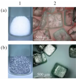
der before and after sputtering with Pt, respectively. Be- fore sputtering, the NaCl sample was white and the shape of each particle was obscure. After sputtering, the NaCl sample changed from white to metallic and the cubic shape of the particles was clearly seen because of their apparent contrast. Optical microscopic images of the untreated and treated NaCl particles are presented in Figure 2(2). The untreated NaCl particles were trans- parent and their surfaces were relatively rough (Figure 2(2a)). Following treatment, all of the particles were a uniform metallic color and their clear shading visibly emphasized the roughness of the original surfaces of the NaCl particles (Figure 2(2b)). Overall, the NaCl parti- cles were uniformly covered with metallic films by the polygonal barrel-sputtering method.
The NaCl particles before and after sputtering with Pt were observed by FE-SEM and EDS. The results ob- tained at low magnification (×110) are presented in Fig-ure 3 (a: before, b: after sputtering). The FE-SEM im- ages reveal that the treated and untreated particles pos- sessed similar morphology (Figure 3(1)). In the EDS mapping images, however, Pt element was detected only for the sputtered particles, as shown in Figure 3(2). Re-markably, the shape of Pt mapping is similar to those of Na and Cl mappings, suggesting that the Pt films were uniformly deposited on the NaCl particles. It is empha- sized that a relatively smooth surface was observed in an FE-SEM image obtained at a high magnification of ×190,000 (Figure 4), implying that the deposited Pt films contained no remarkable pores or damage.
The deposited Pt films were also characterized by XRD. Figures 5(a) and (b) show XRD patterns of NaCl samples before and after sputtering with Pt, respectively,
[image:2.595.59.284.542.706.2] [image:2.595.360.486.578.709.2]Figure 3. (1) FE-SEM images and (2) EDS mapping images of NaCl particles in the samples (a) before and (b) after sputtering with Pt (magnification: ×110).
Figure 4. FE-SEM image of the surface of a NaCl particle after sputtering with Pt (magnification: ×190,000).
obtained in the 2θ range of 30˚ - 50˚. Before sputtering, two peaks were observed at 2θ = 32.06˚ and 45.44˚, which were assigned to the NaCl(200) and NaCl(220) peaks, respectively, that are characteristic of NaCl with a cubic structure (JCPDS No. 05-0628). The XRD pattern of the Pt-sputtered sample contained two additional peaks at 2θ = 39.99˚ and 46.39˚ along with the diffraction peaks of NaCl. The new peaks in this pattern correspond to the signals of Pt(111) and Pt(200), demonstrating that the deposited films consisted of Pt metal with a face-cen- tered cubic structure (JCPDS No. 04-0802). However, the observed Pt peaks were slightly broad. In our previ- ous study on the surface modification of Al2O3 particles
with Pt films, broadness of the Pt peaks was attributed to the thinness of the layer of deposited Pt [19]. On this basis, the appearance of broad Pt peaks in Figure 5(b) most likely shows that the Pt films deposited on the NaCl particles were very thin.
The physical properties of the NaCl sample coated with a film of Pt metal were further examined by an im- mersion test. Photographs of the sample in a bottle con- taining pure water during the immersion test are shown in Figures 6(A)-(D). After an immersion time of 0.5 min, the samples had sunk to the bottom of the bottle (Figure 6(A)), clearly indicating that the NaCl particles were completely covered with the Pt films. However, some samples floated up the surface of the solution after 1 min (Figure 6(B)). The number of the floating particles gradually increased as the immersion time extended (Figure 6(C)). After 2 min, all of the particles floated at the surface (Figure 6(D)). It should be noted that the
Figure 5. XRD patterns of NaCl samples (a) before and (b) after sputtering with Pt.
Figure 6. Photographs of NaCl particles covered with Pt films in a bottle containing pure water after immersion times of (A) 0.5 min, (B) 1.0 min, (C) 1.5 min, and (D) 2.0 min. (E) Intensity of Cl peak obtained by XRF measure- ments of the solution used for the immersion test as a func- tion of immersion time.
floating particles retained their cubic shape, as seen in the magnified photograph of Figure 6(C).
Figure 7. (1) Photographs, (2) FE-SEM images, and (3) EDS mapping images of (a) Au and (b) Cu-sputtered NaCl parti-cles (magnificationof FE-SEM and EDS images: ×110).
of NaCl was not attributed to the collapse of the Pt films, but to the permeation of water through the Pt films. Re- member that there were no remarkable pores or damage in the Pt films formed on the NaCl particles, as depicted in Figure 4. Therefore, it is assumed that the deposited Pt films contained invisible defects such as grain bo- undaries through which water molecules could permeate, resulting in gradual dissolution of the NaCl particles. Furthermore, the tendency of the particles to float sug- gests that the permeation of water through the Pt films was very slow, leading to the formation of hollow parti- cle-like materials. This unique characteristic may be useful in biomedical applications such as drug-delivery systems [33,34].
Sputtering with Au and Cu was also performed to inv- estigate the effect of the kind of sputtered metal on sur- face modification of the NaCl particles. Photographs of the samples after sputtering with Au and Cu are illus- trated in Figures 7(1a) and (1b), respectively. For both samples, their color changed to that originating from the sputtered metals. When the particles in each sample were observed by FE-SEM and EDS, Au or Cu was detected correspondingly and the EDS mapping images reflected the SEM images (see Figures 7(2) and (3)). From Figure 7, it is clear that coating the NaCl particles with a uni- form film is achieved by our sputtering method inde- pendent of the kind of sputtered metal.
4. Conclusion
In this study, NaCl particles coated with metal films were prepared using the polygonal barrel-sputtering method. Metal films composed of Pt, Au, or Cu were uniformly deposited on all of the NaCl particles, demonstrating that the polygonal barrel-sputtering method can be used for surface modification of water-soluble and water-reactive particles. In addition, based on the results of this study and our previous reports, our sputtering method makes it
[1] P. Tolmacsov, A. Gazsi and F. Solymosi, “Decomposi- tion and Reforming of Methanol on Pt Metals Supported by Carbon Norit,” Applied Catalysis A: General, Vol. 362, No. 1-2, 2009, pp. 58-61.
doi:10.1016/j.apcata.2009.04.015
[2] B. Grbic, N. Radic, Z. Arsenijevic, R. Garic-Grulovic and Z. Grbavcic, “Structure Sensitivity of Dimethylamine Deep Oxidation over Pt/Al2O3 Catalysts,” Applied Catalysis B:
Environmental, Vol. 90, No. 3-4, 2009, pp. 478-484. doi:10.1016/j.apcatb.2009.04.008
[3] M. Ruta, N. Semagina and L. Kiwi-Minsker, “Monodis- persed Pd Nanoparticles for Acetylene Selective Hydro- genation: Particle Size and Support Effects,” The Journal of Physical Chemistry C, Vol. 112, No. 35, 2008, pp. 13635-13641. doi:10.1021/jp803800w
[4] J. S. Jang, S. H. Choi, H. G. Kim and J. S. Lee, “Location and State of Pt in Platinized CdS/TiO2 Photocatalysts for
Hydrogen Production from Water under Visible Light,” The Journal of Physical Chemistry C, Vol. 112, No. 44, 2008, pp. 17200-17205. doi:10.1021/jp804699c
[5] L. M. Torres-Martínez, R. Gómez, O. Vázquez-Cuchillo, I. Juárez-Ramírez, A. Cruz-López and F. J. Alejandre- Sandoval, “Enhanced Photocatalytic Water Splitting Hy- drogen Production on RuO2/La:NaTaO3 Prepared by
Sol-Gel Method,” Catalysis Communications, Vol. 12, No. 4, 2010, pp. 268-272.
doi:10.1016/j.catcom.2010.09.032
[6] L. J. Fu, H. Liu, C. Li, Y. P. Wu, E. Rahm, R. Holze and H. Q. Wu, “Surface Modifications of Electrode Materials for Lithium Ion Batteries,” Solid State Sciences, Vol. 8, No. 2, 2006, pp. 113-128.
doi:10.1016/j.solidstatesciences.2005.10.019
[7] Z. B. Wang, G. P. Yin and P. F. Shi, “New Pt-Ru Solid Compounds as Precursors of Anodic Catalysts for Direct Methanol Fuel Cell,” Journal of Alloys and Compounds, Vol. 420, No. 1-2, 2006, pp. 126-132.
doi:10.1016/j.jallcom.2005.10.042
[8] Y. Chen, Y. Zhou, Y. Tang and T. Lu, “Electrocatalytic Properties of Carbon-Supported Pt-Ru Catalysts with the High Alloying Degree for Formic Acid Electrooxidation,” Journal of Power Sources, Vol. 195, No. 13, 2010, pp. 4129-4134. doi:10.1016/j.jpowsour.2010.01.054
[9] B. N. Popov, X. Li, G. Liu and J.-W. Lee, “Power Source Research at USC: Development of Advanced Eelectro- catalysts for Polymer Electrolyte Membrane Fuel Cells,” International Journal of Hydrogen Energy, Vol. 36, No. 2, 2011, pp. 1794-1802. doi:10.1016/j.ijhydene.2009.12.050 [10] V. M. Aroutiounian, A. Z. Adamyan, E. A. Khachaturyan,
[image:4.595.67.281.82.231.2]Ruthenated SnO2/MWCNTs Nanocomposite Thick-Film
Gas Sensors,” Sensors and Actuators B, Vol. 177, 2013, pp. 308-315. doi:10.1016/j.snb.2012.10.106
[11] H.-K. Lee, H.-Y. Lee and J.-M. Jeon, “Codeposition of Micro- and Nano-Sized SiC Particles in the Nickel Matrix Composite Coatings Obtained by Electroplating,” Surface & Coatings Technology, Vol. 201, No. 8, 2007, pp. 4711- 4717. doi:10.1016/j.surfcoat.2006.10.004
[12] Y.-G. Zhou, N. V. Rees and R. G. Compton, “Nanoparti- cle-Electrode Collision Processes: The Electroplating of Bulk Cadmium on Impacting Silver Nanoparticles,” Che- mical Physics Letters, Vol. 511, No. 4-6, 2011, pp. 183- 186. doi:10.1016/j.cplett.2011.06.015
[13] Y. Xiang, L. Yang, W. Cheng-biao, L. Xin-chun and Y. De-yang, “Investigation on Preparation and Properties of Thick DLC Film in Medium-Frequency Dual-Magnetron Sputtering,” Vacuum, Vol. 80, No. 4, 2005, pp. 324-331. doi:10.1016/j.vacuum.2005.06.002
[14] M. Alvisi, G. Galtieri, L. Giorgi, R. Giorgi, E. Serra and M. A. Signore, “Sputter Deposition of Pt Nanoclusters and Thin Films on PEM Fuel Cell Electrodes,” Surface & Coatings Technology, Vol. 200, No. 5-6, 2005, pp. 1325- 1329. doi:10.1016/j.surfcoat.2005.07.093
[15] C. Lee and J. Bae, “Oxidation-Resistant Thin Film Coat- ing on Ferritic Stainless Steel by Sputtering for Solid Oxide Fuel Cells,” Thin Solid Films, Vol. 516, No. 18, 2008, pp. 6432-6437. doi:10.1016/j.tsf.2008.02.045 [16] T. Wang, X. Diao and X. Wang, “Inhomogeneous Opto-
electronic and Microstructure Property Distribution across the Substrate of ZnO:Al Films Deposited by Room Tem- perature Magnetron Sputtering,” Applied Surface Science, Vol. 257, No. 23, 2011, pp. 9773-9779.
doi:10.1016/j.apsusc.2011.06.010
[17] T. Abe, S. Higashide, M. Inoue and S. Akamaru, “Surface Modification of Fine Particles with a SnO2 Film by Using
a Polyhedral-Barrel Sputtering System,” Plasma Chemis- try and Plasma Processing, Vol. 27, No. 6, 2007, pp. 799-811. doi:10.1007/s11090-007-9100-4
[18] M. Hara, Y. Hatano, T. Abe, K. Watanabe, T. Naitoh, S. Ikeno and Y. Honda, “Hydrogen Absorption by Pd-Coat- ed ZrNi Prepared by Using Barrel-Sputtering System,” Journal of Nuclear Materials, Vol. 320, No. 3, 2003, pp. 265-271. doi:10.1016/S0022-3115(03)00189-2
[19] T. Abe, S. Akamaru and K. Watanabe, “Surface Modifi- cation of Al2O3 Ceramic Grains Using a New RF Sput-
tering System Developed for Powdery materials,” Journal of Alloys and Compounds, Vol. 377, No. 1-2, 2004, pp. 194-201. doi:10.1016/j.jallcom.2003.12.053
[20] S. Akamaru, S. Higashide, M. Hara and T. Abe, “Surface Coating of Small SiO2 Particles with TiO2 Thin Layer by
Using Barrel-Sputtering System,” Thin Solid Films, Vol. 513, No. 1-2, 2006, pp. 103-109.
doi:10.1016/j.tsf.2006.01.056
[21] T. Abe, H. Hamatani, S. Higashide, M. Hara and S. Akamaru, “Surface Coating of Small SiO2 Particles with
a WO3 Thin Film by Barrel-Sputtering Method,” Journal
of Alloys and Compounds, Vol. 441, No. 1-2, 2007, pp. 157-161. doi:10.1016/j.jallcom.2006.07.132
[22] A. Taguchi, M. Inoue, C. Hiromi, M. Tanizawa, T. Kita-
mi and T. Abe, “Study of the Surface Morphology of Pla- tinum Thin Films on Powdery Substrates Prepared by the Barrel Sputtering System,” Vacuum, Vol. 83, No. 3, 2009, pp. 575-578. doi:10.1016/j.vacuum.2008.04.023
[23] T. Abe, M. Tanizawa, K. Watanabe and A. Taguchi, “CO2
Methanation Property of Ru Nanoparticle-loaded TiO2
Prepared by a Polygonal Barrel-Sputtering Method,” En- ergy & Environmental Science, Vol. 2, No. 3, 2009, pp. 315-321. doi:10.1039/b817740f
[24] S. Akamaru, M. Inoue, Y. Honda, A. Taguchi and T. Abe, “Preparation of Ni Nanoparticles on Submicron-Sized Al2O3 Powdery Substrate by Polyhedral-Barrel-Sputter-
ing Technique and Their Magnetic Properties,” Japanese Journal of Applied Physics, Vol. 51, No. 6, 2012, Article ID: 065201. doi:10.1143/JJAP.51.065201
[25] T. Abe, S. Akamaru, K. Watanabe and Y. Honda, “Sur- face Modification of Polymer Microparticles Using a Hexagonal-Barrel Sputtering System,” Journal of Alloys and Compounds, Vol. 402, No. 1-2, 2005, pp. 227-232. doi:10.1016/j.jallcom.2005.02.097
[26] A. Taguchi, T. Kitami, H. Yamamoto, S. Akamaru, M. Hara and T. Abe, “Surface Coating with Various Metals on Spherical Polymer Particles by Using Barrel Sputter- ing Technique,” Journal of Alloys and Compounds, Vol. 441, No. 1-2, 2007, pp. 162-167.
doi:10.1016/j.jallcom.2006.07.131
[27] S. Akamaru, H. Yamamoto and T. Abe, “Surface Coating of Microparticles with Tungsten Carbide by Using the Barrel Sputtering System,” Vacuum, Vol. 83, No. 3, 2009, pp. 633-636. doi:10.1016/j.vacuum.2008.04.052
[28] H. Yamamoto, K. Hirakawa and T. Abe, “Surface Modi-
fication of Carbon Nanofibers with Platinum Nanoparti- cles Using a ‘Polygonal Barrel-Sputtering’ System,” Ma- terials Letters, Vol. 62, No. 14, 2008, pp. 2118-2121. doi:10.1016/j.matlet.2007.11.039
[29] M. Inoue, H. Shingen, T. Kitami, S. Akamaru, A. Ta-guchi, Y. Kawamoto, A. Tada, K. Ohtawa, K. Ohba, M. Matsuyama, K. Watanabe, I. Tsubone and T. Abe, “Pre- paration and Physical and Electrochemical Properties of Carbon-Supported Pt-Ru (Pt-Ru/C) Samples Using the Polygonal Barrel-Sputtering Method,” The Journal of Physical Chemistry C, Vol. 112, No. 5, 2008, pp. 1479- 1492. doi:10.1021/jp075400o
[30] M. Inoue, T. Nishimura, S. Akamaru, A. Taguchi, M. Um- eda and T. Abe, “CO Oxidation on Non-Alloyed Pt and Ru Electrocatalysts Prepared by the Polygonal Barrel- Sputtering Method,” Electrochimica Acta, Vol. 54, No. 21, 2009, pp. 4764-4771.
doi:10.1016/j.electacta.2009.04.009
[31] M. Inoue, S. Akamaru, A. Taguchi and T. Abe, “Physical and Electrochemical Properties of Pt-Ru/C Samples Pre- pared on Various Carbon Supports by Using the Barrel Sputtering System,” Vacuum, Vol. 83, No. 3, 2009, pp. 658-663. doi:10.1016/j.vacuum.2008.04.042