2017 2nd International Conference on Information Technology and Industrial Automation (ICITIA 2017) ISBN: 978-1-60595-469-1
Terminal Sliding Mode Based Vector Control
of Permanent Magnet Synchronous Motor
Yong Hou and Tong Zhang
ABSTRACT
In the field-oriented vector control strategy of permanent magnet synchronous motor (PMSM), conventional PI regulators are often used to realize controls of speed loop and current loop, which have some shortcomings such as weak anti-interference ability and poor robustness. In this paper, the terminal sliding mode control method is applied to PMSM field-oriented vector control. Combining the terminal sliding mode theory with the PMSM mathematical model, a joint control method for both speed loop and iq loop is proposed, which can improve the system control performance and reduce the controller number. The effectiveness of the proposed control strategy is verified by matlab/simulink simulation.
INTRODUCTION
Permanent magnet synchronous motor (PMSM) has a series of advantages and is widely used in many fields. At present, the common used PMSM control strategies are field-oriented vector control and direct-torque control[1, 2] and traditional PI controller is often used which can meet the system control requirements to some extent. Yet, the PMSM is a typical multi-variable, strong coupling, nonlinear system, the PI controller is difficult to achieve high precision control effect. So far, many improved control methods for PMSM are proposed which can improve the robustness and dynamic performance of the system [3], among which the sliding mode variable structure control (SMC) has many
________________________
advantages such as insensitivity to system mathematical model, strong robustness to system parameters perturbation and external disturbance, and therefore is increasingly used in PMSM control. And yet, the conventional SMC method adopts the linear sliding mode function, the system state converges to the given value asymptotically in the infinite time. Whereas the terminal sliding mode (TSM) variable structure control method introduces a suitable nonlinear term in the sliding mode function, which can converge the system state to the given value in a limited time and improve the steady-state tracking accuracy. In literature [5-7], the TMS control is applied to PMSM control, and good control effects are obtained.
In this paper, a magnetic field orientation control method for PMSM based on TSM is proposed. The TSM controller is designed for the speed loop in PMSM vector control strategy. Moreover, the q-axis stator current loop used in common vector control strategy is integrated into the TSM controller in combined with the speed loop. In this method, only a separate d-axis current controller is required for stator current control, which can improve the system control performance and simplify the system control implementation process.
FIELD-ORIENTED MATHEMATICAL MODEL OF PMSM
In the field-oriented control of PMSM, the system model in two-phase synchronous rotating coordinate system is[1]:
d d d d q q
q q q q d d f
u Ri L i L i
u Ri L i L i
(1)
Select the surface type PMSM. The electromagnetic torque can be expressed as:
e p f q d q q d p f q
3 3
( )
2 2
T n i L L i i n i
(2)
The mechanical motion equation is written as:
p
e L
( )
n T T J
(3)
where, ud, uq: stator d, q axis voltage (V); id, iq: stator d, q axis current (A); Ld, q
L
: stator d, q axis inductance (H); R: stator resistance (Ω); f: permanent magnet
flux (Wb); : rotor angular velocity (rad/s); Te, TL: electromagnetic torque and load
torque (N.m); J: rotational inertia (kg.m2); np
PMSM VECTOR CONTROL STRATEGY BASED ON TERMINAL SLIDING MODE
The TSM control was proposed by Zak in 1988 and has been concerned widely and applied extensively [4]. In this method, the TSM surface is designed as:
/
0
q p
s x x
(4)
where, x is the system state, the parameter β> 0; p, q are positive odd numbers and q<p<2q. The solution of differential equation (4) is obtained as
( )/ ( )/
[ ( )p q p (0)p q p] p
x t x t
p q
The convergence time from x(0)0 tox0 is:
( )/
s (0)
( )
p q p
p
t x
p q
It is obvious that the TSM control makes the system state converge to zero in finite time, which has fast response speed and high tracking precision.
The PMSM control first considers the speed reference value tracking, for which TSM controller is designed. Select the speed deviation as the system state variable, namely: e* where, * is speed reference value. From equation (3), we have
p
* *
e L
( )
n
e T T
J
(5)
According to the formula (4) and its parameter constraints, the TSM surface is designed as
/
q p
s e e
(6)
In order to reduce the chattering, the exponential convergence law is selected [8]. That is
sgn 0, 0
s s ks k
(7)
/ 1
( / ) q p
s e q p e e
(8)
From (2) and (5), one can obtain the following:
p p
*
p f q L
3 2
n n
e n i T
J J
(9)
With equations (1), (7), (8), (9) and ignoring the influences of the sudden speed reference change and the load torque disturbance, the q-axial voltage of PMSM can be written as:
q / 1
q q d d f 2
p f
2
[ ( / ) sgn ] 3
q p
JL
u Ri L i q p e e s ks
n
(10)
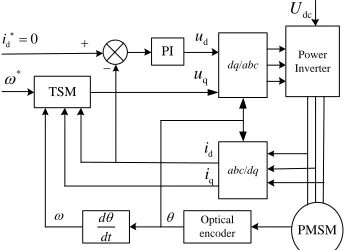
The equation (10) is the calculating formula of terminal sliding mode controller for speed loop. Reference value of uq is directly obtained from this equation. In other words, the speed control and the q-axis current control involved in the traditional vector control strategy are integrated into one controller, which can reduce the number of controllers and simplify the control process. Meanwhile, for the d-axis current control, the traditional PI controller is adopted as usual. The system control block diagram is showed in figure 1.
SIMULATION ANALYSIS
In order to verify the improvement effect, simulations both for the control strategies based on the proposed TSM controller and the traditional PI controller respectively are conducted by Matlab / Simulink. The simulation parameters are listed in Table 1.
Assuming that the reference speed is 1500r/min and the load torque is TL = 5N.m at beginning; the load torque is changed to 10N.m at 0.15s and the speed reference value is changed to 1000r / min at 0.3s.
CONCLUSIONS
On the basis of traditional PMSM field-oriented control strategy, a controller based on TSM is designed for the speed, which can realize fast and accurate speed tracking control. Furthermore, q-axiscurrent control in the traditional vector control strategy is integrated into the TSM controller, and only the d-axis current is independently controlled. The simulation results show that the proposed control strategy has faster speed response, higher control precision and better system stability compared with the traditional PI control method.
TSM
dq/abc InverterPower
PI
abc/dq
PMSM
d i
q
i
Optical encoder
d 0
i ud
dc
U
*
q
u
d dt
[image:5.612.103.276.247.372.2]
Figure 1. System control diagram.
Table 1. Parameters set for simulation.
R 2.875 Ω
Ld=Lq 0.0085 H
f
0.175Wb
np 2
Udc 600V
q/p 5/7
ε 50
k 300
β 1800
Figure 2. Simulation results of speed Figure 3. Simulation results of torque.
REFERENCES
1. Yu Pei-Chang, Wu Jun, Zhou Wen-wu. The Design of Vector Control System of PMSM [J]. Power Electronics, 2011, 45(11):105-107.
2. Han Chongwei, Chen Tengfei, Li Wei, Yang Gang, Zhang Zhipeng. Technology Evolvement Trend of Direct Torque Control for Permanent Magnet Synchronons Motor [J]. Micromotors, 2016, 49 (01):76-81.
[image:5.612.103.486.412.528.2]4. Zak M. Terminal Attractors for Addressable Memory in Neural Networks. Physics Letter, 1988, 33(12):18-22.
5. Zhang Niao-Na, Xu Xiang-Jun, Lin Xiao-mei. Direct Torque Control of Permanent Magnet Synchronous Motor Based on Two Order Sliding Mode [J]. Micromotors,2010,(10):33-35. 2010,(10):33-35.
6. Tong linghua. High-Order Terminal Sliding Mode Control for Permanent Magnet Synchronous Motor [J]. Electric Machines & Control Application, 2016,43(12):1-5.
7. Lei Xiaoben, Tan Haijun, Chen Zhuo, Li Shuwei. Global Fast Terminal Sliding Mode Controller of Permanent Magnet Synchronous Motor [J]. Micromotors, 2013, (11):38-41. 8. Gao Weibing.Theory and Design Method of Variable Structure Control [M].Science Press,