2017 2nd International Conference on Manufacturing Science and Information Engineering (ICMSIE 2017) ISBN: 978-1-60595-516-2
Research on an Automatic Leveling and
Positioning Control System
Hongjun Yang and Pan Zhu
ABSTRACT
A high-precision horizontal platform is needed for many engineering and military devices. This paper presents an automatic control device which can adjust the horizontal degree and position of the platform supported by four legs automatically. The device is controlled by PLC and positioning module, with the functions of detecting virtual legs and limit protection. The close-loop structure of control system is designed and a unidirectional control algorithm is proposed. The experiment showed that the device can adjust the level of the platform to 0.5°in 3 min1.
KEYWORDS
PLC, Platform, Automatic Leveling, Automatic Positioning
INTRODUCTION
Many devices require a high-precision horizontal platform when working properly such as vehicle-mounted radars, artillery launchers, gravity pressure piling machines, disconnecting switch box, etc.[1]. In the past, these devices were adjusted manually, which result in the shortcomings of time consuming and low accuracy [2]. In recent years, there have been some automatic leveling systems, including hydraulic and electromechanical systems, which have improved the accuracy and efficiency of leveling[3-4]. Most of these leveling devices were used in the heavy equipment such as automotive radar, but for some small equipment such as the
disconnecting switch box which is widely used in power system, the auto-leveling technology is researched very few. Moreover, fewer studies were done for the platform which is needed to adjust level and position at the same time.
CONTROL PRINCIPLE ANDSYSTEM STRUCTURE
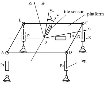
Usually the auto-leveling and positioning device consists of a movable platform and some support legs. If the number of legs is less than 4, the resisting overturning ability of the platform is poor. But it's difficult to control if the number of legs is more than 4. So this system adopts a four-leg support scheme. Because of the complex structure of the hydraulic system and the high requirement for the components, the electromechanical drive scheme is chosen for this system. The structure of the platform is shown in figure 1. Each leg is powered by a servo motor. Moreover the platform is driven by two horizontal electrical motors to adjust the horizontal position. The working principle is as follows. Two tilt sensors are placed on the platform in X and Y direction, used to detect the levelness of the platform, and then the PLC is used to control the rise and fall of four legs to adjust the levelness, meanwhile two motors of X and Y direction are controlled by the positioning module to adjust the horizontal position of platform.
Figure 1. Structure of the platform.
Figure 2. General frame of leveling system.
HARDWARE DESIGN OF CONTROL SYSTEM
According to the need of input-output points and the capability extended, the PLC, Mitsubishi FX3U-64M, is selected as the controller for the system. Compared the PLC of Mitsubishi FX2U, the PLC has more excellent performance, powerful function and three high-speed pulse output interfaces up to 100 KHz. But it has no interpolation function, so it can’t accurately control the line movement. While the Mitsubishi special positioning module is very suitable for two axis positioning, with the advantages of better coordination, accuracy, availability and economy. So the Mitsubishi special position, FX2N-20GM, is used to control two stepper motors in X and Y directions to adjust the level position of the platform. The20GM module is composed of the built-in power supply, CPU, various I/O interface, memory, various internal software and other hardware.
According the need of leveling, the title sensor with the model of
Z0
Y0
X0
X Z
0
platform tile sensor
Y
A
P1
B
P4
leg
D
P2
C
P2
level sensor and conversion circuit
position and toque sensors
platform screws
PLC OP
[image:3.612.148.424.276.421.2]Compared with other products, it has many advantages, such as small volume, low power consumption, high shock resistance and reliability. The platform does not need to carry too much weight, so the electro-mechanical drive is selected. Six stepping motors are selected to drive the device and a dual color touch screen is used to monitor the running state and input the operating parameters of PLC.
SOFTWARE DESIGN
The leveling strategy of the platform must be consistent with the action process of the platform. The pose transformation matrix is used to describe the state change of the rigid, which includes position change and posture change. The position and posture of platform change constantly in the process of leveling platform. The adjustment mechanism of the platform is parallel in space. The pose transformation matrix of platform between two coordinate systems can be derived from coordinate transformation. Assuming that the platform rotates the angle around the Y axis and then rotates the angle around the X axis, the position transformation matrix can be concluded as equation(1).
R=
cos sin sin sin cos
0 cos sin
sin cos sin cos cos (1)
The X and Y directions can be leveled at the same time or in order, but the leveling time is almost the same. Because there is coupling and it is hard to program when adjusting two directions at the same time, the one-way decoupling leveling method is proposed in this paper, which can decouple the spatial parallel mechanism into a plane problem. Because the fall of the leg can cause the leg hanging phenomenon, namely the virtual leg, so the legs should be lifted only during leveling. First the highest point of the platform is found by tilt sensor and stay fixed, and then the other leg is increased in order. For example, for adjusting the level of Y direction, if the angle β> 0, which indicates that the Y axis negative direction is higher than the positive direction, let two legs of B and C fixed, then increase the legs of A and D. That is to let AD spin clockwise around BC until the angel of Y direction meet accuracy requirement. The adjustment of another direction is the same as that.
EXPERIMENT AND RESULT
ACKNOWLEDGMENT
The work is supported by the scientific research fund of Wuhan Polytechnic University (2016y06).
REFERENCES
1. Hongjun Yang and Gangyan Li. 2008. “Study on leveling method and control technology of a vehicle-borne platform,” J. Machinery Design & Manufacture, no. 12: 134-136.
2. Jiangsheng Ni and Yujian Zhai. 1994. “Horizontal Adjustment of Radar Antenna Truck,” J. Measurement & Control Technology, 13(4): 36-39
3. Jingming Xie, Jiayong Cao and Youping Chen. 2004. “Research and development of vehicle hold automatic adjusting level system based on servo,” J. Electric Drive Automation, 26(2):
33-35.