The
AL
I
Arch
itecture
Descr
ipt
ion
Language
Uma
ima
Ha
ide
r
Dept. of Engineering & ComputingUniversity of East London London
UK
uha
ide
r@c
lemson
.edu
John
D
.
McG
rego
r
School of ComputingClemson University South Carolina
USA
johnmc@c
lemson
.edu
Rab
ih
Bashroush
Dept. of Engineering & ComputingUniversity of East London London
UK
r
.bashroush@qub
.ac
.
uk
Abstract
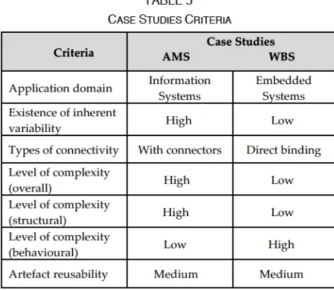
Architecture Description Languages(ADLs) have emerged overthe pasttwo decades as a meansto abstract details oflarge-scale systems in orderto enable betterintellectual control overthe complete systems. Recently,there has been an explosioninthe number of ADLs created intheresearch community. However,industrial adoption ofthese ADLs has been ratherlimited. This has been attributed to various reasons, includingthelack of support of some ADLsfor: variability management, requirementstraceability, architectural artefact reusability and multiple architectural views. To overcometheselimitations,this paperis a report on ALI, an ADLthat was designedto complement existing work by adding mechanismsto addressthe aforementionedlimitations. The ALI design principles, concepts, notations andformal semantics are presentedinthis paper. The notationisillustrated usingtwo distinct case studies, onefromtheinformation systems domain – an Asset Management System(AMS); and anotherfromthe embedded systems domain - a Wheel Brake System (WBS).
Categories and Subject Descriptors
D.3.3 [Software and its engineering]: Software system structures – software architectures
General Terms Design, Language.
Keywords:Software architecture,Architecture descriptionlanguages
1. INTRODUCTION ANDMOTIVATION
Within the software engineering community, the concept of software architecture startedto emerge as a distinct discipline in 1990 [1] which led to an explosion of interest duringthe 1990s and 2000s, referredto asthe “Golden Age of Software Architecture” [2]. Today, software architecture is growing fromits adolescencein researchlaboratories to theresponsibilities of maturity, which was predicted by Shaw [3] over a decade ago. But that does not mean that thetimefor research,innovation, and enhancementis past. In fact, it brings an additional responsibility to show not just that ideas are promising (adequate grounds to continue research) but also that they are effective (indispensable grounds to moveinto practice) [3]. In other words,itis a coupling between ongoing research and
actual applicationto make newideas practical. Forthis reason, software architecture has drawn considerable attention from both academia andindustry.
The increasing complexity of software and the critical nature ofits use are driving a rapid maturation ofthefield of software architecture. According to Garlan [4], a critical issue in the design and construction of any complex software systemisits architecture; thatis,its organization as a collection of interacting elements – modules, components, services, etc. Thus, a well-designed architecture ensures the quality and longevity of a softwaresystem. A number of approaches existthatcan describe a software architecture, ranging from formal notations (e.g. ADLs), semi-formal (e.g. UML) and informal (e.g. boxes andlines, videos, etc.).
Architecture Description Languages (ADLs) are currently considered to be viable tools for formally representingthe architectures ofsystems at areasonably highlevel of abstractionto enable betterintellectual control overthe systems [5]. AnidealADLis consideredto be both human-readable and machine-readable. An ADL must be simple, understandable, encompassed by multiple architectural views and syntacticallyflexible. With regards tothis, Lago et al. [6] presented a generalframework of requirements for the next generation architectural languages by taking into account current architectural needs of both the academic andindustrial worlds.
Over the past two decades, a number of ADLs [7] have been developed as compared to the number of ADLs reported in [8], [9] but the majority of the problems have not been resolved. Amongthose, afrequent problemisthat ADLs have gained wide acceptance in the research community as a means of describingsystem designs but their currentindustrial adoptionlevelis still reportedto be aslow as before with some exceptions, for example,in the embedded systems domain [10-13].This could be due to a number of reasons identified in [14-16], including the mismatch between their strengths and the needs of practitioners.
particular application domain(e.g. embedded systems). While domainspecific notations can be welltailoredto serve particular application area needs,today’ssystems (and system-of-systems) cross traditional design boundaries, where software persists across various layers (e.g. Cyber-physicalsystems, Smart Citiessystems, etc.). Thus, to be able to use an ADL in such domains, it would need to have the flexibility and expressiveness that allows it to stretch beyond a single application domain.
There hasrecently been anincreaseinthe usage of variability mechanisms atthe architecturallevel(e.g.to represent product families or runtime system adaptation). Variability management allows a)the development and evolution of different versions ofsoftware and product variants, b) planned reuse of software artefacts, and c) well-organized instantiation and assessment of architecture variants [17]. An ADL withthe capabilityto capture and express such complex variability exhibited in software systems would empower architects to build and model more sophisticated systems.
To overcome these aforementioned limitations, we propose ALI - an Architecture Description Languagefor Industrial Applications [18]. ALI hasbeen designedto be a comprehensive language, suited for different types of systems,fromindividualsystems,to productlines, and system-of-systems. A major goal of ALIisto provide a blend offlexibility andformalism. Flexibility meansitis easierto use andinformative enoughto conveythe needed information to the stakeholders involved in the architecting phase. Formalism, onthe other hand, paves the way for developing better tool support and automated analysis. ALIis designed to be highly customisable to provide support for a wide range of application domains. ALI is built on existing literature, and takes into consideration thelatest recommended guidelines [4, 6, 16] and characteristics [14].
Theremainder ofthis articleis organised asfollows: Section 2 discusses the current literature while highlightingthelimitations of existing work. Section 3 presentsthe design principles behind ALI andthe h igh-level (abstract) description of ALI in the form of a conceptual model. Section 4 covers the details of the language, visiting the different constructs in the ALI notation. Section 5 describes ALI structural and behaviouralsemantics. Section 6illustrates,throughtwo case studies, the ALI ADL. Evaluation of the case studies and the analysis are then discussed in Section 7. Section 8 discusses the study limitations. Finally, Section 9 concludesthe paper by summarizingtheimportant points and outlining future research directions.
2. LITERATUREREVIEW
Several ADLs [7] have been developed over the past two decades. Existingliteratureis critically analysedinthe next subsection, with limitations discussed in the following one.
2.1 Critical Appraisal of Existing Work
Since the early 90’s, a thread of research on formal architecture descriptionlanguages(ADLs) has evolved. Many different ADLs have been proposedin theliterature for modelling architectures both within a particular domain, and as general-purpose architecture modelling notations.
Allthe classical ADLs(also consideredfirst generation ADLs [19])compared and analysed by Medvidovic and Taylor [8] were conceptually based on structural architecture modelling features (components, connectors, interfaces and architecturalconfiguration). Another ADL survey was conducted by Clements [9] inthesame era. Some of the second generation ADLs have been compared in[20] butit covers a verylimited number of characteristics of thelanguages.
Reflecting on existingliterature,itisinteresting to note that veryfew ADLs were originatedinindustry. Described below are the three widely cited ones.
AADL [10] (Architecture Analysis & Design Language) derived fromthe MetaH [21] ADL,is a SAE standard formal modellinglanguagefor describing software and hardware system architectures and uses a component-based notation for the specification of task and communication.It provides precise executionsemantics for system components, such as threads, processes, memory, and buses. All externalinteraction points of a component are defined as features. Data and events flow through and across multiple components. The AADL Behavioural annex describes nominal component behaviour andthe Error annex describesflowsinthe presence of errors.
Koala [12] is a component oriented ADL based on key conceptsfrom Darwin [22]. Basically,it was designed with the aim of achieving a strict separation between component and configuration developmentin orderto reuse software components in many different configurations for different product variants, while controlling cost and complexity.
Although these ADLs come from differentindustries, they allrelatetothe embeddedsystems domain. AADL and EAST-ADL emerged from the avionics and automotiveindustries and are currently widely usedin theirrespective domains. Koala, onthe other hand, was developed within the consumer electronics domain, though its use has not seen the same proliferation as the previous two. These industrial ADLs, that are limited (perhaps by design) to the embedded systems application domain, would not be suitableto model cross-domain applications (e.g. Cyber-Physical applications encompassing embedded as well as Information systems).
Onthe academicside, alarge number of ADLs have been proposed, each characterised by slightly different conceptual architectural elements; different syntax or semantics; varying emphasis on asingle view(structural or behavioural) or operational domain such as embedded system; or for specific analysis techniques.
Below are some of the ADLs developedin academia: • ACME [24] is a general purpose ADL proposed as
an architecturalinterchangelanguage.
• Darwinis a declarative ADL whichisintended to be a general purpose notation for specifying the structure of distributed systems composed from diverse component types using diverse interaction mechanisms [22].
• UniCon [25] creates a useful, pragmatic and extensible test-bed that would allow the architectural abstractions used by practitioners (such as pipes,filters, objects, clients and servers)to be captured and reasoned about in a systematic manner.
• xADL[26], an XML based architecture description language, is defined as a set of XML schemas and has been designed to use the standard XML infrastructure and to be easily extensible using standard XML-Schema extension mechanisms. • C2is a component- and message-based ADL which
simplifiesthe definition of architecturesfollowing the Chiron-2 (“C2”) style [27].
• Rapide [28] is an event-based concurrent ob ject-oriented language specifically designed for prototyping architectures of distributed systems. • WRIGHT [29] is designed with an emphasis on
analysis of communication protocols and provides formal semantics for an entire architectural description by extending Communicating Sequential Processes(CSP) [30]. Wright has been extended, termed Dynamic WRIGHT [31], with the
ability to handle foreseen dynamic reconfiguration aspects of architecture.
According to the ANSI/IEEE 1471-2000 standard, structural and behavioural viewpoints are thetwo most important and frequently used viewpoints for architectural description. The specification of each viewpoint withtheir entitiesis elucidatedin [19, 32]. A great challenge for an ADL is being able to describe static and dynamicsoftware architecturesfromstructural and behavioural perspectives.
ADLslike ACME [24], Aesop [33], Aspectual-ACME [34], Darwin[22], Koala[12], MontiArcHV[35], UniCon[25], Weaves [36] and xADL [26] werefocusedlargely onthe structural concerns of software architecture. On the other hand, some ADLs covered both behavioural and structural specifications, including: AADL [10], ABC/ADL [37], ADLARS [13], ADML [38], C2 [27], CBabel [39], EAST -ADL [11], LEDA [40], MetaH [21], PrimitiveC [41], PRISMA [42], Rapide [28], SOADL [43], xADL [26], XYZ/ADL [44], vADL[45], WRIGHT[29, 31], Zeta[46], π -ADL [19] and π-SPACE [47]. Only a few ADLs cover behavioural aspects,such as Monterey Phoenix [48], yet, these ADLs do nottreat behaviour as afirstclasscitizen (tend to be merged with structural description).
Additionally, most of these languages (except [22, 29]) define structural elements using their own bespoke notation. Some ADLs(such as AADL) have a corelanguage that contains constructsfor representing structural and behavioural aspects of the architecture. Some used different processes to define the behavioural description. For example, Rapide describes behaviour through partially ordered event sets(or “posets”);Wright uses CSP with minor extensions; LEDA, PRISMA, SOADL, vADL, π-ADL and π-SPACE use the π-calculus.
based onthesystem under development(rather than an ADL restriction).
There are few second generation academic ADLs that focus mainly onthe behavioural modellingin aslightly different way as compared to traditional ADLs. Monterey Phoenix [48] is an ADL in which behaviour of the system is defined as a set of events (event traces) with two basic relations: precedence and inclusion. Different types of patterns (such as alternative, optional, etc.) are defined in the form of an event trace that occursin a transaction. But theylackthe unique visual notationfor each ofthese event patterns. A schema is defined as a set of transactions that includes all possible event traces. It can be tedious to understand(especially visually) andsometimes becomes more complicated whenitis encapsulated withseveral patterntypesin a single schema, particularly,inthe case of large-scale and complex systems.
PrimitiveC-ADL [41] is acomponent-basedlanguage that modifies the application architecture by subdividing components into subsystems of static and dynamic elements. A design pattern typically shows relationships andinteractions between components’ dynamic behaviour parts. The decision policy proposesthe use of a design pattern andthe application ofthe decision policy depends on a scenario. The main problemin[41] and other ADLs [19, 45] isthat whilethey definethe behaviour ofthe system within a component or in their configuration, behavioural elements are not explicitly defined. In other words, it provides a single view of the system whichis not suitable for a large-scale industrial system where component behaviour varies enormously. In that case, component definition becomes complex and it is difficult to differentiate static and dynamic parts.
AspectLEDA [57] is an ADL that provides behavioural specification ofthesystem usingthe UML usecase and activity diagrams by adoptingthe Aspect-Oriented(AO) approach. Each use case diagram represents a component that constitutes the system and its interactions are expressedintheform of sequence diagrams. Subsequently, a sequence diagram for every use case contains by default an aspect component as each use caseis extended with an aspect. In other words,it describes theinteractions among components visually via a UML sequence diagram withits dependency on an AO approach. Looking at this, componentinteractions need to be more elaborativein a sense by considering component interfaces (or ports) that are involved in the interaction which would be helpful to design complex systems.
Another major element that needs attention with regardsto ADLs,isthe concept of variability. Thisis a very important and critical area when it comes to its use in the architectural description, especially in large-scale industrial applications [13, 58]. Variability is the ability to designfor a planned set of changesfor deploymentin
specific contexts [17]. It facilitates the development of different variants of asystem architecture. Variabilityis largelytakeninto accountinthe architecture and design phase of software engineering [59]. Althoughthere are several ADLs where variability has been studied, variation isspecificto describing aset ofrelated products asin a software productline(SPL). Amongthe ADLs are: PL-AspectualACME [60], ADLARS,
EAADL
[61],
L ightPL-ACME [62],
vADL
,
and
DSOPL
[63].
Other
ADLs
that
cons
ider
var
iab
i
l
ity
as
a
separate
ent
ity
are
:
MontiArcHVand ∆-MontiArc [64].
Software architecturetypically plays a keyrole as a bridge betweenrequirements andimplementation [4].In terms of ADLs, a challenge in bridging this gap is how to trace feature (requirements) into the architecture description particularly,into each architectural element. Sofar,intheresearchliterature, ADLARS and L ightPL-ACME arethe onlytwo ADLsthat made an attemptto capture
the
re
lat
ionsh
ip
between
the
system
's
features
and
the
arch
itectura
l
structures
.
Both
assumed
a
feature
mode
l
as a precursor to the architecture design process and werelimited to specifying a productline.Itis worth mentioning that there are few ADLs that try to represent different aspects and domains in the architecture by presenting it in the form of different versions. Each focuses on a particular aspect/domain. For instance, ACME has been extendedto AspectualACME withits descendant PL-AspectualACME, LightPL-ACME, Cloud-ADL [65] and ADML; MontiArc [66] to MontiArcHV, ∆-MontiArc and MontiArcAutomaton [67].
Thereis aframework known as ByADL(Build Your ADL) [68] thatsupports asoftware architectureteamin definingtheir own ADL by allowing software architectsto (i) extend existing ADLs with domainspecificities, new architectural views, or analysis aspects,(ii)integrate an ADL with development processes and methodologies, and (iii) customise an ADL. Basically, it takes the meta-model of the ADL to be extended as aninput.
Overall, a common pitfallforthe discussed ADLsis their limited ability to support large-scale real-life applications. Some possible reasons behind this are discussed in [14, 16]. Limitations are further discussed in the next section.
2.2 Limitations within Existing ADLs
After critically analysing the existing ADL literature, particularly around scalability and uptake (industrial adoption), it was evident that only ADLs that were originated in industry saw some level of industrial adoption. This has been attributed to potential misalignment between practitioner needs and the academic focus [16].
identified in ADLs that emerged from academic research, but failed to achieve any notableindustrial adoption: L1: Limited support for variability management
To manage the size and complexity of industrial systems, and with the current trend of delaying architectural decisions as much as economically feasible (and the shift of variability from hardware to software), it is valuable to have the capability of modelling variability adequately in the architecture design.
L2: No explicit mechanism to link requirements to architectural artefacts
Requirementstraceability has emerged as a main objective inindustry. Yet, withoutthesupportforcapturingsuch relationships at the architecture description stage, thelink between requirements and implementation becomes difficult to establish and maintain. For example, although AADL does not support modelling such relationships natively, tools such as AADL’s OSATE provide such mechanisms outside the core ADL.
L3: Application domain dependency
As can be seen from the previous section, many ADLs are tailored for a particular application domain, with embeddedsystems havingthe majority ofsuchsystems. However, giventhe waytoday’s systems are evolving with the rise oftheInternet of Things(IoT), Cyber-Physical Systems(CPS), and Smart Citiesto name afew,for an ADL to be capable of modelling a complete solution,it needs to cross cut multiple application domains.
L4:Restrictive syntax
Many ADLs impose a strict syntax and design principles on the architect (e.g. layered model, network model, etc.). Building ADLs in such a way allows the ADL designer to provide various automated architectural analysis. However,from a practitioner perspective,thelastthing neededisto beforcedtoreason aboutthesystemin a specific way.
L5: Lack of support for architectural artefact reusability Existing ADLs have been designed to support the abstraction of details; however,supportfor architectural artefactreuse across multiple projectsislacking. While architecture reuse has seen some success in specific domains, e.g.the automotive domain using AADL[10],the granularity ofreuseremainsrelativelysmall.In orderto supportlarge-scalereuse, ADLs would needto provide mechanismsto capturesome degree of variabilityinthe description of artefacts (and theirinterfaces) to enable redeploymentin multiple contexts.
L6: Overloaded architectural views
Giventhat one ofthe main benefits of having an overall system architecture description is to use it as a communication vehicle amongthe variousstakeholders, not alltheinformation captured withinthe architecture relate to every stakeholder. Accordingly, ADLs providing one or two architectural views tend to suffer from information overload. The importance of having multiple architectural views has also been highlightedin [32]. L7: Focus on structure more than behavioural architectural aspects
The structural description of a system changes less frequently compared to the behavioural description because systems can serve different objectives withthe same structural description. In other words, the structural description can encapsulate morethan one behavioural description. Yet, it can be said that most ADLs still overlooktheimportance of behavioural description. While it is viewed as a major construct in some [10, 28], it is not coveredin many [25, 29, 36], with fewer ADLs supporting the representation of behavioural architectural knowledge graphically [69].
In the following sections, we discuss theALI ADL [18], which builds oninitial work donein [70],to overcome theselimitations.
3. DESIGNPRINCIPLES
Analysing the practitioner’s needs as discussedin [16, 71], and in the literature review as discussed in Section 2, our goalisto design alanguagethatissimple enoughto be usable in an industrial setting, yet formal enough to adequately support automated analysis and other essential functionalities(extensibility, evolution,traceability etc.), though thelatter is outside the scope of this paper.
To achievethis goal, we presenttheset of principles, which were usedto drivethe development ofthe ALI notationin order to address thelimitations pointed outin the previous section. Additionally,this section provides an overview of ALI’s conceptual model.
3.1 Principles
Six general principles guided the creation of the ALI ADL:
P1: Variability management
variability needsto betreatedin asimilar wayto other essential functionalities of the architecturallanguage.
Our proposed ALI ADLtreats variability as a first class citizen and managesit as anintegral part of thelanguage. It providesthe abilityto manage variability not onlyinthe overall system architecture description but also in the design ofindividual architectural elements – interfaces, connectors and components. Thisis done with the help of a simpleif/else structure concept along withthe keywords “supported” and “unsupported”. Additionally, ALI supports variability management in its behavioural description using the same if/else structure (details in Section 4.1.12).
P2: Requirement traceability
Tracing requirements from the problem space (specification)into the solution space (implementation) provides a valuable tool for architects to help validate the produced system againstits set of objectives. However,for such an end-to-end traceability to work, there needs to be continuity in capturing relevant information at all development stages,including architecture.
ALI supports requirements traceability by supporting thelinkage of end-user features (see Section 4.1.2) directly to architectural elements (components, connectors, patterns etc.) using first order logic (to allow for complex dependencies).
Additionally, ALI supports ‘conditioning’ the behavioural aspects of the system to external parameters (see Section 4.1.10). Such conditions can also be usedto changethe behaviour ofthe system given various external requirements.
P3: Cross application domain modelling
Withthe emergence of new paradigms such astheInternet of Things (IoT) and Cyber-Physical Systems (CPS), architecture descriptions are now faced withthe challenge of encompassing multiple application domains. For example,if we consider the Smart Cities scenario, systems in this application domain will entail the applications running sensor platforms(IoT devices), communication gateways, databases (BigData infrastructure), and Information Systems that deliver end-user services. While the architecture ofthe sensor systems can be modelled using embedded-system oriented ADLs,these ADLs do not necessarily lend themselves to representing the architecture of Information Systems. Thus, there is a need for new generation ADLsthat arecapable of modelling system across traditional design boundaries.
ALIsupports cross-application domain modelling by introducing flexibilityinthe notation design at different levels. For example, ALI allows for the creation of custom interfacetypes using a dedicated notation. The case studies
discussedshow‘port’likeinterfaces, as well as‘WSDL’ interfaces.
P4: Balance formality and flexibility to better support the design process
Duringthe earlystages ofthe design process, architects tend to sketch things at a very highlevel, using merelines and boxes. At that stage, for example,itis difficult to start talking aboutthe details ofinterfaces between components or what meta information to capture about each architectural element.
As the system development process progresses, and as more details are captured aboutthe system, specific details in relation to architectural elements can then be discussed and modelled. Thus, an ADL needs to allow some flexibly at the initial stages of the design process, and at the same time, provide the required formality when details are available.
For example, ALI achieves this balance between formality andflexibility by allowing architectsto work with undefined interface types. When such informal interfaces are used, no automated analysis would be possible. Oncethe designis mature, andinterfacetypes are created, ALI couldthen provide an array of verification checks (as specifiedin theinterface type description).
P5: Increase architectural artefact reusability
Architectural artefacts tend to be tailored to particular system requirements. Accordingly, veryfew ADLs discuss the concept of artefact reusability across multiple systems. Yet,in real-life,itis more often than not we are faced with similar architectural challenges that could be solved using architectural artefacts we havein existing projects. ALI supportsthe concept oflarge-grain reusability by allowing architectural artefactsto be made configurable based on selected sets of features.
For example, componentsin ALI can be customised based on which features are selected for a particular component, andthe values ofthesefeatures. Similarly, connectors andinterfaces can also be parameterised using feature sets. By mapping the feature set of the source domain (where the componentis taken from) and the feature set of the destination domain (where the componentis goingto be deployed),the component can adapttothe new environment(further detailsin Section 4.1.6).
P6: Multiple architectural views
order to minimise information overload, and sacrifice abstraction for completeness, the need for multiple architectural views cateringfor differentstakeholdersis becoming animportant feature of an ADL.
ALI is designed with the concept of multiple architectural views, where each view correspondsto a stakeholder (or stakeholder group) and addresses a differentset of concerns(see Section 4.1fortextual and Section 4.2 for graphical descriptions).
3.2 Conceptual Model
A conceptual model is a high-level description of how a system is organized and operates [73]. The aim of a conceptual model is to express the meaning of terms and concepts used by domain experts andtofindthecorrect relationships between different concepts. Several notations [74-77] exist that are used to describe the conceptual model. Amongthose, UML(Unified Modelling Language) [74] is a widely used and comprehensive notation(ISO/IEC 19501).
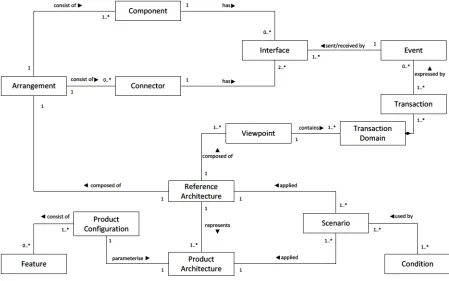
Fig. 1 showsthe conceptual model of ALI. The reference architecture represents the overall system description. The reference architecture is made up of arrangements and viewpoints. Arrangementsrepresentthestructural(static) description of the system and are composed of components
and connectors, which communicate throughinterfaces. Viewpoints aresets of transaction domains that pertain to a common concern (e.g. car ignition system). Transaction domains represent the behavioural (dynamic) aspects of the system, and are composed of sets of transactions that together serve a particular system feature (e.g. user/key validation). Transactions are expressedin terms of sets of events that achieve a system functionality (e.g. key authorisation). And events are the basic communication mechanism between components(e.g. key code update event).
Conditions are parametersthat represent external(tothe system) environmental aspects that could impact the system behaviour. The architecture description is parameterised using these conditions, which can be either true orfalse. Different combinations of conditions and their values, called scenarios, can be used to test and adapt the behaviour of the system to various contexts.
Finally, a product architecture can be derivedfrom a reference architecture using a product configuration. Product configurations represent desired features, andtheir values, for a specific productin a productline.
Inthe next section,the details ofthese constructs, along with the notation used to describe them, are discussed.
Fig. 1. ALI conceptual model
Interface
Connector
Event Component
Product Configuration
Transaction
Transaction Domain
Product Architecture
Reference Architecture
Scenario
Feature Condition
1..*
1
1..* 0..*
1..*
1..*
1..*
1 1
1
applied
applied parameterise
expressed by 1
0..* has
1..* 1..*
used by
0..*
1..* consist of Arrangement
1
has 1
1..*
1
0..*
represents 1 1
composed of
composed of
Viewpoint
1
1..*
1
1..*
contains
1 1..* 1
2..*
consist of consist of
[image:7.558.62.511.366.647.2]4. CONSTRUCTS ANDNOTATIONS
Woods and Bashroush [71] observed that architectural languages constructed with complex or obscure syntactical notations are rarely used correctly. Generally, practitioners avoid adopting complexlanguagesintotheir development process especiallyinlarge scale systems whereit becomes tediousto handle and understand. Malavolta et al. [16] conducted an industrial survey which shows that architecturallanguages needto besimple andintuitive enough to communicate the right message to the stakeholdersinvolvedinthe architecting phase along with some formality in order to drive analysis and other automation tasks. The ALI notation is designed accordingly, wherethesyntax(graphical andtextual)is keptsimple andflexible, yetformal enoughto conduct automated analysis.
In the following sections, we discuss the main constructs of the ALI notation. Where applicable, we demonstrate the concepts using parts of the Asset Management System (AMS). AMS is used to manage investment portfolios of financial instruments such as equities and commodities (see Section 6.1 for further details).
4.1 ALI Textual Notation
The ALI textual notation is designed based on the principles definedin Section 3.1. Thetextual notationis made up of 14 main constructs aslistedin Table 1.
These constructs are discussed in the following sections.
4.1.1 Meta Types
The meta types section provides a formal syntax for capturing meta-information ofthe architectural element (e.g. components, connectors, etc.). A meta typeis defined by theinformationit encompasses. Theinformationis storedinfields, where eachfield has a name(tag) and a data type (text, number, etc.). The following example defines a meta type calledMeta_ServerEquity
:
meta type Meta_ServerEquity {
tag creatorID, intention: text; tag cost, version*: number; tag last_updated: date; }
Inthis example, “metatype”is a keyword whichis used to start a meta type definition.Meta_ServerEquityis the name of the meta type being specified. Each meta type contains a set of tags each of which is either textual, numeric, date, enumeration or character. Five tags are definedinthe above example:twotextual,two numeric and one date. The asterisk“*” ontheversiontagindicates thatitis an optional tag.
TABLE1 ALICONSTRUCTS
Construct Description
Meta types Provide an extensible mechanism for capturing architectural meta-information
Features The system features are catalogued
Interface templates Specifies a dedicated notation for creating categories of interface types
Interface types Architecturalinterfaces are defined
Connector types Architectural connectors are defined
Component types Architectural components are defined
Pattern templates Reusable architectural design patterns are defined
Product configurations Provides the feature combinations that characteriseindividual products
Events The events that flows within a system are defined
Conditions The system behavioural conditions (architecture parameterisation) are catalogued
Scenarios Behavioural scenarios are defined (sets of conditions to represent a runtime scenario)
Transaction domains Provides the behaviouralinteractions within a particular system domain
Viewpoints Different behavioural viewpoints are defined
Once meta types are specified, meta objects conforming to these types can be created and attached to architectural elementsthroughoutthe architectural description. These meta objects provide an areafor appending additional information related to these elements.
Below is an example of a meta object that conforms to the meta type definedin the example above.
meta: Meta_ServerEquity { creatorID: “Martin005”;
intention: “Acts as a mediator to manage equity portfolio”;
cost: 5,000; version: 1.3;
last_updated: 20-02-2017; }
A meta object could also be a combination of morethan one metatype. To enhancethelanguageflexibility,itis also possible to create meta objects that do not conform to any meta type. However, little automated analysis can be performed on such informally described data. The reason for allowing objects with no type is to enable architects to sketch whattheyinitiallythinkcould berelevant meta-information, then, once confirmed, they create the appropriate meta types to ensure conformance.
Theformal specification of metainformation allowsfor easier CASE tool development to harness these meta objects and conduct automated analyses (e.g. cost/benefit analysis, project timing/scheduling, etc. depending on whattype of metainformationis available). Other meta informationcouldinclude: design decisions,component compatibility, etc. which when extracted andformatted using proper CASEtools, allow automated architecture documentation to be achieved on-the-fly.
In general,itis expectedthatthe metatypes will be created once and used repeatedly across the different systems developed bythe same enterprise.In orderto make surethat criticalinformationis always provided within an architecture description, a project management team (or any other stakeholder) may firstidentify the standard set of information required (tags), and then provide it to architects for conformance. The flexibility in the syntax also allows the architects to augment this information withfields(tags)thatthey may wantto use internally within the architecture team.
4.1.2 Features
Thefeature description notation provides a catalogue of the system features (mandatory, optional or alternative) used within the system. The feature definition comprises of:
• alternative names: In many cases, different teams withinthe development process address afeature with different names. This sub-section ofthefeature definition keepstrack ofthe different names(if any) that are used to address the same feature. This property will keep track of the system features and reduce redundancy.
• parameters: Afeature can carry differenttypes of parameters -textual, numerical and Boolean. Though, not all features would be parameterised.
Belowis an example of howfeatures are definedin ALI: features {
Equity: {
alternative names: {
Designer.FI1, Developer.Ey, Evaluator.F11;
}
parameters: {
{Equity_Type = text}; }
}
Equity_Derivative: { alternative names: {
Designer.ID1, Developer.SD, Evaluator.F14;
}
parameters: {
{Derivative_Type = text, Premium_Period = text, OTC = boolean}; }
}
// similarly other features can be defined }
In the example above, Equity_Derivativewas defined showing thatitis referred to asID1by the design team, SD bythe developmentteam, andF14bythe evaluationteam. Thefeature encompassesthree parameters,twotextual and one Boolean.
In ALI, systemfeatures are definedin a stand-alone catalogue as shown above. The catalogue serves as an adapter between anyfeature modellingtechnique used andthe architecture description, making ALIindependent of any particular feature modelling technique.
4.1.3 Interface Templates
RMI, etc.) needed within an application domain once, and reuse themin different projects. Theseinterface templates can be used as a specificationin defining the interface types ofthesystem, either explicitly(as explainedinthe next section) or in the component type definition (Section 4.1.6). This template specification can also be reused outside the defined system depending uponthe design requirement as per principle P5in Section 3.1.
The interface template definition is divided into three main sections:
• providersyntax definition: wherethesyntax ofthe provider interface is specified using a subset of the JavaCC [78] notation. JavaCC (Java Compiler Compiler)is an open source notationthat allowsthe definition of grammars using EBNFstylesyntax [79]. TheJavaCC specification canthen be compiled to produce a parser for a particular interface definition.
• consumersyntax definition: wherethesyntax ofthe consumerinterface is specified using a subset ofthe JavaCC notation.
• constraints: where the interface connectivity constraints are specified. Theseinclude:
- Should match: here the terms (identified in the below syntax definition sections usingtheJavaCC notation) that should match between two interfacesto be considered compatible(allowedto bind) areidentified.
- Binding: comprises of three different fields: 1) multiple -a Boolean value that states whether multiple bindingis allowed onthisinterface; 2) data size -range of the data that can pass through this interface by providing the maximum and minimum values; and 3) max connections – maximum number ofsimultaneous connections allowed on theinterface.
- Factory: Thisis a Boolean valuethat states whether theinterfaceis afactory or not. Afactoryinterface means that when a connection requestis received on this interface, a new instance is created to handlethat particularrequest whilethe factory interface continues to listen to new incoming requests. Example: server socketinterfacesinJava arefactories. Onthe other hand, C++sockets do not support factory functionality by default. - Persistent: This is a Boolean value that indicates a
persistent interface (the internal data of the interface component is kept unchanged after the current connection has ended) whensettotrue andindicates atransientinterface(internal datais resettoinitial values whenthe current connection is terminated) when set to false.
An interface template description begins with the keyword “interfacetemplate” followed bytheinterface template name such asMethodInterface asinthe example below:
interface template MethodInterface { provider syntax definition: { "Provider"":"
"{"
{"function" <FUNCTION_NAME> "{"
"impLanguage" ":" <LANGUAGE_NAME> ";" "invocation" ":" <INVOCATION> ";" "parameterlist" ":" "("
[<PARAMETER_TYPE> {"," <PARAMETER_TYPE}] ")" ";"
"return_type" ":" <RETURN_TYPE> ";" "}" }
"}" }
consumer syntax definition: { "Consumer"":"
"{"
“Call” “:” <INVOCATION> “(“ [<PARAMETER_TYPE> {"," <PARAMETER_TYPE}] ”)” “;” "}"
}
constraints: {
should match: {INVOCATION_NAME =
.INVOCATION_NAME,PARAMETER_TYPE} binding: {
multiple: true;
data_size: [50KB, 500MB]; max_connections: 5; }
factory: false; persistent: false; }
} }
Itisimportantto clarify herethattheinterfacetemplate definition is not meant to be read by humans, but rather created once andthen read by CASEtoolsthat would verify theinterface descriptions and connections made throughout the architecture definition.
4.1.4 Interface Types
The interfacetype notation provides aset of pre-defined interface types that are created in conformance to the definition of an interfacetemplate, describedinthe previous section.Interfacetypes can be(re)usedinthe design of architectural elements (components and connectors) throughout the system description (design principle P5).
An interface type definition begins with the keyword “interface type” asin the example below:
interface type {
ArithmeticOperation: MethodInterface { Provider: {
function Addition {
impLanguage: Java; invocation: add; parameterlist: (int); return_type: void; }
function Subtraction {…} function Multiplication {…} }
Consumer: {
Call: getValue (long_int); }
}
AverageOperation: MethodInterface { Provider: {
function Average {
impLanguage: Java; invocation: average; parameterlist: (int); return_type: void; }
}
Consumer: {//nothing consumed} }
NumericOperation: MethodInterface { Provider: {
function GetValue {
impLanguage: Java; invocation: getValue; parameterlist: (void); return_type: long_int;
} }
Consumer: {
Call: add (long_int); Call: subtract (long_int); Call: multiply (long_int); Call: average (long_int); }
}
… //similarly other interface types can be defined
}
Each interface type is defined by a unique name followed by the interface template name, to which it conforms. In the example above, ArithmeticOperation performs basic mathematical operationsto calculatethe portfolio value based on the value it consumed and AverageOperation calculates the portfolio value by using the average formula strategy. The interface type NumericOperation consumes valuesreturnedfromthese interfacetypes and providesthemtothe otherinterface. They all conform to the interface template MethodInterface defined in the previous section. We can also define otherinterfacetypesthat conformto other interface templatessuch as WSDL, RMI, etc.
4.1.5 Connector Types
Like many other ADLs,such as ACME [24], Aesop [33], CBabel [39], EAST-ADL [11], UniCon [25], WRIGHT [31] and π-ADL [19], to name a few, connectors are considered first class citizensin ALI.
A connectortype definition begins withthe keyword “connectortype” followed bythe connectortype name and is dividedinto three sections.
connector type Calculator_Equity {
features: {
MTM_Price_Method: “Share prices matched with market price”, Company_Price_Method: “Unlisted share price of an individual company”,
Weighted_Average_Method:
“Portfolio Valuation is done on the basis of average share price”; }
interfaces: {
valueport1: ValueOperation; valueport2: ArithmeticOperation; valueport3: AverageOperation; valueport4: NumericOperation; }
layout: {
Company_Price_Method)) {connect valueport1 to valueport2;
connect valueport2 to valueport4;} else if (supported(Weighted_Average_Method))
connect valueport3 to valueport4; }
}
• features:a set of optional/alternativefeatures usedto parameterise a connector type. By changing feature values, a connector can be reconfigured to be deployedin different products(based onfeature availability and parameter values). The configurationis achieved using if/else structures and the keywords “supported/unsupported” to link features to the connector definition.
• interfaces: where the connector interfaces are defined along with their interface types. These resembletheinput/output ports oftheconnector. Basically,interfaces areinstances of interfacetypes that are definedin accordance to interface templates. • layout: The layout section describes the internal
configuration (structure/arrangement) of the connector. It demonstrates how the connector interfaces are connected internally, that is, how the traffic (information) travels internally from one interface to another. This syntax introduces a high level ofconfigurabilitytotheconnector definition which provides better support for defining configurable product and product line architectures. Two types of configurations are allowed between connectorinterfaces, namely: - uni-directionalconnections(to): whichspecifythat
the data from one interface goes to another interface. This is done using the keywords: “connect” and “to”. Example: connect valueport1 to valueport2inCalculator_Equityoutputs the data onthe valueport1interfacetothevalueport2 interface.
- bi-directionalconnection(and): whichspecifythat the data cantravelin bothdirections betweentwo interfaces. This is done using the keywords: “connect” and “and”. Example: connect valueport4 and valueport1 in Calculator_Equity outputs the data on the valueport4 interfacetothevalueport1 interface and vice versa.
Additionally, the keyword “all” can be used to connect a connectorinterfaceto all otherinterfaces ofthe connector using a bi-directional or unidirectional communication. For example, “connect all to all”can be used to create bi-directional connections among all ports. We can also
have “connect valueport1 to all”which makestheinput oninterface valueport1 available as output on all other interfaces of the connector.
Lastly, meta objects can be attached to connector types by simply definingthe meta object(as explainedin Section 4.1.1) inside the connector type definition (anywhere between the start and end brackets.
4.1.6 Component Types
The componenttype definitionis dividedintothree main sections:
• features: aset of optional/alternativefeaturesthat make up a component type. The purpose and definition ofthissectionis exactlysimilartothe concept offeatures definedinthe connectortype (see Section 4.1.5). That is, it provides the capability to reuse componentsin multiple products and systems by varying feature values (product configurations). • interfaces: which specifythe differentinterfaces used
by the component. Theinterfaces sectionis divided intotwosections, definition where newinterfaces can be created from scratch; and implements where already definedinterfaces can be reused (interfaces implemented here areinstances ofinterface types). • sub-system: where the internal structure (sub
-system) ofthe componentis described. The sub-system sectionis dividedinto three sections: - components: wherethe differentsub-components
included within the component are defined. - connectors: where the different connectors usedin
connecting sub-components are defined.
- arrangement: where the way in which sub -components are connected is described. To allow flexibility, ALI providesthree different methods that can be used to connect components:
a. Using connectors: where a connector mediates the connection between two or more components. This is done using the keywords: “connect”.
Example: connect component.interface1 with connector.interface1.
b. Direct binding: wherecomponentinterfaces are bound directly without the use of a connector. This is done using the keywords: “bind”. For example: bind component1.interface1 with component2.interface1.
For example, a component type description for a portfolio equity valuator(which calculatesthe portfolio value based onthe valuation method requested bythe fund manager) begins with the keyword “component type” followed by the component type name Portfolio_EquityValuator as shown in the example below.
component type Portfolio_EquityValuator {
meta: Meta_Valuator, Meta_ShareTradeData {
/* demonstrates meta object comprises of two meta types */
acceptance_value: “any numerical value”; value_approximation: “2 significant figures”; curreny_acceptance: “all top international trading currencies that exists in stock exchange”;
last_request: 18-01-2017;
intention: “to calculate the portfolio value on the basis of current business day trading”;
}
features: {
E_Share: “Type of equity in financial instruments”,
MTM_Rate_Method: “Share prices matched with market price”,
Company_Rate_Method: “Unlisted share price of an individual company”, Weighted_Average_Value_Method:
“Portfolio Valuation is done on the basis of average share price”; }
interfaces: { definition: {
//No need to define any interfaces }
implements:{
// MethodInterface interface template NumercialValue: NumericOperation; if (supported (MTM_Rate_Method || Company_Rate_Method)) //WSDL interface template PriceStatus: ValueData; if (supported
(Weighted_Average_Value_Method)) CalculationMessage: PortfolioMessenger; }
} //end of interfaces
sub-system: { components {
PValueProcessor<false, false, false, true, true, true>: Portfolio_Processor; if (supported(E_Share)) {
if (supported(MTM_Rate_Method)&&
unsupported(Weighted_Average_Value_Method)) MTMValuator<true, false, false, false>: EquityCalculator; else if (supported(Company_Rate_Method)) CRValuator<false, true, false, false>: EquityCalculator; else
WeightedValuator<false, false, true, false>: EquityCalculator; }
}
connectors {
HTTP_EMarket<MTM_Rate_Method, Company_Rate_ Method, false>: HTTP_EquityValuator; if (supported(MTM_Rate_Method) &&
unsupported(Weighted_Average_Value_Method)) Cal_MTM<true, false, false>:
Calculator_Equity; else if (supported(Company_Rate_Method)) Cal_CR<false, true, false>:
Calculator_Equity; else {
HTTP_VProcessor<true, false>: HTTP_Equity; HTTP_CalWAV<false, false, true>:
HTTP_EquityCalculator; Cal_WAV<false, false, true>:
Calculator_Equity;} }
arrangement {
// connecting components using connectors connect PValueProcessor.CalculationMessage with HTTP_VProcessor.msgport2; connect my.CalculationMessage with
HTTP_VProcessor.msgport1; if (supported (MTM_Rate_Method ||
Company_Rate_Method)){ connect PValueProcessor.PriceStatus with HTTP_EMarket.valueport1; connect my.PriceStatus with
HTTP_EMarket.valueport2;} if (supported(MTM_Rate_Method) &&
unsupported(Weighted_Average_Value_Method)){ connect PValueProcessor.CalculationValue with Cal_MTM.valueport1;
connect MTMValuator.OperationalValue with Cal_MTM.valueport2; connect my.NumericalValue with
Cal_MTM.valueport4;} else if (supported(Company_Rate_Method)) { connect PValueProcessor.CalculationValue with Cal_CR.valueport1; connect CRValuator.OperationalValue with Cal_CR.valueport2; connect CRValuator.OperationalValue with Cal_CR.valueport2; connect my.NumericalValue with
Cal_CR.valueport4;} else {
connect PValueProcessor.AverageRequest with HTTP_CalWAV.messageport1; connect WeightedValuator.AverageMessage with HTTP_CalWAV.messageport2; connect WeightedValuator.AverageValue with Cal_WAV.valueport3; connect my.NumericalValue with
Cal_WAV.valueport4;} } // end of arrangement section
} // end of sub-system section } // end of component type
The example above shows how the component configuration can change depending on what features are supported. The keyword “my” is usedtoreferencethe component’s owninterfaces as opposedto sub-component interfaces (similar to the use of “this” in some programminglanguages).
4.1.7 Pattern Templates
The pattern template notation in ALI allows the definition and use of architectural patterns. They arefirst defined and then(re)usedthroughoutthe architecture bycallingthe pattern template needed. The pattern template definition takes theinterfaces to be connected as an argument andis definedin a similar waytothe definition offunctions (methods)in programminglanguages. A pattern template definition comprises of:
• pattern name: a unique pattern name.
• arguments: a set ofinterfacesto be connected. Single interface and/or arrays of interfaces can be passed as arguments. The minimum and maximum number ofinterfaces passed can be specified as arguments for arrays ofinterfaces.
• definition: the description of how the interfaces are to be connected (the pattern). The syntactical notation usedfor defining patternsis verysimple and provides support for:
- connectinginterfaces: uses syntax similartothat usedinthe connectionssection ofthe connector type definition (discussedin Section 4.1.5). - definingloops:to allowfor connecting arrays of
interfaces. Thesyntax used hereissimilartothe syntax used in most programming languages for creating forloops. The pointto be notedisthatthe arrays ofinterfacesstart atindex 1 and not at 0 (likein most programming languages).
Below is an example that definesClient_Server pattern:
pattern templates: {
Client_Server (server : MethodInterface, clients [1…N] : MethodInterface) {
for ( i = 1 ; i <= N ; i++ ) connect clients[i] and server; }
}
In this example, theClient_Serverpattern takes as an argument one interface server of template MethodInterface,and an array ofinterfaces called clients (with[1..N] meaning atleast one client interface) of templateMethodInterface. The pattern is defined as: for allNclientsinterfaces, create a bi-directional connection withtheserverinterface(see Section 4.1.5 onthe use ofthe keywords: “connect”, “and”, and “to” for connecting interfaces).
4.1.8 Product Configurations
A product configuration is a set of features, along with their values, representing a particular product configuration (thisis alsocalled productfeatureset in Software Product Line Engineering). Product configurations can be used to generate specific products from the parameterised reference architecture. Below is an example product configuration for an Equity_Share_Derivativeproduct. product configurations {
Equity_Share_Derivative: { Equity {Equity_Type = long}; Equity_Share = true;
Equity_Derivative {Derivative_Type = options, Premium_Period = 1year, OTC = false};
Share_Sector {Holdings = 100,
… // similarly other products can be defined }
4.1.9 Events
Events are abstractions of actions performed duringthe execution ofthesystem,such as a messagetransmission from one componentto another.In ALI, events are defined using a unique name, along withtheinterfacetemplates theytravelto andfrom. Belowis an example of how to define events:
events {
ValuationRequest: <WSDL, WSDL>;
RequestValuationDetails: <MethodInterface, MethodInterface>; CalculateValue: <WSDL, WSDL>;
… }
Inthe above example, ValuationRequest is an event that flows between twoWSDLinterfaces. It is also possible for events to travel from, and to, more than one interface template. In this case,interface templates arelisted within parentheses andseparated by commas asshowninthe example below.
Inform: <(MethodInterface, WSDL), (MethodInterface, WSDL)>;
4.1.10 Conditions
Conditions are usedto parameterisethe system description to make it adapt to certain environmental conditions. Everyset of conditions(ascenario) canthen be usedto simulate a certain environmental situation(e.g.failure, market changes, etc.). These can be usedtotestthe waythe architecture definition can adaptto different operational changes(design principle P2). Conditions are defined with a unique name along with asimpletextual description. Belowis an example definition offour different conditions. conditions {
PriceChanged: “Change in share price”; PriceUnchanged: “No change in share price”; ShareTrade: “Buying/Selling of shares”; Exchange_Traded: “Shares listed in stock exchange”;
… }
4.1.11 Scenarios
Scenarios are basically collections of different conditions, along withtheir values, whichtogether can simulate a certain operational scenario. Belowis an example scenario description.
scenarios {
P.RevaluatingPC: {
Description: “Revaluating portfolio due to change in share price with no trading”; Parameterisation: {
PriceChanged = true; PriceUnchanged = false; ShareTrade = false;
} }
… // similarly other scenarios can be defined. }
In the above example, scenario P.RevaluatingPC demonstratesthe portfolio revaluation whenthereis a changein share price only. It encapsulates three conditions (defined in the previous section) in which one is true and two are false. Scenarios can be very useful when comparing different architectural configurations. Scenariosserve asswitches, and assuch, do notsupport parametrisation (which can be achieved in other parts of the notation, such as transaction domains).
4.1.12 Transaction Domains
Transaction domains representthe behavioural aspects of thesystem. Eachtransaction domaincomprises aset of components and connectors within a systemthat work together to achieve some system functionality (e.g. portfolio evaluation). Within atransaction domain, various transactions are defined, each describing a particular systemfunction orfeature (e.g. valuation processing, MTM valuation, etc.). Transactions are definedin terms of event flows.
TABLE2
ALITRANSACTIONDOMAINTEXTUALNOTATION
Notation Meaning
Component.Interface Component name withinterface name
* Component External component (or system)
Event Event name
Event/Connector Event traveling on connector
TRANSACTION Transaction name sends
receives from
to
Keywords describing the path of an event
if/else Alternation (OR Fork) | Alternation (OR Join)
, Concurrency (AND)
[…] Mu(concurrency) ltiple simultaneousinteractions (…) Grouping of events
; Interaction termination
Below is an excerpt of the PortfolioValuation transaction domain definition.
transaction domain PortfolioValuation {
/* Meta objects can be attached as discussed earlier in Section 4.1.1 */
contents: {
/*provides the list of components and connectors involved in this transaction domain*/
components: {Portfolio_GUI, UI_Server, EquityDb, Job_Processor, Value_Processor, Market_Share_Data, Equity_Market_Data, *Stock_Market, *Company_Financial_Account, UI_Price_Server,Portfolio_Value_Calculator, *P/L_System}
connectors: {HTTP_GUI, HTTP_Status, HTTP_Processor, HTTP_ExMRate,
HTTP_ExCRate, HTTP_CRate, HTTP_Price, HTTP_External, Cal_Processor,
DB_VProcessor} }
transactions: {
VALUATIONREQUEST: {…} VALUATIONUPDATE: {…} MTMVALUATION: {…} UNLISTEDVALUATION: {
events: {RequestPrice, CurrentPrice} interactions:
{
*Company_Financial_Account receives RequestPrice/HTTP_ExCRate; *Company_Financial_Account sends CurrentPrice/HTTP_ExCRate to UI_Price_Server.PriceStatus; UI_Price_Server.PriceStatus sends CurrentPrice/HTTP_CRate; }
}
REVALUATION: {…} VALUATIONPROCESS: {
events: {Inform, RequestPriceList, RequestPrice, CurrentPrice} interactions:
{
if (supported(Equity_Share)) { if (PriceUnchanged)
VALUATIONUPDATE receives
Inform/ODBC_Processor from VALUATIONREQUEST; else {
if (supported(MarkToMarket_Method && (Exchange_Traded))
MTMVALUATION receives
RequestPriceList /HTTP_Processor from VALUATIONREQUEST; else
UNLISTEDVALUATION receives RequestPrice/HTTP_ExCRate from VALUATIONREQUEST;}
[REVALUATION receives
CurrentPrice/HTTP_ExMRate from MTMVALUATION |
REVALUATION receives
CurrentPrice/HTTP_CRate from UNLISTEDVALUATION];
} //end of interaction } //end of transaction } //end of transactions section
} } //end of transaction domain
Given the wayinteraction domains represent event flows, graphical representations (discussed in Section 4.2) tend to work much betterin expressing complex flows.
4.1.13 Viewpoints
Viewpoints in ALI represent collections of transaction domains that relate to a particular stakeholder. A viewpoint definitionincludes: a unique name, description and alist of related transaction domains. Belowis an example viewpoint definition for PortfolioInvestment. viewpoints {
PortfolioInvestment: {
Description: “Investment made into the Portfolio”;
Transaction Domain: {PortfolioValuation, PortfolioRebalance,
PortfolioStrategy}; }
… //similarly other viewpoints can be defined }
4.1.14 System
Finally, the system notation describes the overall product (or productline) architecture. It uses very similar notation tothe component description section with some minor changes. For example,the system description provides support (using asterisk “*”) forlinking componentsto external (to the system) components or systems. Additionally, a system descriptionincludes alisting of viewpoints. Belowis an example system description.
system { components {
Portfolio_GUI<>: PortfolioAMS_GUI; UI_Server<false, false, false>:
Portfolio_EquityUIServer; Job_Processor<false, false, false, false, false, false>: Portfolio_Processor; EquityDb<true, false, false, false, false, false>: AMS_EquityDb;
if(supported(Equity_Share)){ // portfolio valuation
Value_Processor<false, false, false, true, true, false>: Portfolio_Processor; if(supported(MarkToMarket_Method) &&
unsupported(Share_Company_Method)){
Market_Share_Data<false, false, false, true, false, false>: AMS_EquityDb; *Stock_Market;}
else {
*Company_Financial_Account;
UI_Price_Server<false, false, true>: Portfolio_EquityUIServer;} }
Equity_Market_Data<false, false, false, true, true, false>: AMS_EquityDb; Portfolio_Value_Calculator<true,
MarkToMarket_Method, Share_Company_Method,
false>: Portfolio_EquityValuator; *P/L_System;
}
connectors {
HTTP_GUI<true, false, false, false>:
HTTP_AMSUserInterface; HTTP_Processor<true, false>: HTTP_Equity; DB_VProcessor<false, false>:
ODBC_EquityPortfolio; HTTP_Status<false, false, false, false>: HTTP_AMSUserInterface; if(supported(Equity_Share)){
if(supported(MarkToMarket_Method)) HTTP_ExMRate<false, true, false>:
HTTP_ExternalSystem; if(supported(Share_Company_Method)){
HTTP_ExCRate<false, false, true>:
HTTP_ExternalSystem; HTTP_CRate<false, true, false>:
HTTP_EquityValuator;} HTTP_Price<true, true, false>:
HTTP_EquityValuator; Cal_Processor<false, false, false>:
Calculator_Equity; HTTP_External<false, false, false>:
HTTP_ExternalSystem;} }
}
arrangement {
//similar to component type arrangement /* an snippet below demonstrates some of the connections related to revaluation transaction that have been presented visually in Figure 2 */
connect Portfolio_Value_Calculator. NumericalValue with
Cal_Processor.valueport4;
connect Value_Processor.OperationalValue with
Cal_Processor.valueport1;
connect Value_Processor.NotificationMessage with
HTTP_External.messageport1; connect *P/L_System with HTTP_External.messageport2;
connect Value_Processor.NotificationMessage with
HTTP_Processor.messageport1;
connect UI_Server.NotificationMessage with
HTTP_Processor.messageport2;
/* similarly other connections can be made via connectors */
}
viewpoints {
PortfolioInvestment; }
}
4.2 ALI Graphical Notation
Many ofthe existing ADLs such as AADL [10], ACME[24], Aesop [33], MontiArcHV [35], Darwin [22], Koala [12], UniCon [25] and π-ADL [19], provide bothtextual and graphical notations,though none provide a behavioural graphical notation. Yet,insome cases,the needforsuch graphical behavioural representation was argued, e.g. using Use Case Maps with ADLARS [13, 69]. ALI provides graphical notations for structural and behavioural aspects of the systems.
In ordertocreate aconsistent graphical notationthat was expressive and easyto use,thetheoretical guidancein [80] was followed. Furthermore, lessons learned from Woods and Bashroush in [71], designing a large-scale architectural description within anindustrial context, were also taken into consideration. The following sections discuss ALI’s graphical notation.
4.2.1 Structural Notation
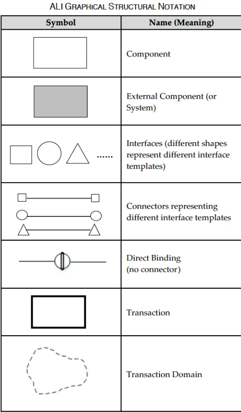
ALI provides an extensible visual notationforits structural description. Table 3illustrates the meaning of the symbols usedto specify architectural structuresin ALI. Itis possible to extend the notation to represent components by introducing other graphical objects (e.g. a cylinder to represent a databasecomponent)that architectsidentify with or already usein certain application domains.
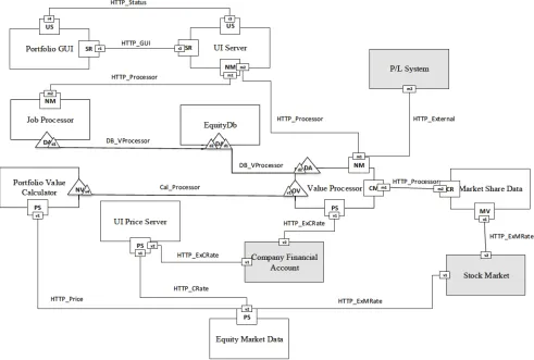
Fig. 2 represents the structural description of the Revaluation transaction (part of the PortfolioValuation transaction domain defined earlier in Section 4.1.12 in textual format). The same notation can be used to describe the whole system.
TABLE3
ALIGRAPHICALSTRUCTURALNOTATION
Symbol Name (Meaning)
Component
External Component (or System)
……
Interfaces (different shapes represent differentinterface templates)
Connectors representing differentinterface templates
Direct Binding (no connector)
Transaction
Transaction Domain
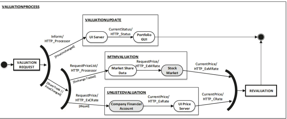
4.2.2 Behavioural Notation
4.2.2.1 Event Traces
In ALI, event traces constitute the graphical representation of transactions, describedtextuallyin Section 4.1.12. Table 4 providesthe detailed description ofthesymbols usedto design eventtraces. Some ofthe symbols used are adopted from the UML Activity diagram [74], with added notation to represent concurrency (based on some extended concepts from Petri Nets [81]).
Fig. 2. Graphical structural representationfortransactionRevaluation
Fig. 3. Graphical behavioural representation oftransaction domain PortfolioValuation
EquityDb
MTM VALUATION
Job Processor Portfolio Value
Calculator
Equity Market Data UNLISTED
VALUATION
P/L System UI Server Portfolio GUI
Value Processoror
[image:19.558.37.524.71.380.2] [image:19.558.39.527.440.644.2]TABLE4 ALIEVENTTRACESNOTATION
Symbol Name Meaning
START A node that starts theinteractionin an event trace by a component thatinvokes an event.
END A node that stops theinteraction of all the transactionsin an event trace.
FINAL A node that terminates theinteraction of the transaction.
EventName/Cr* Event Flow Theanother direct componention of an event, spec fifylowing from the event one component name and to the connector* being traversed.
AND Fork A source component sending two or more concurrent events to destination components.
AND Join
A destination component receives two or more concurrent events from source components. This blocks until all events are received before progressing.
OR Fork destA sourceination component components sends. Se onelect orion more of the events destinat toion components can belinked to system conditions and features.
OR Join Aany dest oneinat ofion the component source components receives any (non-b of thelock eventsing) as from soon asit arrives (without waiting for all expected events).
Component A component within the system that sends/receives events.
External Component/ System
A system (or component) outside the system that communicates with our system.
Transaction Transactionis a package containing a set ofinteractions. It can be nested wherever requiredin another transaction.
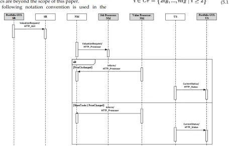
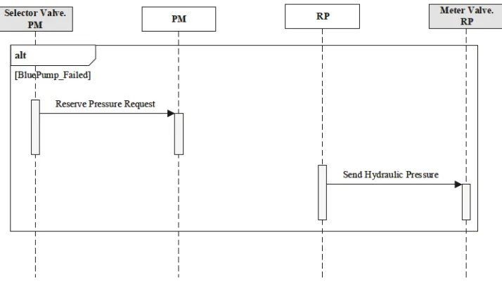
4.2.2.2 Component Interaction
Thissection providesthe graphical notation usedto describe the interactions of an individual component. While eventtraces modelthe complete eventflow path, component interactions focus on modelling t