IBM Internal Use Only
This publication is primarily intended for use by IBM personnel enrolled in TAl 40600.
First Edition (November 1987)
References in this publication to IBM products, programs, or services do not imply that IBM intends to make these available outside the United States.
A fonn for readers' comments has been provided at the back of tIlls book. If the form has been removed, address your comments to IBM Corporation, Service Education, PO Box 390, Department 1170, Building 947, Poughkeepsie, NY 12602.
Please include the order number in your comments.
IBM Internal Use Only
General Information
Technical Awareness Information (TAl)
Prerequisites
TAl Description
This mode of delivery has been selected because you are trained on the basic 3174 Subsystem Control Unit. No additional skills are required to service the 3174 Sub-system Control lJnit with the Asynchronous Emulation Adapter (AE!\') feature, but there is information you should have to aid in servicing the 3174 with this feature. The information presented does not require the Field Instruction Systeln (PIS) and is contained in this single document.
You are encouraged to send the author any comments about this TAl document. Because this is a new approach to providing update information to previous training, we are especially interested in your opinion. !\. reader's cOlnment fonn is provided at the back of this document for your convenience.
• Course Number 75021-3174 Subsystem Control Unit
This TAl document provides 3174 base trained CEs with additional technical infor-mation in order to service the 3174 with the AEA. The increased connectivity to ASCII devices/hosts provided by this feature is explained along with typical ASCII subsystem configurations.
The MLT (Multiple Logical Terminals) function of Release 3 microcode is pre-sented along with its application in the ASCII subsystem.
New tests arc presented along with updates to the maintenance package, online test screens, and some of the cllstOlnizing screens so that the CE will be familiar with the new service environment created by the AEA feature and Release 3 Inicrocode.
Materials and Instructions
Approximately one hour is needed to read tlus TAL Pay paliicular attention to the new subsysteln configurations created by this feature and to the changes to online test and custOlnizing screens with which you are already familiar.
Note: Time is recorded as service code 51 on QSAR.
IBM Internal Use Only
Related Publications
IBM 3174 Asynchronous Emulation Adapter Feature, ZZ2S-8S24 (this docu-ment)
IBM 3174 Subsystem Control Unit, Asynchronous Emulation Adapter: Introduc-tion, GA23-0331
IBM 3174 Subsystem Control Unit, Terminal User's Reference for Expanded Functions, GA23-0332
IBM 3174 Subsystem Control Unit, Models 1 L, 1 R, 2R, and 3R User's Guide, GA23-0337
IBM 3174 Subsystem Control Unit, Customer Extended Problem Determination, GA23-0217
IBM 3174 Subsystem Control Unit, Maintenance Information, SY27-2S72
IBM 3174 Subsystem Control Unit, Customizing Guide, GA23-0214.
IBM Internal Use Only
Contents
Introduction 1 Terminology 1
Terminal and Host Operating Sequence
AEA Feature 3
Asynchronous Emulation Adapter Hardware 3 Communications Links and Associated Hardware 6
Physical and l.ogical Paths 7 Physical Path 7
Logical Path 7 Printers 8 Display Units 9 Connectivity 10
ABA Major Functions 11
ASCII Subsystem Configurations 13 Host Attachment 16
Dual Control Units 19
Multiple Logical Terminals (ML1) 21 Active and Background Sessions 21 Change Screen Key 21
Case Study 22
ML T Customizing Scenario 22 ML T Operation Scenario 23
Customizing 25 Stations and Sets 25 Port Type and Port Sets 26 Customizing Screen Changes 28 Problem Determination Assistance 33
Maintenance Package Updates 35 New MAPs 35
New Status Codes 35 New Tests 35
Oflline Tests 35 Online Tests 36
Teleprocessing Network Support 45
Summary 47
List of Abbreviations 49
Glossary 51
Index 53
IBrvl Intcrnai Use Only
IBM Internal Use Only
Figures
1. ASCII Terminal and lIost Operation 2
2. Asynchronous Etnulation Adapter IIardware 4 3. ABA I/O Panel 5
4. Communications Equipment 6 5. Physical and Logical Paths 7 6. Printer Logical Path 8 7. Display Unit Logical Path 9
8. Overall Connectivity with AEA Feature 10
9. 3270 Terminal Emulation 13 10. ASCII Terminal Emulation 14 11. ASCII Passthrough 15
12. Connection Menu 16
13. Connection Menu Option 1 17 14. Connection Menu Option 2 17 15. 7232 Connection Diagram 19
16. Multiple Logical Tenninal Operation 22
17. Host Set and Terminal Set 25 18. Port Sets 26
19. Connected Terminal and Port Sets 27 20. Customize Control Diskette Menu 28 21. I-Iost Attachment 29
22. Port Assignment 30
23. Printer Authorization Matrix ( PAM) 31
24. Completed Printer Authorization Matrix (PAM) 32 25. Main Menu for Test 12 36
26. Asynchronous Emulation Adapter Port Tests Menu for Test 12 38 27. Logs Menu for Test I 39
28. Log Record Display Panel for Test 1 40 29. lIardware Configuration Table for Tcst 2 41
30. Status Summary for Test 3 42
31. Display Control Blocks Menu for Tcst 6 43
IBM Internal Usc Only
IBM Internal Use Only
Introduction
Terminology
The 3174 Asynchronous Emulation Adapter (ABA) feature and Release 3 micro-code provide the customer with increased connectivity by allowing the customer to:
• Use an ASCII device to cOInmurucate with an ASCII host • Use an ASCII device to communicate with an IBM host • Use a 3270 device to cOInmunicate with an ASCII host
• Use a 3270 CUT device in MLT (Multiple Logical Terminal) mode to have multiple sessions with ASCII and IBM hosts.
In order to understand the 3174 AEA subsystem nl0re thoroughly, you need to understand the terms used in this TAL These terms are explained in the "Glossary" on page 51.
Terminal and Host Operating Sequence
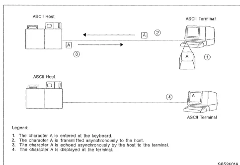
To help you further understand ASCII terminals and hosts, refer to Figure 1 on page 2 to see what is involved in entering and displaying data at an ASCII terminal.
IBM Internal Use Only
ASCII Host
ASCII Terminal
[
~
[QJ])
'--__
'----I
----J1f-0
- -
_~-===
__
--=-=~--
-_0_
A _@_2.
®
ASCII Host
w -
ASCII TerminalLegend:
1. The character A is entered at the keyboard.
2. The character A is transmitted asynchronously to the host.
3. The character A is echoed asynchronously by the host 10 the terminal. 4. The character A is displayed at the terminal.
[image:10.624.51.535.62.393.2]S852401A - - - _ . _ - - - ' Figure 1. ASCII Terminal and Host Operation. This diagram depicts the sequence of events from the time the
char-acter "An is entered at the ASCII terminal keyboard until it is displayed on the ASCII terminal screen.
This same sequence between ASCII hosts and terminals takes place for all data that is entered and displayed at an ASCII terminal.
For ASCII printers, the sequence is sitnilar, except that the data is sent, not echoed, from the host. It is sent one-character-at-a-time, asynchronously to the printer until all the desired data is printed.
This procedure of transferring data, one-character-at-a-time, asynchronously in seven bit code, is referred to as ASCII protocol. This is in contrast to 3270 pro-tocol, where the EBCDIC data is transferred multiple-characters-at-a-time in a 3270 data stream.
Keep these concepts in mind as the AEA feature and subsystem configurations are explained.
IBM Internal Use Only
AEA Feature
The AEA feature provides the capability to attach ASCII devices to the 3174 in addition to those 3270 devices that can be attached to a particular 3174 model.
Asynchronous Emulation Adapter Hardware
The Asynchronous Emulation Adapter feature hardware is installed by the cus-tOlner. Each AEA along with its associated cables and port connectors is capable of connecting eight ASCII devices, comprising any of the following types:
• Hosts • Display units • Printers.
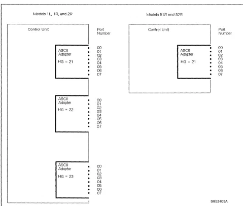
The 3174 Models 1 L, 1 R, and 2R support the installation of up to three AEA cards. When three AEA cards are installed, the 3174 is capable of connecting 24 ASCII devices, comprising the types listed.
Models SIR and 52R support the installation of one AEA card and, therefore, are capable of connecting eight ASCII devices, comprising the types listed.
Note: The 3174 Models 51 Rand 52R cannot contain both the Asynchronous Emulation Adapter feature and the IBM Token-Ring Network 3270 Gateway feature. Furthermore, the AEA feature is not available in a 3174 Model 53R.
Each AEA is identified by a hardware group (HG) number and each AEA port is identified by an AEA port number (see Figure 2 on page 4).
IBM Internal Use Only
Models 1 L, 1 R, and 2R Models 51 Rand 52R
Control Unit
l
Port Control Unit Port~~urnber Number
•
00•
00ASCII 01 ASCII • 01
Adapter • 02 Adapter 02
HG
=
21 ••
03 04 HG=
21 03 04•
05 • 05• 06 06
07 07
ASCII 00
Adapter • 01
HG = 22 • 02
• 03
• 04 05 06
• 07
ASCII • 00
Adapter 01
HG = 23
•
02 03 04• 05
• 06
• 07
I S852403A
Figure 2. Asynchronous Emulation Adapter Hardware
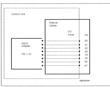
In addition to adapter card(s), the feature also includes an internal cable between each adapter card and an 1/0 panel. The 1/0 panel has eight 25-pin D-shell con-nectors. The AEA port connectors are nutnbered 0 through 7 and provide the method of connecting the communications link cables (see Figure 3 on page 5).
[image:12.626.57.537.64.471.2]IBM Internal Use Only
-Control Unit
Internal Cubles
I/O
Panel P~--J
.-
- - - -~ 00 ASCII e~ 01
Adapter
e 02
e- ~ 03
HG = 21 e
•
04.-
- -•
05e- - 06
e--
•
07S852404A
Figure 3. AEA I/O Panel
[image:13.624.180.553.59.353.2]IIlM Internal Use Only
Communications Links and Associated Hardware
3174 Control Unit
1 - - - 1
ASCII
Adapter
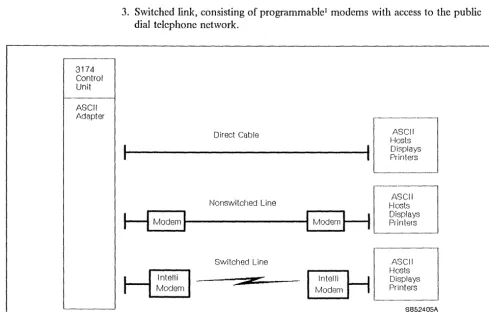
Three types of communications links as shown in Figure 4 are available. 1. Direct cable from the AEA to the host, display unit, or printer
2. Nonswitched link, consisting of dedicated modems and customer-owned/leased telephone lines
3. Switched link, consisting of programmable
' rllodems with access to the public dial telephone network.
Direct Cable
Hosts
D
-
AS-CII1---...
1
DisplaysPrinters
Nonswitched Line
H
ModernI
...
---tl
ModemH
Switched Line
*
ASCII
Hosts Displays Printers
' - - - '
[
ASCII
Hosts Displays Printers
S85240SA
Figure 4. Communications Equipment
'\..,
I Also referred to as a smart or intelligent modem.
[image:14.624.53.542.180.492.2]IBM Internal Usc Only
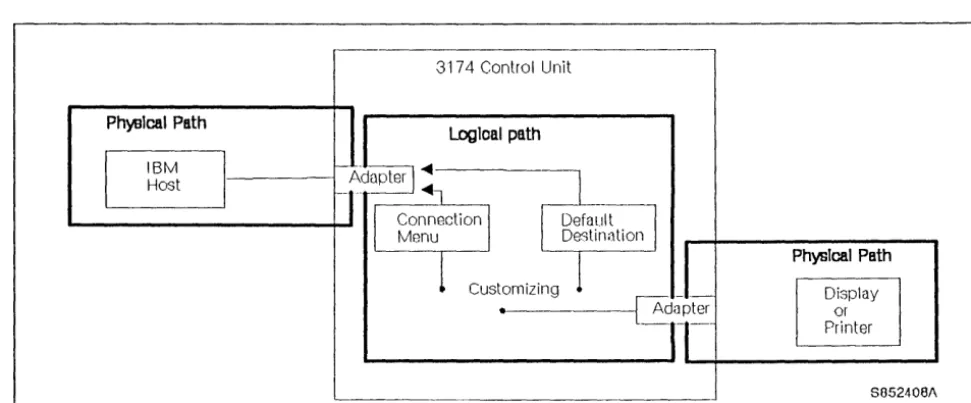
Physical and Logical Paths
Physical Path
Logical Path
The physical path between the control unit and various hosts, display units, and printers is determined by the hardware installed. Once this hardware is installed, the physical path generally remains the same.
The logical path is determined by customizing. This is accOlllplished by either selecting a default host or presenting a Connection Menu from which the host is chosen by the display unit user. The ability to customize the logical path makes it easier to change terminal user access to more that one host, particularly when adding new hosts (see Pigure 5).
3174 Control Unit
logIcal path
Ph~lcal Path
IBM
l
Host _---~
Customizing
Figure S. Physical and Logical Paths
PhysIcal Path
Display or Printer
8052408/\
[image:15.624.71.557.316.517.2]IBM Internal Usc Only
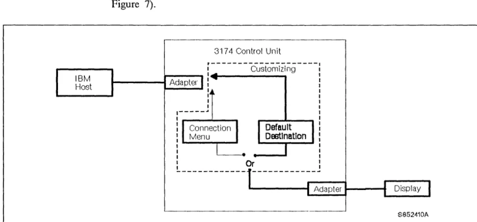
Display Units
Display units may be assigned to the Connection Menu or to a default host. If assigned to a default host, then the path is the same as the one for printers (see Figure 7).
- - - ,
3174 Control Unit
~---cu;~~Zi~g----~----~I~---~
I - - - t Adapter :
1 1 1 1
1---..
:,...---'----.
1 1
:---,....-.
...
1 1
L
____________
O~ ___________ _' - - - t Adapter 1 - - - 1
...
__
...
S852410A
Figure 7. Display Unit Logical Path
[image:17.623.73.559.121.347.2]IBM Internal Use Only
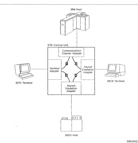
Connectivity
As the overall connectivity of the 3174 with AEA feature is described, refer to Figure 8.
3270 Terminal
IBM Host
3174 Control Unit
Terminal Adapter
Communication/ Channel Adapter
Asynch Emulation
Adapter
ASCII Host
Asynch
Emulation-Adapter
ASCII Terminal
S852402A
Figure 8. Overall Connectivity with AEA Feature. Two AEAs are shown to illustrate overall connectivity and the three major functions performed by the AEA.
[image:18.621.61.534.117.603.2]IBM Internal Use Only
Traditional Operation: Path
D
shows the traditional path between 3270 terminals and the IBM host.AEA Major Functions
The Asynchronous Emulation Adapter provides three major functions:
3270 Terminal Emulation: For this function, path
D
shows that the AEA feature provides a connection between the ASCII terminals and the IBM host. The AEA converts the ASCII protocol to 3270 protocol, and sends the data through an IBM host interface adapter to the IBM host. Likewise, the AEA converts 3270 protocol to ASCII protocol, and sends the data to the ASCII tenninal. The AEA feature enables ASCII display stations to emulate, that is, appear to the IBM host to be either an IBM 3178 Display station Model C2 or an IBM 3279 Color Display Station Model 2A (four color display). ASCII printers can emulate an IBM 3287 Printer Model 2.ASCII Terminal Emulation: For tlus function, path
D
shows that the AEA pro-vides a connection between the 3270 terminals and the ASCII host. The AEA con-verts 3270 protocol to ASCII protocol, and sends the data to the ASCII host. Likewise, the AEA converts ASCII protocol to 3270 protocol, and sends the data to the 3270 terminal. The AEA enables 3270 display stations to emulate, that is, appear to the ASCII host to be either an IBM 3101 or a DEC2 VT100 display station. IBM 3270 printers can emulate ASCII printers.ASCII Passthrough: For this function, path
D
shows that the AEA feature pro-vides a connection between ASCII terminals and ASCII hosts, or public data net~ works. The AEA does not do any protocol conversion in this mode of operation.2 Registered trademark of the Digital Equipment Corporation.
IBM Internal Use Only
IBM Internal Use Only
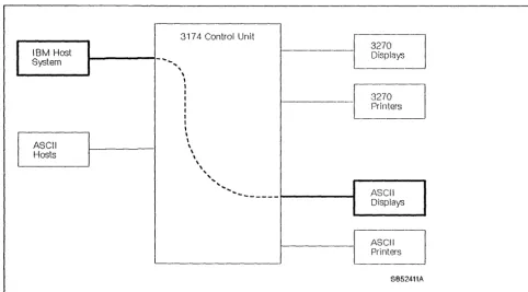
ASCII Subsystem Configurations
IBM Host System
ASCII Hosts
Figure 9 shows 3270 terminal emulation with ASCII terminals corrununicating with an IBM host. The ASCII display units and printers can be connected to the AEAs directly or with a cOlnmunications link and modems.
I - - - l - ....
..
3174 Control Unit
,
\,
I I I I I I II
,
,
\ \ \ \ \ , ''', ... ---~---~ 3270 Displays 3270 Printers ASCII Displays ASCII Printers S852411AFigure 9. 3270 Terminal Emulation. ASCII Terminals Communicating with an IBM I-lost.
Regardless of the method used to connect ASCII terminals to the AEA ports, the display screens appear just as they would on a 3270 terminal. This includes the operator information area at the bottom of the screen.
Note: Some ASCII terminals are capable of displaying only 24 lines. In order to display the 25th line (operator information line) on these tenninals, it tnust be requested by a key sequence.
[image:21.624.76.559.165.432.2]•
I
IBM Internal Use Only
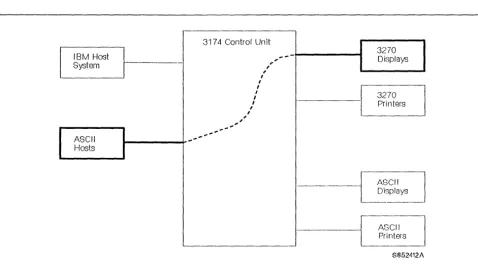
Figure 10 shows ASCII terminal emulation with 3270 display stations communi-cating with an ASCII host. The ASCII hosts can be connected to the AEAs directly or with a communications link and rTIodems.
31 74 Control Un it
3270
I
IBM Host ,
...
--
DisplaysSystem
,
,
,I I
,
I 3270
,
,
Printers,
,
,
,
,
, -,
ASCII ,
...
... , '
...
Hosts
- - - - . - - -
ASCIIJ
Displays
- - - ASCII
Printers
8852412/\
Figure 10. ASCII Terminal Emulation. IBM 3270 Terminals Communicating with an ASCII Host.
Regardless of the method used to connect the ASCII host to the AEA ports, the display screens appear just as they would on an ASCII terminal.
[image:22.623.55.534.103.369.2]IBM Internal Use Only
[IBM Hasl
System
ASCII Hosts
Figure 11 shows ASCII tenrunals communicating in ASCII passthrough mode with an ASCII host via AEAs. There is no protocol conversion; the 3174 merely passes the data between the ASCII host and the ASCII terminals.
317 4 Control Unit - - - ,
[image:23.623.74.559.90.371.2]" " " ' "
... "'-
...
---~---~
3270
Displays
3270
Printers
ASCII Displays
J - J l S C I l
'---_ _ _ _ _ _ _ _ - - - - ' 1 - - -
L
PrintersS052413A
Figure 11. ASCII Passthrough. ASCII Terminals Communicating with an ASCII Host.
The display screens at the ASCII terminals, of course, remain unchanged from normal.
IBM Internal Use Only
Host Attachment
ASCII host attachment is through any of the AEA ports. Links to ASCII hosts can carry only one session at a time; when all paths are in use, requests for sessions are not granted until a session ends and a path is available.
Default Destination: In general, a destination is a host to which a tenninal user has access. A default destination can be specified by customizing; the default destination is the host to which an ASCII terminal is connected when the user calls into an AEA port on the 3174. If a default destination is not specified, the user is presented at connection time with a Connection Menu that consists of a list of host destina-tions from which the user can select a particular host or application.
Connection Menu: Figure 12 shows the Connection Menu that lists all the host connections that can be accessed by the display unit user. Hosts are identified by customizing. The Connection Menu also provides host availability status informa-tion. If a path is available to that host, a connection will be made.
CONNECT! ON MENU of 1
---
---Enter a number (NUM) or a name on the Comnand Line, then press ENTER:
NUM NAME STATUS NUM NAME
1 VM SYS2 15
2 XY GRAPHICS 16
3 PARTS 17
4 18
5 19
6 20
7 21
8 22
9 23
HI 24
11 25
12 26
13 27
14 28
PF1= HELP 3= END PF7= BACK 8= FWD
===>TO:
Figure 12. Connection Menu. The selections that arc displayed on this menu are a result of AEA customizing.
[image:24.620.164.538.283.581.2]IBM Intcrnal Use Only
During customizing there are two options available when presenting the Connection Menu for selection.
1. The terminal user may be presented with the Connection Menu but is only allowed to select the default host assigned. See Figure 13.
- - - ,
3174 Control Unit
r---: Customizing •
1 - - - 1 Adapter • • - - - -...
---_-41
Adapter 1 - - - - 1S852414A '
-Figure 13. Conncction Menu Option 1
IBM Host
ASCII Host
ASCII Host
ASCII Host
2. The tenninal user may be presented the Connection Menu an be allowed to select anyone of the hosts from the list. See Figure 14.
3174 Control Unit
---Adapter Customizing
Adapter
...
...
j
.+C
Connection Menu.--
...---l~
_____
J
I•
AdapterS852415A
Figure 14. Connection Menu Option 2
[image:25.621.69.559.110.322.2] [image:25.621.73.553.387.635.2]IBM Internal Use Only
IBM Internal Use Only
Dual Control Units
No discussion of host attachment is complete without presenting the 7232 Dual Control Unit Terminal Multiplexer (see Figure 15).
The 7232 Dual Control Unit Terminal Multiplexer Model 00 1 (available with RPQ 8K1670) is an enhanced version of the 3299 Model 2 Terminal Multiplexer. It pro-vides 3299 Model 2 functions and, in addition, can be attached to two 3174 control units (any model). Attached CUT (control unit terminal) devices can then toggle-switch between the two 3174s. The two 3174s can be attached to two different hosts using the same or different protocols on the host links. Selection is under control of the operator using the change screen key, which is described in the next section, "Multiple Logical Tenninals."
3270 Host A 3270 Host B
o
o
0 0 0 0Hosts
Control Units
7232
Devices
S852406A
Figure 15. 7232 Connection Diagram. The 7232 allows any CUT device to connect to either of two 3174 Subsystem Control Units.
[image:27.621.76.553.263.590.2]IBM Internal Use Only
IBM Internal Use Only
Multiple Logical Terminals (ML T)
The 3174 ASCII subsystem is even further enhanced by the ML T function, avail-able with Release 3 microcode.
The ML T function allows the terminal user to interact with up to five host sessions from a 3270 CUT device. The host sessions are logical terminals (LT1 through LTS) that can be connected to a single IBM host, one or more ASCII host(s), or both. Access to these hosts is made through either the Connection Menu or the Default Destination Procedure, which is a function of customizing.
Note: MLT is not supported for ASCII terminals or 3270 DFT terminals.
Active and Background Sessions
The display screen shows one session at a time; any keys that are pressed are used by that session. This is called the active session. The other sessions are nlaintained in the 3174 Subsystem Control Unit and are called background sessions.
Change Screen Key
Different sessions that have been dermed for a terminal by customizing are accessed by using the change screen key. When this key sequence is used, the current active session is saved in the background and the next background session becOlnes the active session in a round-robin fashion. None of the background sessions are affected by anything that is entered during the active session. The change screen key varies with the keyboard type. On a base text QWERTY keyboard, press and hold AL T, then press P A2.
IBM Internal Use Only
Case
Study
While reading the following customizing scenario, refer to Figure 16.
ML T Customizing Scenario
IBM Host
I-:~-I
;7
=-fD~
~174
_ _ _ _ _ _! :
___
U
I Change / I ASCII H t
I Screen Key I os fl c=::::J )
(:JJJ
-!
Fun/Clion ,.,.
LT1
!
m
----1
Connection
---I LT2
.--+---
Menu 'I
I
ASCII Host3270 Terminal
cs
i
LT3·i---m _ _
i~l~
~I
l f 4 1~J
-
:
.,,~
I LTS. I ~
L ____
~
__
I~
g=L~]~
~
W~"1~~
__
j
,\SCII Host
Jj
ASCII Host
ASCII Host
S852407A
Figure 16. Multiple Logical Terminal Operation. Each activation of the change screen key selects LT1, L'1'2, LT3, L T4, and LT5 in sequence in round-rohin fashion.
[image:30.624.55.528.138.625.2]IBM Internal Use Only
The 3270 CUT device is customized for AEA with five logical terminals (LT 1 through L T5).
• LTI is customized to have the IBM host as the default destination.
• L T2 is customized to have the Connection Menu as the default destination. • LT3 is customized to have ASCII host 3 as the default destination.
• L T4 is customized to have ASCII host 4 as the default destination. • L T5 is customized to have ASCII host 5 as the default destination.
ML T Operation Scenario
The following scenario is depicted on Figure 16 on page 22 and takes you through a typical MLT operation from the power-on of the 3270 CUT device through the selection of different host sessions.
• When the operator powers on the 3270 device, the LT 1 display on the 3270 terminal is frmn IBM host session
m.
• When the operator presses the change screen key, the LT2 display on the 3270 terminal is the Connection Menu.
The operator selects III M host session
111
from the Menu list.The operator performs some transactions using session
111,
then tenninates the session.• The 3270 terminal display is again the Connection Menu for L T2. The operator selects ASCII host session
B
from the menu list.The operator performs some transactions using host session
m,
then ter-minates the session.• The 3270 terrrlinal display is again the Connection Menu for L T2. The operator selects ASCII host session
m
from the Inenu list.The operator perform some transactions using host session
m
and termi-nates the session.• When the Connection Menu for LT2 returns to the screen, the operator presses the change screen key and the LT3 display on the 3270 terminal is ASCII host session
0
on ASCII host 3.• lbe operator presses the change screen key and the LT4 display on the 3270 terminal is ASCII host session
D
on ASCII host 4.- The operator perfonns some transactions on host session
0,
then tenni-nates the session.• The operator presses the change screen key and the L T5 display on the 3270 terminal is ASCII host session
m
on ASCII host 5.Note: If the operator continues to press the change screen key, the round-robin sequence of LTl, LT2, LT3, LT4, LT5, LTl, etc. is repeated.
By using the AEA feature, the MLT function, and tieing it all together with special customizing, you can see that the customer has considerable terminal/host
connectivity beyond what has been previously available.
IBM Internal Use Only
IBM Internal Use Only
Customizing
Customizing for 3174, as you know from the 3174 base course (75021), is a cus-tomer responsibility. Por the ABA feature, the cuscus-tomer is required to define the:
• Connection type
• Operational characteristics of the equipment installed • Physical equipment path
• Logical path.
Once the physical and logical paths have been identified, the customer is required to smrunarize the information into sets for entrv into the AEA customizing panels.
Stations and Sets
Station Set
I
IBM Host StationThe term station is used in the customizing procedures to differentiate between the traditional 3270 operation and the additional access provided by the AEA feature. A station may be either an:
• IBM or ASCII host • 3270 or ASCII display unit • 3270 or ASCII printer.
Many of the stations have the same characteristics. Therefore, provisions have been made for entering and storing station common information as a station set, thus eliminating the need to enter the same information many times (see Pigure 17).
--3174 Control Unit
~er
1
Adapter Station Set
--, 3270 Display Station
I
. - - - ---, 3270 Display Station
I
~- {E70 Display Statio~
'
-S852416A
Figure 17. Host Set and Terminal Set
[image:33.615.79.565.420.663.2]IBM Internal Use Only
Port Type and Port Sets
The port type is used to identify the physical connection to the 3270 terminal adapter and the AEAs. The 3270 terminal adapter ports accept the traditional coaxial type cables used to connect 3270 type terminals. The AEA ports accept the cables used to connect direct, nonswitched, and switched comlllunication links.
Many of the port types (direct, nonswitched, switched) may be the same for a given station set. Provisions have been made to group these ports into port sets as shown in Figure 18.
3174 Control Unit
Port Sets Adapter
PN Port Type
•
0 Switched•
1 Switched•
2 Switched•
3 Switohed•
4 SwitchedI
7 Non-Switched
~~
Figure 18. Port Sets
26
IUM 3174 Asynchronous Emulation Adapter FeatureStation Sets
,
,
,
,
~ ASCII r::~Play~/
,
,
,
I 0SC11O~rJ,
,
,
0SCI~DisplayJ
,
r---,
,
,
- - - 1
,
,
,
,
,
f!iSC!
I PrinterI :
I I
_______________ J
[image:34.617.51.531.201.495.2]IBM Internal Usc Only
Port sets may be used by more than one display station set, provided that the station types of the station sets are different. The different station types are needed to enSllre that the control unit can determine to which station set a connection should be made when both station sets have the satne port type (see Figure 19).
3174 Control Unit
Port Set Adapter
PN Port Type
4 Switched
L
5 Switchecj6 Switched
l
/
Figure 19. Connected Terminal and Port Sets
I 1 I I I I I I I I ~
Station Sets
---,
L
ASCII VT100 DiSPI~ { ASCII VT100 Di~---~ I I I I I I I I I I OBM _ - _ _ 3101 0 _ _ _ _ _ DiSP~ - : I
I
CJ.:@0
3103 DiSplay] : IS852417A
[image:35.617.80.566.109.361.2]IBM Internal Use Only
Customizing Screen Changes
You should be familiar with some of the customizing process and some of the cus-tomizing screens from the base course. This portion points out how AEA affects those screens with which you are already familiar.
Customize Control Diskette Menu: Figure 20 shows the Customize Control Diskette Menu screen. Notice that option 5, AEA Configure, has been added to the menu. Selecting this option presents the customer with a number of panels with responses to questions that describe the configuration of hardware and software for both 3270 and ASCII devices.
_ _ _ _ _ Customize Control Diskette Menu _ _ _ _ _ _ Select option; press ENTER
Option Description 1 Configure 2 Define PAM 3 Merge RPQs 4 Modify Keyboards 5 AEA Configure
Select ===>
PF: 3=Quit 12=File
Figure 20. Customize Control Diskette Menu. The addition of Option 5 allows the cus-tomer to configure for the AEA feature.
Figure 21 on page 29 shows the Local (SNA) attaclunent screen. Notice that the host attachment panel for Local (SNA) has Questions 110 and 178 added. Question 110 is for the MLT level in order to reserve the appropriate amount of 3174 storage depending on the amount of ML T functional support the custOIner desires. Ques-tion 178 is for the customizing of 7232 Dual Control Unit Terminal Multiplexer switching.
These additions also apply to the other host attachment panels [Local (Non-SNA), SDLC, etc.] as well.
[image:36.617.156.534.211.457.2]IBM Internal Use Only
_ _ _ _ _ Local (SNA)
1(;)4 - XX 188 - 8888888 118 - 8 116 - 8
121 - 81 125 - 88888888 127 - 8 0
132 - 8 808 136 - 888 8 137 - 8 8 8 8 138 - 0
141 - A 165 - 8 166 - A
173 - 88888888 175 - 888888 178 - 8 213 - 1 215 - 88888 228 - 8
222 - 8 223 - 18 224 - 2 225 - 4
Figure 21. Host Attachment. Questions 110 and 178 have been added.
Figure 22 on page 30 depicts the port assigmnent customizing panel. Notice that eight port assignments each have been added for hardware groups 21, 22, and 23, corresponding to the maximum of three AEAs. This is where the customer assigns the primary decimal addresses to the AEA ports.
[image:37.621.178.565.60.282.2]IBM Internal Use Only
_ _ _ _ _ _ 117: Port Assi·gnment _ _ _ _ _ _
LT=888 C@ 26-88 26-82 26-04 26-06 26-88 26-18, 26-12 26-14 26-16 26-18 26-28 26-22 26-24 26-26 26-28 26-38 21-80 21-02 21-84 21-86 22-88 22-82 22-84 22-06 23-88 23-82 23-84 23-06
#15 LT1 LT2 LT3 LT4 LT5 P 51 52 S3 54
C@ 26-81 26-02 26-05 26-87 26-09 26-11 26-13 26-15 26-17 26-19 26-21 26-23 26-25 26-27 26-29 26-31 21-01 21-83 21-05 21-07 22-01 22-03 22-05 22-07 23-81 23-03 23-05 23-07
116=n CCjMMMjH05T #IS LT1 LT2 LT3 LT4 LT5
P 51 52 53 54
Figure 22. Port Assignment. Port assignments for a maximum of three AEAs have been added.
The top portion of Figure 23 on page 31 shows where the custOIller defmes printers that are to be used for copy operations. The custOlner can now also defme AEA attached printers for local, shared, or system printing. This is done by entering the appropriate hardware group (21, 22, or 23) and port number for each of the printer defmition entries.
Refer to the lower right portion of Figure 23 on page 31. Notice that the customer can define AEA attached displays that are authorized to use printers that have been defined in the top portion. This is done by defining the displays for hardware groups 21, 22, and 23.
[image:38.620.150.531.59.471.2]IBM Internal Use Only
Entry
2 3 4 5
_ _ _ _ PAM Definition _ _ _ _
Printer Port
Mode
TA Display Port
Class
7 8
01234 56789 01234
AEA Display Port
Entry 26 26 21 22 23
o
1 1 3 0 0 001234 56789 01234 56789 01234 56789 01 01234567 01234567 01234567
1
2
.
.
3
.
...
.
4
.. .
..
.
5
. .
Figure 23. Printer Authorization Matrix (PAM). ASCII printers may be defined by speci-fying the appropriate AEA hardware group and port number in the upper portion. Authorized ASCII db;plays may be defined by specifying the appro-priate A EA hardware group and port number for the matching entry in the lower portion.
Por an example of how an ASCII display can be authorized to use a 3270 printer for local copy operations, refer to figure 24 on page 32.
• The customer defined an IBM 3287 Terminal Adapter attached printer (hard-ware group 26), port 2 for local copy. This was done by completing printer definition Entry 1.
• The customer defined an AEA attached ASCII display on port 3 of the first AEA (hardware group 21) in display definition Entry 1.
In tIlls example, the ASCII display on port 3 of the first AEA is authorized to use the Terminal Adapter attached printer (IBM 3287) on port 2 for local copy (printing) operations.
[image:39.624.188.567.58.381.2]Entry
2 3 4 5
IBM Internal Use Only
PAM Defi nit i 011
---
---Printer
Port
26 - 82
Mode
TA Display Port
Class
7 8
81234 56789 81234
AEA Display Port
Entry 26 26 21 22 23
2
3
4 5
8 3 0 0 8 81234 56789 81234 56789 01234 56789 81 81234567 01234567 01234567
.x.
Figure 24. Completed Printer Authorization Matrix (PAM). The IBM 3287 Printer attached to the T A hardware group 26, port 2 is defined for local copy in Entry
J. The ASCII display on AEA, hardware group 2] , port 3 is authorized to use this printer for local copy operations.
[image:40.623.154.530.56.373.2]IBM Internal Use Only
Problem Determination Assistance
Customizing for the AEA feature and the MLT function is more complex than that on a basic machine. Therefore, it is the intent of tills portion to clarify the role of customizing problem determination assistance to the customer.
Customizing Problems: You have just looked at a few of the areas of customizing that have changed as a result of the AEA feature and the MLT function. There is also additional AEA customizing that requires special training and is not covered in this TAl document.
When you are servicing the 3174 and you suspect that the problem is caused by a customizing error that you cannot recognize, the IBM SE has special training and should be contacted for further problem determination assistance.
IBM Internal Use Only
IBM Internal Use Only
Maintenance Package Updates
New MAPs
The maintenance approach to the 3174 with AEA feature remains unchanged. However, the maintenance package has been updated to accommodate the AEA feature.
The following new MAPs have been added to the MIM for troubleshooting AEA problems:
• ASCII Problelll Entry
• Direct Connection Port(s)-any failure • Leased Connection Port(s)-any failure • Switched Connection Port(s)-any failure.
New Status Codes
New Tests
Offline Tests
New status codes have been added to the Status Code Chart in the MIM that are associated with the AEA feature.
New omine and online tests have been added to diagnose problems associated with the AEA feature. As previously, you are directed by the MAPs and procedures in the MIM when to run the appropriate testes).
The basic Asynchronous Emulation Adapter omine tests are hardware groups 21, 22, or 23, corresponding to the three AEAs that are available on the floor models. Note: Only hardware group 21 is available on the 51R and 52R models.
The optional AEA omine test provides an ABA port driver/receiver wrap test on any of the eight AEA ports. The test is initiated by specifying the hardware group (21, 22, or 23), a function number (FN) of 01, and a function parameter (FP) of 00 through 07. This test does not require a wrap plug to be installed.
Online Tests
IBM Internal Use Only
Figure 25 shows the Test 12 Menu screen. Test 12 has been added to provide an access to testing for an AEA terminal, port, or programmable I modetn. It also
pro-vides a status summary and capability to reset error counters on any or all AEAs. The options are:
1 -AEA port test menu 2 -Display status summary
3 -Reset line errors on all AEA HGs 3,0 -Reset line errors on HG n
Option 1 2 3 3,n Note:
_ _ _ Asynchronous Emulation Adapter Tests _ _ _ Description
AEA port test menu Di sp 1 ay status sUn1nary
Reset line errors on all AEA HGs Reset line errors on all HG (n=21-23)
- Option 1 exits from 3174 TEST mode
To go directly to other tests, enter: /Test,option Select option; press ENTER ===>
PF: 3=Quit 12=Test menu
Figure 25. Main Menu for Test 12
Figure 26 on page 38 shows the Asynchronous Emulation Adapter Port Tests menu.
• Option 1: Provides a facility to test a stnart modetn through its asynchronous emulation adapter port, provided that port is not presently in session. Access and manipulation of the modem, using that modem's command syntax, enables the following:
Modem and Customizing Test
This function provides access to internal diagnostic and customizing proce-dures built into certain smart modems. There are two reasons why this function is important:
1. By running diagnostics internal to the modem, you are able to isolate a probletn to the asynchronous communication equipment on a specific port, provided proper operation of the asynchronous emulation adapter port has already been verified.
2. By customizing the modem to certain specifications, you can ensure proper operation or verify whether or not the modem has been custom-ized correctly for normal operations.
Modem Dial-Out Function
This function enables you to test the dial-out capability of the modem. By providing a number of a phone close by or the nurnber of an actual ASCII dial-in port to the modem, you can verify proper operation of the modem.
[image:44.620.154.536.121.404.2]IBM Internal Use Only
• Option 2: Provides access to an asynchronous emulation adapter port not pres-ently in session. This access allows you to perform a wrap test on the asyn-chronous emulation adapter port.
Note: The asynchronous emulation adapter wrap plug (P/N 61X4602) must be installed on the port connector before invoking the wrap test.
If a tnodem cable is attached to the port being tested, you can also test it by installing the wrap plug at the modem end providing that the modem end con-nector is male/female compatible with the wrap plug.
• Option 3: Provides a means of verifying an ASCII tenninal's ability to receive data correctly. From the invoking terminal, you can send data through the asynchronous emulation adapter port connector to a terminal not presently in session. This test verifies the data path and operation of the terminal receiving the data.
The override settings are indicated by WXYYZZ,
where:
W = Line Speed X = Parity
Y
=
Flow Control Z=
Stop Bits. Notes:1. If you enter override settings, you may need to change the parameters on the ASCII device(s) you are testing.
2. The actual WXYYZZ values are given in a table in the MIM and you are directed by the MAPs when to enter them.
These parameters are used by the control unit to comtnunicate with ASCII devices. They are entered during customizing and tlus test allows you to temporarily change them without changing the actual customizing.
IBM Internal Use Only
_ _ _ Asynchronous Emulation Adapter Port Tests _ _ _ _ Option
1,PN,HG 2,PN,HG 3,PN,HG 3,PN,HG,WXYYZZ
Description
Connect to smart modem AEA port wrap
Transmit data (default settings)
Transn~t data (override settings)
PN=Port Number (0-7) HG=Hardware Group (21-23) WXYYZZ=Override port and station descriptor values Select option; press ENTER ===>
PF: 3=Quit 12=Disconnect
Figure 26. Asynchronous Emulation Adapter Port Tests Menu for Test 12. This menu is used to test programmable) modems, wrap t.est AEA ports, and verify ASCII data path with default and override customizing port and station descriptor values.
[image:46.623.155.538.60.260.2]IBM Internal Use Only
Major Changes
Some of the existing online test screens with which you are already familiar have been changed with the availability of the ABA feature and Release 3 microcode.
Logs Menu for Test 1: Figure 27 shows the Logs Menu screen for Test 1. Notice that Option 4 has been changed. All errors in the event log for the port number on a specific hardware group will display when you enter 4,n,m
where:
n is a specific port number from 0 through 31 m is a specific hardware group from 0 through 99.
For exatnple, if you enter 4,5,21, all the errors in the event log for port number 5 of the AEA in hardware group 21 (f1[st AEA) will be displayed.
Notice that Option 7 has been added. Entering 7 (Change log mode) changes the log mode from Normal to Intensive or vice versa. The current log mode is noted on the Logs Menu screen for Test 1. Normal mode is regularly used for logging errors. Intensive rnode was created to record those high frequency loggable errors that are not recorded in Normal mode. Because of the high frequency of errors, Intensive mode should only be used when needed. To guard against continued use, the control unit changes the log mode back to Normal when a 76-hour timer expires.
Option 1 2 3,n 4,n 4,n,m 5,xxxx 6,n 7
Logs Menu Description
Response time log All events logged Hardware group (n=0-99) Port n (n=0-31)
Port n,hardware group m (n=0-31,m=0-99) Status code (replace x's with search digits) Logical terminal (n=0-254)
Change log mode (normal/intensive)
To go directly to other tests, enter: /Test,option Select option; press ENTER ===>
PF: 3=Quit 12=Test menu
Figure 27. Logs Menu for Test 1. Option 4 has been modified to allow searching for port logs on the AEA hardware groups as well as the T A hardware group. Option 7 has been added to allow toggle switching of the log mode between normal and intensive modes.
[image:47.623.184.565.349.599.2]IBM Internal Use Only
Pigure 28 shows the screen, "Log Records - AU." Notice the PHG (Primary Hard-ware Group) and CIIG (Connection HardHard-ware Group), which are the hardHard-ware groups associated with the error. The PHG field contains 00 or 99 if the error is not associated with a particular hardware group, or if the hardware group cannot be identified. 00 or 99 are not displayed in the enG field.
For example, a 3270 terminal that is experiencing errors during an ASCII host session would have 26 in the PHG field and 21, 22, or 23 in the CHG field.
_ _ Log Records - All
(Day/Time since last POR: 000/08:11)
Day Time SC QA PHG_PN CHG PN LT Extended data bytes (B1-B6)
000 08:11 0315 58 16 000 00:03 0500 01 16 000 00:02 0503 01 16 000 00:02 3174 01 00 015 21:48 0402 02 16 015 21:22 0401 03 16 015 21:20 0209 51 26 015 21:19 0201 51 26 015 21:07 3174 01 00 015 20:01 0311 01 87
26 02 26 06 16 16
B1 B3 B5 B7 B9 B11 B13 B15 9210 1100 01XX XXXX XXXX XXXX XXXX XXXX
002 0000 0003 F350 0000 006 0001 0004 3C40 4000 008
008
9052 1900
SC=Status Code QA=Qualifier HG=Hardware Group PN=Port number LT=Logical terminal PHG_PN=PrimaryHG_PN CHG_PN=ConnectionHG_PN
To go directly to other tests, enter: /Test,Option Select test; press ENTER ===>
PF: 3=Quit 8=Fwd 12=Test menu
Figure 28. Log Record Display Panel for Test 1. IIG (hardware group) has been modi-fied to PIIG _PN (primary hardware group-port number) and CI-IG _PN (con-nection hardware group-port number) has been added.
Figure 29 on page 41 depicts the hardware configuration table screen. Notice that the AEA adapters and associated cable assemblies are listed and identified by hard-ware group, FR U type, and location in the 3174.
[image:48.621.156.535.164.448.2]IBM Internal Use Only
Hardware Configuration Table
HG TYPE LC DESCRIPTION
88 9881 88 Invalid Card/Cond 81 9154 21 File Adpt
SC
81 9118 81 Diskette Drive 32XY 81 9118 82 Diskette Drive 2
88 9588 18 Timer
89 9818 85 Ops Panel Adpt 89 9521 86 Ops Panel Assembly 11 9253 22 Type 1 Com Adpt-XXX 11 9273 22 Type 2 Com Adpt-XXX 16 9218 11 Channel Adpt 16 9238 18 Channel Drv/Recvr 21 9333 14 Async Ernul Adpt 21 9548 61 AEA Cable Assembly 22 9333 13 Async Ernul Adpt
Select Test; press ENTER ===>
PF: 3=Quit 12=Test Menu
HG TYPE LC DESCRIPTION
22 9548 62 AEA Cable Assembly 23 9333 12 Async Emul Adpt 23 9548 63 AEA Cable Assembly 26 9154 21 Terminal Adapter 26 9172 15 Term Mpx Adpt 88-07 26 9172 16 Term Mpx Adpt 88-15 26 9172 11 Term Mpx Adpt 16-23 26 9172 12 Term Mpx Adpt 24-31 31 9350 Token-ring Adpt 46 9830 25 Ene/Decrypt Adpt 87 9851 19 Storage 512K 87 9851 28 Storage 512K 87 9852 Storage IMEG
SC
Figure 29. Hardware Configuration Table for Test 2. This table shows the maximum con-figuration for Models 1 L, 1 R, 2R, and 3R. Only those FRUs that are phys-ically installed are displayed in this table. A I-Mb base storage is available. Eithcr two 512 K-byte cards are installed or one I-Mh card. Up to 3-Mb of storage can be installed.
XXX indicates tilC type of cable or wrap plug inst.alled.
[image:49.618.180.562.61.328.2]IBM Internal Use Only
Figure 30 shows the status summary screen. There are a few changes to the Test 3 display. They are described in detail in the 3174 MIM and a brief description is given here:
• Attach: An uppercase M in this line represents a tenninal that is attached to a controller through a 7232 Dual Control Unit Terminal Multiplexer.
• Status: A lowercase s in this line indicates that the terminal is presently COIn-municating with another controller through a 7232 Dual Control Unit Terminal Multiplexer or, in other words, is in the switched state.
• II os(: This line has been added and represents the type of host to which the terminal is currently connected or if no host is configured. Por MLT ports, a blank, a 3, or an A represent the foreground session only.
Blank
x
3 A
No current host
No host sessions configured IBM host connection established ASCII host connection established.
Status Sumnary - HG 26
Port Address Attach Status Terminal Cable Cable Max Host
88 82 84 86 88 18 12 14 16 18 28 22 24 26 28 38 81 83 85 87 89 11 13 15 17 19 21 23 25 27 29 31
mmmmmmmmd xMMMMMMMmmmmmmmm
111 188 1 8 1 8 8 8 8 8 8 8 8 - - 1 8 s 1 181 8 8 1 881 v v v v v v v p p p v v v v v v v v v v v
LU
d direct
3 3 3 A
+ + +
m = multiplexer
1 = on
o
= offConnection number:
* : ..
3 A 3 + +I .
: *
3 3 x x 3
+ +
off (error) i = OFT device x = unconfigured ? = unknown
p = printer + = in session
v = video display 3=3270 A=ASCII Outgoing call 914-555-1234
To go directly to other tests, enter: jTest,Option Select Test; press ENTER ===>
PF: 2=Quit 12=Test Menu
3
+
*
8 errors = 1-5 err = 6-15 err
*
= > 15 errFigure 30. Status Summary for Test 3. The Attach and Status lines have been changed. The Host line has been added.
[image:50.618.160.540.105.540.2]113M Internal Usc Only
Figure 31 is the Display Control Blocks Menu and shows that Option 2 also allows you to specify one of the AEA hardware groups as well as the TA hardware group. The bit definitions for the displayed port control blocks are given in the MIM.
Option
1, n 2
2,n,m
3
_____ Display Control Blocks Menu
Description
Register page n (n=0-3F)
Port control area (Requester's Port)
Port n control area on HG m (n=031 m=21-23,26) X.21 SHM / X.25 Host Control Data
To go directly to other tests, enter: /Test,Option Select option; press ENTER ===>
PF: 3=Quit 12=Test Menu
Figure 31. Display Control mocks Menu for Test 6. Option 2 has been modified to also allow the display of port control blocks for the AEA hardware groups.
[image:51.620.187.568.105.294.2]IBM Internal Use Only
IBM Internal Use Only
Teleprocessing Network Support
With the availability of the AEA feature, you can see that te1ecOJnmunications network problem determination may become more complex. The maintenance package directs you, through MAPs and procedures in the MIM, to run the appro-priate testes) to do initial AEA telecOInmunications network problem determination.
When you suspect that there is an AEA network problem that you cannot solve using the maintenance package, specialized IBM support is available. It is called the 113M Network Support Center, located in Atlanta. The Network Support Center is staffed by personnel with specialized telecOInmunications network training. They normally work with customers and CEs to solve tclecomtnunications network prob-lems and can be reached by calling any of the following nUlnbers:
W A TS 1- 800-426- 2472 Tie Line 596- 5070 Outside IBM (404)-984-5070
IBM Internal Use Only
IBM Internal Use Only
Summary
You should now have an overall understanding of the additional connectivity avail-able to the customer afforded by the AEA feature, Multiple Logical Terminals func-tion, and the 7232 Dual Control Unit Terminal Multiplexer. More detailed
descriptions are contained in the documents listed under "Related Publications" on page IV.
Although the subsystem configurations can be considerably tnore complex than in the past, the Inaintenance approach remains unchanged; it is directed by MAPs and procedures in the MIM. When you cannot :mlve a problem using the maintenance package, specialized support is available; the IBM SE for custOlnizing problems and the Network Support Center for telecommunications problems.
This concludes the technical awareness infonnation for the 3174 Asynchronous Emulation Adapter. It is a good time to review any areas where you feel you need a better understanding.
IBM Int.ernal Use Only
IBM Internal Use Only
List of Abbreviations
This list defines important or unique abbreviations used in this course. If you feel that an abbreviation should be added to the list, please send a comment to the author or use the Reader's Comment Form at the back of this book. AEA ASCII CE CHG CUT DFT EBCDIC EIA FN FP FRU IIG
ASCII Emulation Adapter
American National Standard Code for Information Interchange
Customer Engineer
Connection Hardware Group Control Unit Terminal Distributed Function Terminal Extended Binary-Coded Decimal Inter-change Code
Electronic Industries Association Function Number
Function Parameter Field Replaceable Unit Hardware Group I/O LT Mb MAP MIM MLT PIN PAM PIIG PN RPQ SDLC SE SNA TA TAl TMA Input/Output Logical Terminal Megabyte
Maintenance Analysis Procedure Maintenance Information Manual Multiple Logical Terminals Part Number
Printer Authorization Matrix Primary Hardware Group Port Number
Request for Price Quotation Synchronous Data Link Control Systems Engineer
Systems Network Architecture Terminal Adapter
Technical Awareness Information Terminal MUltiplexer Adapter
113M Internal Use Only
IBM Internal Use Only
Glossary
This glossary defines important or unique terms as they are used in this course. If you do not find the term you are looking for, refer to the index or to the book Vocab-ulary for Data Processing, Telecommunications, and Office Systems, GC20-1699.
If you feel that a term should be added to the list, please send a comment to the author or use the Reader's Comment Form at the back of this book.
Asynchronous Transmission. Transmission in which each character is individually synchronized (usually by the use of start elements and stop elements) This is in contrast to synchronous transmissions such as Bisyn-chronous (Bisync) and SLDC (Synchronowl Data Link
Control) which depend upon the receiving station being synchronized with the transmitting station in order for the receiving station to decode the data being trans-mitted.
ASCII. American National Standard Code for Informa-tion Interchange. The standard code, using a coded character seL consisting of 7 -bit coded characters (8 bits including parity check), used for information interchange among data processing systems, data communications systems, and associated equipment. The ASCII set con-sists of control characters and graphic characters. ASCII Host. The processor, running an application program or programs, that communicates with terminals using ASCII protocol.
ASCII Terminal. A display or printer that communi-cates with its host using ASCII protocol.
Changc sercen ){cy. A 3270 display terminal key used to select host sessions with the Multiple Logical Terminal (MLT) function and 1.0 switch between each of two 3174 control ulliL~ wiLh a 7232 Dual Control Unit Terminal Multiplexer. On a base QWERTY keyboard, the change screen key function is invoked by pressing and holding the ALT key and then, pressing the PA2 key. EBCDIC. A set of 256 characters, each represented by eight bits.
Modem. (modulat.or-demodulator) A device that modu-lates and demodumodu-lates signals transmitted over data communication facilities. One of the functions of a modem is to enable digital dat.a to be t.ransmitted over analog t.ransmission facilities. See also smart modem. Protocol. (1) A specification for the format and relative timing of information exchanged between communi-cating part.ies. (2) The set of rules governing the opera-t.ion of functional units of a cornmunications system that must. be followed if communication is to be achieved. Q\VERTY Keyboard. A 3270 terminal keyboard in which the first six alphabetic characters on the second row from the top are QWERTY.
Smart Modem. A modem that is capable of responding to remotely originated test and customizing commands. 3270 Host. The processor, running an application program or programs, that communicates with terminals using 3270 protocol.
3270 Terminal. A display or printer that communicates with it.s host using 3270 protocol.
IBM Internal Use Only
IBM Internal Use Only
Index
A
active sessions 21 AEA feature 3 AEA port wrap 37 all logs 40
analysis procedure, maintenance (MAP) 35 ASCII data path test 37
ASCII passthrough 11 ASCII printers 2 ASCII protocol 2
ASCII subsystem configurations 13 communications link 13 modems 13
ASCII terminal emulation 11 assignment, port 29
assistance, problem determination 33 asynchronous emulation adapter hardware 3
B
background sessions 21
C
case study, MLT 22
customizing scenario, ML T 22 ML T customizing scenario 22 ML T operation scenario 23 operation scenario, ML T 23 scenario, ML T customizing 22 scenario, MLT operation 23 change log mode 39
change screen key 19, 21 communications link 13
communications links, hardware 6 connection menu 16, 21
control diskette menu, customize 28 copy, local 31
customize control diskette menu 28 customizing 25, 28, 29
customizing override 37 customizing problems 33
IBM systems engineer 33 customizing test, smart modem 36
D
data path test, ASCII 37 DEC VT100 11
default destination 16 destination 16 destination, default 16 diskette menu, control 28 diskette menu, customize 28 display control blocks menu 43 dual control units 19
F
flow control 37
G
general information iii
H
hardware 3
hardware configuration table 40 hardware group, connection 40 hardware group, primary 40 hardware, communications links 6
connectivity 10 major functions 11
I
instructions ttl
intensive log mode 39 introduction 1
K
ASCII device ASCII host 1 IBM host 1
multiple logical terminal
key, change screen 19, 21
L
line speed 37 local copy 31 local printing 31 localfSNA 28 log mode, change 39 logs menu 39
M
maintenance analysis procedure (MAP) major changes 39
MAP (maintenance analysis procedure) materials 111
matrix, printer authorization (PAM) 30 menu,connection 21
menu, customize control diskette 28 microcode, release 3 21
MLT (multiple logical terminals) 21 MLT operation 22
modem 36
modem customizing test 36 modem test 36
modems ]3
35 35
multiple logical terminals (MLT) 21
multiplexer, 7232 dual control unit terminal 19
N
network problem determination 45 network support center 45
network support, telecommunications 45 normal log mode 39
o
omine tests 35 online tests 36
test] 2, using 36 override settings 37
P
PAM (printer authorization matrix) 30, 31 parameters, customizing override 37 parity 37
port assignment 29 port wrap, AEA 37 prerequisites HI
primary hardware group 40
printer authorization matrix (PAM) 30, 31 prin ting, local 3]
problem determination assistance 33 cllstomizing prohlems 33
protocol conversion 15 protocol conversion path 11 protocol, ASCII 2
protocol, 3270 2
54
IBM 3174 Asynchronous Emulation Adapter FeatureR
related puhlications iv release 3 microcode 21 round-robin fashion 23
S
screen, change key 19 SE (systems engineer) 33 sessions, active 21 sessions, background 21
IBM Internal Use Only
settings, customizing override 37 smart modem 36
smart modem customizing test 36 smart modem test 36
stat.us codes 35 status summary 42 stop bits 37 summary 47
support, tc/ecommunications nclwork 45 systems engineer (SE) 33
T
1'A I description III
telecommunications network support 45 terminology 1
test 1, using 39 t.est 12, using 36 test 2, using 40 test 3, using 42 test 6, using 43 test, smart modem 36
test, smart modem customizing 36 tests 35
omine tests 35 online tests 36
Numerics
3270 protocol 23270 terminal emulation 11
IBM Internal Use Only
IBM 3174 Asynchronous Emulation Adapter I'eature Technical Awareness Information
TAl 40600
ZZ25-8524-00
READER'S COMMENT FORM
You may use this form to communicate your comments about this publication, its organization, or subject, with the understanding that IBM may use or distribute whatever information you supply in any way it believes appropriate without incurring any obligation to you. Your comments will be sent to the author's department for whatever review and action, if any, are deemed appropriate.
Note: Copies of IBM publications are not stocked at the location to which this form is addressed. Please direct any requests for copies of publications, or for assistance in using your IBM system, to your IBM representative or to the IBM branch office serving your locality.
Possible topics for comment are clarity, accuracy, completeness, organization, coding, retrieval, and legibility.
If you wish a reply, give your name, company, mailing address, and date.
IBM Internal Use Only
ZZ25-8524-0
READER'S COMMENT FORM
- - -
-- -- -- --
-
-:: - -:E§~§:®
Please Do Not Staple
International Business Machines Corporation Department H70/Building 947
PO Box 390
Poughkeepsie, NY 12602
Please Do Not Staple