- - - -
- - - -
-
'-
-
--
--
-
---
_._----
---_
.
-
3270 Information
Display System
3174 Subsystem
Control Unit
Asynchronous Emulation Adapter
---
- - -
-
-
-
-
- - -----
-
----
--- --- --- , ---
3270 Information
Display System
3174 Subsystem
Control Unit
Asynchronous Emulation Adapter
Introduction
GA23-0331-1
File Number
Federal Communications Commission (FCC) Statement
Warning: This equipment generates, uses, and can radiate radio frequency energy and if not installed and used in accordance with the instructions manual, may cause interference to radio communications. It has been tested and found to comply with the limits for a Class A computing device pursuant to Subpart J of Part 15 of FCC Rules, which are deSigned to provide reasonable protection against such interference when operated in a commercial environment. Operation of this equipment in a residential area is likely to cause interference in which case the user at his own expense will be required to take whatever measures may be required to correct the interference.
Instructions to User: Properly shielded and grounded cables and connectors must be used for connection to peripherals in order to meet FCC emission limits. Proper cables are available from IBM authorized dealers. IBM is not responsible for any radio or television interference caused by using other than recom-mended cables or by unauthorized modifications to this equipment. It is the responsibility of the user to correct such interference.
Second Edition (October 1988)
Changes are made periodically to the information herein and are indicated by a vertical line to the left of the change. Before using this publication in connection with the operation of IBM systems or equipment, consult your IBM sales representative or the latest IBM System/370, 30xx, and 4300 Processors
Bibli-ography, GC20-0001, for the editions that are applicable and current.
References in this publication to IBM products, programs, or services do not imply that IBM intends to make these available in all countries in which IBM operates. Any reference to an IBM licensed program in this publication is not intended to state or imply that only IBM's licensed program may be used. Any func-tionally equivalent program may be used instead.
Publications are not stocked at the address given below. Requests for IBM publications should be made to your IBM representative or to the IBM branch office serving your locality.
A form for reader's comments is provided at the back of this publication. If the form has been removed, address additional comments to IBM Corporation, Department E02, P.O. Box 12195, Research Triangle Park, N.C., U.S.A. 27709-9990. IBM may use or distribute whatever information you supply in any way it believes appropriate without incurring any obligation to you.
Choosing the Right Book from the 3174 Library
The 3174 library contains information for installing, customizing, operating, main-taining, and programming the data stream for the 3174 control unit. The list below shows the manuals you need to perform these tasks.
To Organize Library Materials:
Binders and Inserts, SBOF-0089 Binder, SX23-0331
Inserts, SX23-0332
To Become Familiar with the 3174:
Master Index, GC30-3515
3270 Information Display System Introduction, GA27-2739
To Prepare Your Site for the 3174:
Site Planning, GA23-0213
Physical Planning Template, GX27-2999
To Set Up and Operate the 3174:
Models 1L, 1R, 2R, and 3R User's Guide, GA23-0337 Models 51 R, 52R, and 53R User's Guide, GA23-0333 Models 81R and 82R User's Guide, GA23-0313
To Plan for and Customize the 3174:
Customizing Guide, GA23-0214
Central Site Customizing User's Guide, GA23-0342
To Install Features or Convert Models on the 3174:
Encrypt/Decrypt Adapter Customer Installation and Removal Instructions,
GA23-0262
Fixed Disk and Diskette Drive Customer Installation and Removal Instructions,
GA23-0263
Terminal Multiplexer Adapter Customer Installation and Removal Instructions,
GA23-0265
Model Conversion Customer Setup Instructions; GA23-0295
IBM Token-Ring Network 3270 Gateway Customer Installation and Removal Instructions, GA23-0329
Storage Expansion Feature Customer Installation and Removal Instructions,
GA23-0330
Communications Adapter Customer Installation and Removal Instructions,
GA27-3830
Asynchronous Emulation Adapter Customer Installation and Removal Instructions, G A 2 3 - 0 3 4 1 '
To Plan for and Use the Asynchronous Emulation Adapter Feature:
Asynchronous Emulation Adapter Introduction, GA23-0331
Terminal User's Reference for Expanded Functions, GA23-0332
To Use the MuHlple Logical Terminals Function:
Terminal User's Reference for Expanded Functions, GA23-0332
Customizing Guide, GA23-0214
To Perform Problem Determination:
Customer Extended Problem Determination, GA23-0217
Status Codes, GA27 -3832
To Obtain Data Stream Programming and Reference Information:
Functional Description, GA23-0218
Data Stream Programmer's Reference, GA23-0059
Character Set Reference, GA27-2837
To Perform Maintenance (Service Personnel):
Models 1L, 1R, 2R, and 3R Maintenance Information, SY27-2572
Models 51R, 52R, and 53R Maintenance Information, SY27-2573
Models 81R and 82R Maintenance Information, SY27-2584
To Find Translations of Safety Notices:
Safety Notices, GA27-3824
Preface
How To Use This Book
You should read this book completely before you begin assessing your asynchro-nous communication requirements and planning for the setup of the AEA feature and for the customizing of the 3174 Subsystem Control Unit. Then follow the plan-ning and setup tasks outlined in Chapter 2 and refer to Case Studies in Chapter 3 for examples of system analysis and implementation that you can adapt to your configuration.
How This Book Is Organized
This book has five chapters and two appendixes:
..
• Chapter 1, "Asynchronous Emulation Adapter Overview," contains a physical and a functional description of the Asynchronous Emulation Adapter.
• Chapter 2, "Planning and Using Asynchronous Communications," describes the tasks required for Asynchronous Emulation Adapter setup, customizing, operation, and problem handling.
• Chapter 3, "Case Studies," describes three example computer environments with data communication requirements that are satisfied by the addition of Asynchronous Emulation Adapters. The case studies give you an idea of how to analyze, implement, and check your particular subsystem's configuration. • Chapter 4, "Modem and ASCII Terminal Setup Reference," describes how to
set up ASCII ~rminals and modems.
• Chapter 5, "EIA 232 Cabling Specification," describes the signals and pin assignments for EIA 232 interface cables that connect an Asynchronous Emu-lation Adapter port to a terminal (display station or printer), to a computer, or to a modem.
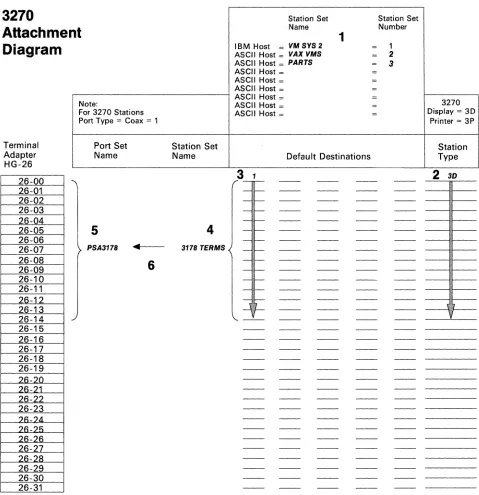
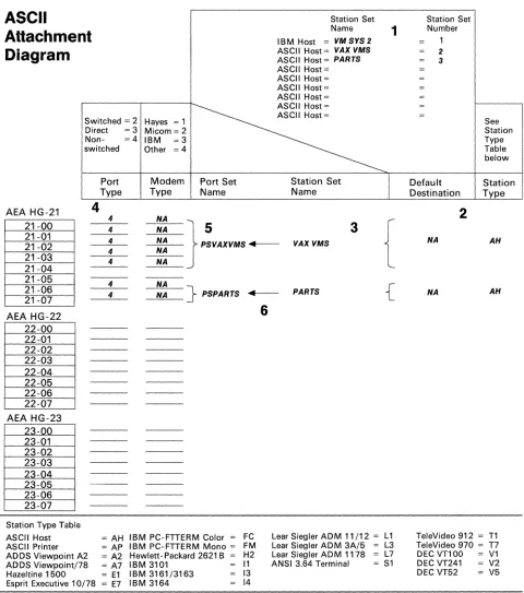
• Appendix A, "3174 Attachment Diagrams," provides worksheets to help with customization and site planning.
• Appendix B, "ASCII Emulation," provides more detailed information about Digital Equipment Company (DEC) VT100 Emulation, IBM 3101 Emulation and ASCII Printer Emulation.
Related Publications
IBM 3174 Publications
IBM 3270 Information Display System:
3174 Subsystem Control Unit Site Planning, GA23-0213
3174 Subsystem Control Unit Customizing Guide, GA23-0214
3174 Subsystem Control Unit Customer Extended Problem Determination,
GA23-0217
3174 Subsystem Control Unit Functional Description, GA23-0218
3174 Subsystem Control Unit Terminal User's Reference for Expanded Func-tions, GA23-0332
3174 Subsystem Control Unit Models 51R, 52R, and 53RUser's Guide,
GA23-0333
3174 Subsystem Control Unit Models 1L, 1R~ 2R, and 3R User's Guide,
GA23-0337
3174 Subsystem Control Unit Asynchronous Emulation Adapter Customer Setup Instructions, GA23-0341
Data Stream Programmer's Reference, GA23-0059
Other Publications on Asynchronous Communication
IBM 3101 Product Description, GA 18-2033
IBM 316113163 ASCII Display Station Description, GA18-2310
IBM 3162 ASClI Display Station Description
IBM 3164 Color Display Station Description, GA18-2317
IBM 5841 Modem Guide to Operations, GA27-3649
IBM 5842 Modem Guide to Operations, GA27-3638
Contents
Chapter 1. Asynchronous Emulation Adapter Overview . . . 1-1 Physical Description . . . 1-2 Model Support . . . 1-2 Functional Description . . . 1-3 Asynchronous Emulation Adapter . . . 1-3 3270 Terminal Emulation . . . 1-5 ASCII Terminal Emulation . . . . . . .. 1-10 ASCII Pass-Through . . . . . . .. 1-12 Modems . . . 1-14
Flow Control 1-14
Connection Management . . . 1-14 Security . . . .. 1-14 Control Unit Access Password . . . 1-15 Idle Time-Out . . . 1-15
Switched Disconnect Time-Out 1-15
Outage Notification . . . 1-15 Language Support . . . . . . .. 1-15 Performance Considerations . . . .. 1-15 Online Tests, Error Logs, and Alerts . . . 1-15 File Transfer (FTIERM) . . . 1-16
Chapter 2. Planning and Using Asynchronous Communications .. . . . .. 2-1 AEA Terminology and Concepts . . . 2-2 Station Sets . . . 2-4 Port Sets . . . 2-4 Planning and Setup Tasks . . . 2-5 Analyze Your Communication Requirements . . . 2-5 Create a System Specification . . . . . .. 2-5 Things to Do . . . . . . .. 2-6 Fill Out the 3174 Attachment Diagrams . . . 2-6 Order Communication Lines . . . 2-6 Subscribe to an Information Service . . . .. 2-6 Order EIA 232D cables . . . 2-7 Order Modems . . . 2-7 Order Test Equipment . . . 2-7 Prepare the Site . . . 2-7 Customize the 3174 for AEA Operation . . . 2-7 Set Up AEA Hardware . . . 2-7 System Checkout . . . 2-7 Phase 1 - Customer Setup and EIA 232D Cable Checkout . . . . . .. 2-8 Phase 2 - Customization and Modem Checkout . . . 2-8 Phase 3 - Operational Checkout . . . .. 2-8 Customization Overview . . . 2-10 Station Sets and Port Sets . . . 2-10
Chapter 3. Case Studies . . . 3-1 General Design Conventions . . . 3-2 Case Study Format . . . 3-2 ASCII Terminal Emulation Case Study . . . 3-3 System Description and Communication Requirements . . . . . . . .. 3-3 What We Have to Do . . . 3-3 Specific Design Qualifications 3-3
Hardware Requirements . . . 3-3 3174 Attachment Diagrams . . . 3-4 3270 Attachment Diagram . . . 3-4 ASCII Attachment Diagram . . . 3-6 Hardware Setup . . . 3-6 Customization Requirements . . . 3-8 AEA Configure Worksheet . . . .. 3-8 AEA Port Set Worksheet . . . 3-9 AEA Port to Port Set Map Worksheet . . . 3-10 AEA Station Set Worksheets . . . 3-11 AEA Default Destination Worksheet . . . 3-15 System Checkout and Operation . . . 3-15 3270 Terminal Emulation Case Study . . . 3-17 System Description and Requirements . . . 3-17 What We Have to Do . . . 3-17 Specific Design Qualifications . . . 3-17 Hardware Requirements . . . 3-17 3174 Attachment Diagrams . . . 3-18 ASCII Attachment Diagram . . . 3-18 Hardware Setup . . . 3-18 Customization Requirements . . . 3-20 AEA Configure Worksheet . . . . . . .. 3-20 AEA Port Set Worksheet . . . 3-21 AEA Port to Port Set Map Worksheet . . . 3-22 AEA Station Set Worksheets . . . 3-23 AEA Default Destination Worksheet . . . 3-26 System Checkout and Operation . . . 3-26 3270 and ASCII Terminal Emulation Case Study . . . .. 3-27 System Description and Requirements . . . 3-27 What We Have to Do . . . 3-28 Specific Design Qualifications . . . 3-28 Hardware Requirements . . . 3-28 3174 Attachment Diagrams . . . 3-29 3270 Attachment Diagram . . . 3-29 ASCII Attachment Diagram . . . 3-31 Additional Customizing Requirements . . . 3-31
Chapter 4. Modem and ASCII Terminal Setup Reference . . . 4-1 Modem Specifications and Setup . . . . . . .. 4-2 IBM 5841 and 5842 Setup . . . 4-2 Hayes SmartModem 1200 Setup . . . 4-3 Micom Data Modems . . . 4-5 ASCII Station Setup . . . 4-5
Chapter 5. EIA 232D Cabling Specification . . . 5-1 EIA 232D Cabling to Data Terminal Equipment (DTE) . . . 5-2 EIA 232D Cabling to Data Circuit-Terminating Equipment (DCE) . . . 5-3 Pin Assignments and Signal Description . . . " 5-4
Appendix A. 3174 Attachment Diagrams A-1
Appendix B. ASCII Emulation . . . 8-1 VT100 Emulation . . . . . . .. 8-2
Keyboard Map . . . 8-2 Caps Lock Key . . . 8-4 Typematic Keys . . . 8-4
CTRL Key . . . 8-4 8reak Key . . . 8-4 Function Keys . . . 8-4 Setup . . . 8-6 Indicator Line . . . 8-8 Host Data Streams . . . 8-8 3101 Emulation . . . 8-13 Keyboard Map . . . 8-13 Typematic Keys . . . 8-14 ALT key . . . 8-14 8reak Key . . . 8-14 Function keys . . . 8-14 Setup . . . 8-15 Indicator Line . . . 8-17 Host Data Streams . . . 8-18 ASCII Printer Emulation . . . 8-20
List of Abbreviations . . . X-1
Glossary . . . X-5
Index . . . X-17
Figures
1-1. 1-2. 1-3. 1-4. 2-1. 2-2. 3-1. 3-2. 3-3. 3-4. 3-5. 3-6. 3-7. 3-8. 3-9. 3-10. 3-11.
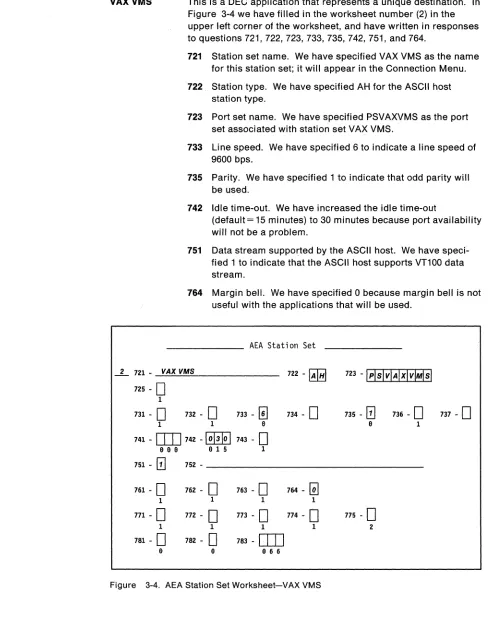
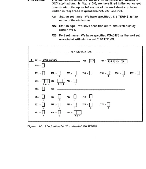
Overview of 3270 and ASCII Terminal Emulation . . . 1-4 3270 Terminal Emulation . . . 1-5 ASCII Terminal Emulation . . . 1-10 ASCII Pass-Through . . . 1-13 3270 Terminal Emulation Example . . . 2-2 ASCII Terminal Emulation Example . . . 2-4 ASCII Terminal Emulation-3270 Attachment Diagram . . . 3-5 ASCII Terminal Emulation-ASCII Attachment Diagram . . . 3-7 AEA Station Set Worksheet-VM SYS 2 . . . 3-11 AEA Station Set Worksheet-VAX VMS . . . 3-12 AEA Station Set Worksheet-PARTS . . . 3-13 AEA Station Set Worksheet-3178 TERMS 3-14 AEA Default Destination Worksheet-ASCII Terminal Emulation ... 3-15 Connection Menu . . . 3-16 3270 Terminal Emulation-ASCII Attachment Diagram . . . 3-19 AEA Station Set Worksheet-MVS SYSTEM A . . . 3-23 AEA station Set Worksheet-PC-FTTERM-COLOR 3-24 3-12. AEA Station Set Worksheet-PC-VT100 . . . 3-25 3-13. AEA Default Destination Worksheet-3270 Terminal Emulation ... 3-26 3-14. AEA Station Set Worksheet-ASCII HOST . . . 3-28 3-15. 3270/ASCII Terminal Emulation-3270 Attachment Diagram 3-30 3-16. 3270/ASCli Terminal Emulation-ASCII Attachment Diagram 3-32 5-1. EIA 232D-lnterface Cabling to a DTE (Terminal or Computer) 5-2 5-2. EIA 2320 -Interface Cabling to a DCE (Modem) . . . 5-3 A-1. 3270 Attachment Diagram . . . A-3 A-2. ASCII Attachment Diagram . . . A-5 8-1. VT100 Function Key Map . . . 8-5 8-2. VT100 Emulation Escape Sequences . . . 8-10 8-3. 3101 Emulation Escape Sequences . . . 8-19
Tables
4-1. IBM 584x Modem Switch Settings . . . 4-3 4-2. Hayes SmartModem 1200 Configuration Switch Settings . . . 4-4 4-3. Hayes SmartModem 1200 Register Settings . . . 4-4 5-1. 3174-to-DCE Connector Pin Assignments . . . 5-4 8-1. Notes on Escape Sequences . . . 8-11. 8-2. Notes on 3101 Setup Options . . . 8-16 8-3. Notes on the 3101 Indicator Line . . . 8-17
AEA Overview
Chapter 1. Asynchronous Emulation Adapter Overview
Physical Description . . . 1-2 Model Support . . . 1-2 Functional Description . . . 1-3 Asynchronous Emulation Adapter . . . 1-3 3270 Terminal Emulation . . . 1-5 ASCII Terminal Emulation . . . . ASCII Pass-Through . . . . Modems . . . . Flow Control . . . . Connection Management . . . .... . Security . . . . Control Unit Access Password . . . . Idle Time-Out . . . . Switched Disconnect Time-Out
Outage Notification . . . . Language Support . . . . Performance Considerations . . . . Online Tests, Error Logs, and Alerts . . . . File Transfer (FTTERM) . . . .
1-10 1-12 1-14 1-14 1-14 1-14 1-15 1-15 1-15 1-15 1-15 1-15 1-15 1-16
AEA Overview
The Asynchronous Emulation Adapter (AEA} feature consists of both hardware and microcode installed in the 3174 Subsystem Control Unit. This adapter expands the connection capability for IBM 3270 terminal~ (display stations or printers), allowing them to connect to American National Standard Code for Information Interchange (ASCII) hosts, and public data networks, as well as allowing ASCII display stations and printers to connect to IBM hosts.
Physical Description
Model Support
The AEA feature includes:
• An adapter card that contains a microprocessor, storage, and control logic • An input/output (110) panel with eight Electronics Industries Association (EIA)
232D connectors for modem or direct ASCII terminal or host connection • A diskette with microcode for the AEA
• A wrap plug for testing.
A second 1.2-megabyte (MB) diskette drive must be installed in the 3174 to support downloading of the operational microcode. This diskette drive may also be used for any other devices that require the downloading of microcode.
The AEA feature is supported in the following 3174 models: • Models 1L, 1R, 2R, and 3R:
A maximum of three AEAs can be installed in these 3174 models, providing a total of 24 asynchronous ports.
For Systems Network Architecture (SNA) control units, the maximum number of 3270 host addresses (including 3270 and ASCII terminals) is 184. For non-SNA control units, the maximum number of 3270 host addresses (including both 3270 and ASCII terminals) is 32.
Note: 3174 Models 1L, 1R, and 2R cannot have both the Asynchronous Emu-lation Adapter feature and the IBM Token-Ring Network 3270 Gateway feature.
• Models 51R and 52R:
One AEA can be installed in these models of the 3174, providing a total of eight AEA ports.
These ASCII attachments are in addition to the maximum of sixteen 3270 termi-nals available on the control unit.
Note: 3174 Models 51R and 52R cannot contain both the Asynchronous Emu-lation Adapter feature and the IBM Token-Ring Network 3270 Gateway feature. In addition, the AEA feature is not available in a 3174 Model 53R.
AEA Overview
Functional Description
This section contains a description of the following functional areas of AEA operation:
• Asynchronous Emulation Adapter • Modems
• Flow control
• Connection management • Security
• Languages supported • Performance considerations • Online tests, error logs, and alerts • PC File Transfer
• ASCII Display Host Addressable Printer
Asynchronous Emulation Adapter
The AEA supports full-duplex, character-mode, asynchronous transmission of 7-bit ASCII (ANSI1 3.4, 1977) data. One or two stop bits, and odd, even, mark, space, or no parity are supported. Autobaud detect and XON/XOFF, DTR, or CTS asynchro-nous flow controls are supported.
Each port provides an EIA 232D electrical interface and supports transmission speeds of 300, 600, 1200, 2400, 4800, 9600, and 19000 bits per second (bps) through modems over switched and nonswitched communication facilities or without modems via direct connection. The Asynchronous Emulation Adapter provides three major modes of operation:
3270 Terminal Emulation Allows ASCII terminals to emulate an IBM 3178 Display Station Model C2, 3279 Color Display Station Model 2A, or 3287 Printer Model 2 for connection to an IBM host.
ASCII Terminal Emulation Allows an IBM 3270 display station to emulate an IBM 3101 Display Station, or a Digital Equipment Corpo-ration (DEC) VT100, and allows an IBM 3270 printer to emulate an ASCII printer; 3270 terminals can thereby connect to ASCII hosts or public data networks.
ASCII Pass-Through Allows ASCII terminals to connect through the 3174 control unit to ASCII hosts or to public data networks.
1 American National Standards Institute
AEA Overview
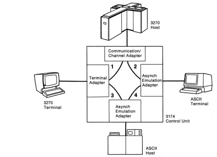
Figure 1-1 shows an overview of connection paths provided by the AEA. Only two AEAs are shown to illustrate distinctly the different connection paths; ASCII termi-nals and hosts may be connected to the same AEA.
Path 1 shows the traditional path between 3270 terminals and the 3270 host.
Path 2 shows that the AEA feature provides a connection between ASCII terminals and the 3270 host. This mode of operation is called 3270 terminal emulation. The AEA converts an ASCII protocol to the 3270 protocol, and sends the data through a 3270 host interface adapter to the 3270 host. Likewise, the AEA converts 3270 pro-tocol to an ASCII propro-tocol, and sends the data to the ASCII terminal. The AEA feature enables ASCII display stations to emulate (that is, to appear to the 3270 host to be) either an IBM 3178 Model C2 or an IBM 3279 Model 2A (four-color display). ASCII printers can emulate an IBM 3287 Model 2.
Path 3 shows that the AEA feature provides a connection between 3270 terminals and ASCII hosts. This mode of operation is called ASCII terminal emulation. The AEA converts 3270 protocol to an ASCII protocol, and sends the data to the ASCII host. Likewise, the AEA converts ASCII protocol to 3270 protocol, and sends the data to the 3270 terminal. The AEA feature enables 3270 display stations to emulate either an IBM 3101 or a DEC VT100 display station. IBM 3270 printers can emulate ASCII printers.
Path 4 shows that the AEA feature provides a connection between ASCII terminals and ASCII hosts, or public data networks. The AEA does not do any protocol con-version in this mode of operation. This mode of operation is called ASCII pass-through.
Terminal
1---+
Adapter3270 Terminal
Communicationl Channel Adapter
3270 Host
Asynch
Emulation .... - - - I I Adapter
Asynch Emulation
Adapter 3174
L---I.---r---'----~ Control Unit
ASCII Host
Figure 1-1. Overview of 3270 and ASCII Terminal Emulation
ASCII Terminal
[image:19.612.102.546.392.713.2]3270 Terminal Emulation
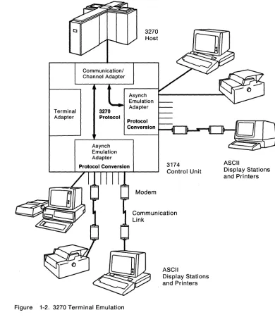
3270 Terminal Emulation
Figure 1-2 shows the flow of data between asynchronous terminals and an IBM 3270 host. Two AEAs are shown to illustrate a variety of connection possibilities.
Terminal Adapter
Communicationl Channel Adapter
3270
Protocol
Asynch Emulation Adapter
3270 Host
Asynch Emulation Adapter
Protocol Conversion
Protocol Conversion
Figure 1-2. 3270 Terminal Emulation
3174 Control Unit
ASCII
Display Stations and Printers
ASCII
Display Stations and Printers
[image:20.612.161.551.122.579.2]3270 Terminal Emulation
Display Stations: The following ASCII display stations are supported for 3270 Ter-minal Emulation:
• ADDS Viewpoint2 A2 and Viewpointl78
• ANSI 3.64 Terminals
• DEC VT52, VT100, VT220 (emu-lating a VT100), and VT241 (two colors only)
• Esprit4 Executive 10/78
• Hazeltine51500
• Hewlett-Packard6 2621 B • IBM PC/FTTERM Color? • IBM PC/FTTERM Mon08
• IBM 3101, 3151 (as a 3161 or a 3162 depending on the model), 316-1, 3162,3163 (supported as a 3161), and 3164 (supported for 3279 2A emulation - four colors) • Lear Siegler ADM 3A Dumb
Ter-minal9, ADM 5 Dumb Terminal, ADM 11, ADM 12, and ADM 1178 • TeleVide010 912 and 970.
IBM Personal Systeml2™ computers and IBM Personal Computers that meet the attachment requirements and that use a program that emulates one of the sup-ported display stations, are supsup-ported for 3270 Terminal Emulation.
Non-IBM personal computers that use a program that emulates one of the sup-ported display stations are supsup-ported. Non-IBM display stations that meet the requirements for attachment may connect to the AEA under the provisions of the IBM Multiple Supplier Systems Bulletin. To attach to the AEA, display stations must:
• Support a line speed of 300, 600, 1200,2400,4800,9600, or 19 200 bits per second (bps) on an EIA 232D interface (transmit and receive speeds must be equal)
• Operate in duplex, character mode • Support 7-bit code as defined by ANSI 3.4
• Support on XON/XOFF, DTR, or CTS flow control (a printer must be able to print at the full line speed if it does not use flow control)
2 Trademark of Applied Digital Data Systems, Inc.
3 A terminal that conforms to the ANSI 3.4 control sequences supported by the AEA. 4 Trademark of Esprit Systems, Inc.
5 Trademark of Hazeltine Systems, Inc. S Trademark of Hewlett-Packard Company.
? IBM PCIHOST File Transfer and Terminal Emulator Program Color (IBM PC/FTTERM Color)
8 IBM PC/HOST File Transfer and Terminal Emulator Program Monochrome (IBM PC/FTTERM Mono) 9 Lear Siegler, ADM, and Dumb Terminal are trademarks of Lear Siegler, Inc.
10 Trademark of TeleVideo Systems, Inc.
Personal System/2 is a trademark of the International Business Machines Corporation.
3270 Terminal Emulation
• Match one of the displays listed above with respect to: The control sequences used for 3270 emulation, such as:
Cursor positioning Line erase
Screen erase
Highlighting (if available) Status line control (if available) Printer port sharing (if available) Terminal setup and reset.
The keys used by the keyboard map to send codes or control sequences to the 3174
End-of-line (line-wrap) and end-of-screen (screen-wrap) conditions Screen size (must have at least a 24 by 80 - character screen).
The customer is responsible for determining whether the emulation program pro-vides identical function and operation as the emulated supported display station.
The ASCII terminal and its associated AEA port must be set up to operate with the same ASCII protocol parameters, such as line speed, parity, number of stop bits, data stream type, etc. With autobaud and autoparity the user will press a carriage return followed by a period and another carriage return; the AEA analyzes the received characters and adjusts the line speed and parity of the port to match the line speed and parity of the terminal.
For some terminals, the operator indicator status line is displayed on line 25. For other displays, users can type in an escape sequence to display the operator indi-cator status line on line 24. The operator indiindi-cator status line can be toggled on and off when the 24th line is used.
Keyboard: The user can choose a universal keyboard map or a specific keyboard map designed for each supported ASCII terminal; a keyboard map is a translation table that associates the keystrokes on the ASCII terminal keyboard to the corre-sponding, equivalent keystrokes on the 3270 terminal keyboard being emulated. For users of several different ASCII terminals, the universal keyboard map elimi-nates the need to remember each specific keyboard map. The specific keyboard maps minimize keystrokes for frequently used 3270 keyboard functions and take advantage of the ASCII keyboard's layout and nomenclature. Refer to the 3174
Ter-minal User's Reference for Expanded Functions for details on keyboard maps.
For greater efficiency, ASCII display station keyboards are not locked during a screen write. This capability enables keystrokes to be entered while the screen is being updated.
Note: If the 3174 is customized for RPQ 8K0808 keyboards, 3270 terminal emu-lation will not work for ASCII display stations.
Printer: The IBM 4201 Proprinter™ Proprinter II, 4202 Proprinter XL, 4207 Pro-printer X24, and 4208 ProPro-printer XL24 are supported for 3270 Terminal Emulation. The serial feature on these printers is required for them to attach to the AEA.
Proprinter is a trademark of the International Business Machines Corporation.
3270 Terminal Emulation
The general requirements for ASCII printers to be supported for 3270 Terminal Emulation (LU1 SNA character string [SCS] mode and LU3 3270 Information Display System data stream compatibility lDSC] mode) are as follows:
• Asynchronous (serial) transmission • EIA 2320 electrical interface • Duplex, character mode
• Seven-bit code defined by ASCII (ANSI 3.4, 1977)
• Equal transmit and receive speeds; the speed must be one that is supported on the emulation adapter
• Support of the maximum line length sent by the application program or local copy function
• Support of the required ASCII commands: Carriage Return (Control M; hex 00) Line Feed (Control J; hex OA) Bell (Control G; hex 07)
In addition:
• Carriage return must not generate a line feed, nor can a line feed generate a carriage return.
• The printer must not be dependent on any delay characters to allow mechan-ical motion.
• The printer must be ready to print; the AEA will not initialize an ASCII printer emulating a 3270 printer.
• If the printer does not support a flow control that is supported by the AEA (XON/XOFF, CTS, or DTR), it must be ready to print at the full speed of the line.
ASCII printers operating in 3270 Terminal Emulation can be used as host printers, shared printers, and local copy printers.
ASCII Display Host Addressable Printer: A printer attached to an auxiliary port on a display connected to a 3174 AEA port can be defined as a second logical unit (LU) on the 3174 AEA port. The display and its attached printer appear as two dis-tinct LUs to the host application(s). The host application(s) can communicate with both the display and the printer at the same time.
The following conditions apply to a display terminal with an attached printer. • A printer connected to an auxiliary port on a display must be defined to the
3174.
• Input from devices that are connected to the auxiliary port of a display is not explicitly supported; any such input is assumed to be for the display.
• Terminal users may suspend and resume the Printout to the systems auxiliary port by pressing a Suspend Print or a Resume Print key sequence.
3270 Terminal Emulation
• Only the following display terminals are enabled for attached printer operation: ADDS Viewpoint A2
VT101 (as a VT100) VT131 (as a VT100) VT220 (as a VT100) VT241
IBM 3151, 3161, 3162, 3163, or 3164 ASCII Display Stations Lear Siegler 11, 12, and 1178
IBM PC/FTTERM Color or Monochrome TeleVideo 970
Host Attachment: The IBM host is attached to the 3174 by one of the host attach-ment interfaces available on the 3174; the host attachattach-ment interface can be the Channel Adapter, the Communication Adapter, or the Token-Ring Adapter (3174 ModeI3R).
At customization, a specific host destination (usually the IBM host) can be assigned to the ASCII display stations. If the host destination is not specified, the display station user is presented with the Connection Menu, from which a host attachment can be selected.
ASCII Terminal Emulation
ASCII Terminal Emulation
Figure 1-3 shows the flow of data between 3270 terminals and an asynchronous (ASCII) host.
Communication/ Channel Adapter
3270 Host
Asynch Emulation Terminal
Adapter 3270 Adapter
3270
Display Stations and Printers
Protocol
Asynch Emulation Adapter
Protocol Conversion
Figure 1-3. ASCII Terminal Emulation
1-10
Asynchronous Emulation Adapter: IntroductionModem 3174 Control Unit
Communication Link
o
[image:25.612.65.517.95.718.2]ASCII Terminal Emulation
Display Stations: Any IBM 3270 Control Unit Terminal (CUT) display station with a 1920-byte or greater buffer, or an IBM 3270 PC in CUT mode, can emulate an IBM 3101 or a DEC VT100 display station.
Nole: In ASCII-emulation mode, some keystroke sequences are generated differ-ently on an IBM PC, PS/2, 3270 PC, or 3194 Display Station, that uses an IBM 3270 terminal emulator. Examples of this are the ASCII control code key sequences that are emulated using ALT followed by another key.
ASCII display emulation provides the following support: • Duplex character mode data transmission
• 24 lines at 80 characters per line • Operator indicator line
• Mapping of the 3270 display keyboard • Data stream mapping
• Function keys • Typematic keys • ALT key (3101) • Caps lock key (VT100) • CTRL key (VT100)
• Break key (long or short for VT100)
• ASCII display keyboard setup options that have equivalent 3270 keyboard setup functions
• Specification via control unit customization of terminal setup options that can be supported on the 3270 display.
IBM 3101 functions and keys not supported are:
• Half-duplex transmission and functions associated with half-duplex operation • Block mode and keys active in block mode
• Reverse video • Local mode • Transparent mode
• Auxiliary printer port and associated keys.
DEC VT100 functions and keys not supported are:
• Keys associated with setup mode that do not have equivalent 3270 keys • Interlace mode
• Screen mode (reverse and normal)
• Select character set (see Table B-1 on page B-10) • Invoke confidence test
• Attached printer and Hard Copy key • Set column mode to 132
• Smooth scroll.
Keyboard: The IBM Typewriter, APL, and Text keyboard types are supported through special keyboard maps for the IBM 3101 and the DEC VT100 display stations; a keyboard map is a translation table that associates the keystrokes of one keyboard to the corresponding, equivalent keystrokes of another keyboard. In this case, the keyboard maps show what keystrokes on a 3270 keyboard are equiv-alent to those on either a 3101 or a VT100 keyboard. Refer to the Terminal User's
Reference Guide for Expanded Function for additional details on mapping.
ASCII Pass-Through
Notes:
1. Converged (122-key) and IBM Enhanced keyboards need a numeric keypad. 2. Keyboard modifications made using the Modified Keyboard Procedure are not
supported.
3. RPQ 8K0808 keyboard is not supported.
Printer: The IBM 3262 Models 3 and 13,3268 Model 2, 3287 Models 1 and 2, and 4224 Models 210 and 202 are supported for ASCII printer emulation. ASCII control sequences for the following functions are supported: line feed, form feed, carriage return, bell, and tab-skip to the next multiple of 8 characters. The 3270 printer in this mode can be used only as a host printer, and not as a local copy printer.
Host Attachment: ASCII host attachment can be provided through any AEA port via customizing. ASCII host links can support only one session at a time; when all ports are in use, requests for sessions are not honored until a session ends and a port is available.
A display user can attach to, or change, hosts by requesting the Connection Menu and selecting a host from the list displayed. The Connection Menu also provides host availability status information. If a path is available to that host, a connection will be made.
If Multiple Logical Terminal (MLT) support is available, a 3270 display station user can interact with, and remain connected to, up to five host sessions. The host ses-sions can be to a single IBM host, one or more ASCII host(s), or both. Access to hosts is made through either the Connection Menu or the Default Destination pro-cedure (refer to the 3174 Customizing Guide).
Each MLT session using the connection to an IBM host requires a session address; a session with an ASCII host does not need an IBM host address. The host con-nection and associated session address are defined during 3174 customizing. A SNA 3174 supports up to 184 session addresses; a non-SNA 3174 supports up to 32 session addresses. Users access these MLT sessions by using a Change Screen key sequence. This key sequence causes the display screen and keyboard owner-ship to be transferred to the next session in a round-robin manner. Host access to a particular session is processed independently of the other session states. Refer to the 3174 Terminal User's Reference for Expanded Functions for more informa-tion on ML T operainforma-tion.
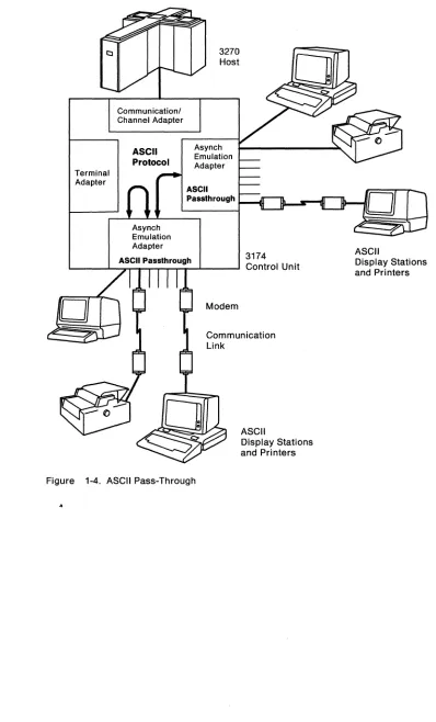
ASCII Pass-Through
Figure 1-4 on page 1-13 shows the flow of data between ASCII terminals and an ASCII host.
The AEA can provide the connection between an ASCII terminal and an ASCII host. At customizing, a specific ASCII host destination can be assigned to the ASCII display stations. If the host destination is not specified, the display station user is presented with the Connection Menu, from which a host attachment can be selected.
Flow controls supported by the adapter will prevent potential data overruns if sup-ported by the~host connection. If an overrun does occur, the session is discon-nected, and a message is sent to the display station operator. Error checking is the responsibility of the ASCII host.
Terminal Adapter
Communication! Channel Adapter
ASCII Protocol
Asynch Emulation Adapter
3270 Host
Asynch Emulation Adapter
ASCII
P8ssthrough
3174
L..-_ _ -'-_A.."S"TC_lrl P...,8,...S"Ts_th,...ro..,u_grh---l _ _ - - l Control Unit
Modem
Communication Link
ASCII
Display Stations and Printers
Figure 1-4. ASCII Pass-Through
..
ASCII Pass-Through
ASCII
Display Stations and Pri nters
[image:28.612.147.545.69.727.2]AEA Overview
Modems
Flow Control
The AEA feature supports nonswitched line, switched line, and limited-distance modems that provide duplex asynchronous operation and equal transmit and receive speeds, and that conform to EIA 232D specifications. The AEA feature also supports auto-call 11 modems that conform to the EIA 232D specifications and to the IBM Attention Command Set (AT), the Hayes12 AT command set, the Micom13 auto-dial procedure, or the AEA manual calling14 requirement.
Transmitter on/transmitter off (XON/XOFF), data terminal ready (DTR), and clear to send (CTS) asynchronous flow controls are supported. XON/XOFF flow control is the only flow control supported for switched lines. ASCII control character DC1 is used by the terminal to signal the host to start transmitting data. ASCII control character DC3 signals the host to stop transmitting data. Nonswitched lines can use XON/XOFF or DTR flow control. Direct lines can use XON/XOFF or CTS flow control.
Connection Management
Security
The user connects to IBM and ASCII hosts through the Connection Menu or the Default Destination procedure as specified during customizing. Switched-line con-nections to ASCII hosts can be made via dial digits stored in the control unit or entered from the display keyboard. Connections are held until the next connection is established. With MLT, each connection is held until the user terminates that connection. Messages appear on the display station's screen in the event of a con-nection outage.
The security features provided with AEA support are Control Unit Access Pass-word, Idle Time-Out, and Switched Disconnect Time-Out. The AEA feature also supports SNA connection outage notification.
Security cannot be provided for host subsystems or applications (such as the Infor-mation Management System [IMS)) that retain data between sessions in the expec-tation that the same logical unit will come into session again.
If sensitive data is sent over external communication facilities, an encryption scheme, such as that provided by the EncryptlDecrypt feature, should be used.
11 An auto-call modem accepts dial digits from the AEA over the data leads. In AEA operation, auto-call is a feature whereby dial digits (an ASCII host phone number) are stored in the 3174 control unit. These digits are sent to the auto-call modem when the user requests a connection to the ASCII host.
12 Trademark of Hayes Microcomputer Products, Inc.
13 Trademark of Micom Systems, Inc.
14 In AEA operation, manual calling means that the terminal user enters the modem commands and dial digits from the keyboard in order to initiate a connection to an ASCII host.
AEA Overview
Control Unit Access Password
Idle Time-Out
A control unit access password can be specified at customization. The AEA will prompt any display user that uses a switched port for the password. The 3174 will break the connection if the user supplies the wrong password.
Idle Time-Out (ASCII ports only) can be specified at customization. The main objective of this time-out is to terminate sessions that have been inactive for the specified time, thereby avoiding excessive charges for connections through the telephone network. However, the Idle Time-Out also reduces the chance of someone using a session that has been left unattended or has not been properly terminated.
Switched Disconnect Time-Out
Outage Notification
The Switched Disconnect Time-Out pertains only to non-SNA applications. Some non-SNA applications have a time-out for inactive or non-communicating sessions; a session is terminated by the application if the time of inactivity exceeds the time-out. When a switched connection breaks, the 3174 disallows the affected port access to the IBM host for the duration of the Switched Disconnect Time-Out (speci-fied at customization); this time-out should exceed the host's inactive session time-out, and thereby allow the host application to terminate the session before the port can be used again for 3270 Emulation. However, the port can be used for ASCII Terminal Emulation and ASCII Pass-Through. By blocking access to the IBM host, the Switched Disconnect Time-Out prevents any possibility of unauthorized access to an IBM host session.
When a switched connection to a 3270 SNA host breaks, SNA control units send an UNBIND request to the 3270 host; the host application can then terminate the session.
Language Support
Only
u.s.
English screens and keyboards are supported. Therefore, the 3174 must be configured for U.S. English 3270 host applications.Performance Considerations
Response time depends on many variables, including the number and types of ter-minals attached, the transaction rates and contents, and system parameters such as response unit (RU) lengths and pacing. An AEA can handle about 5000 bytes per second (burst input rate) before character overruns occur.
Online Tests, Error Logs, and Alerts
Online tests provide AEA status and error information. The Asynchronous Emu-lation Adapter online test (Test 12) contains a set of five selectable options for testing AEA ports and configuring modems. Refer to the 3174 User's Guide for detailed information.
Errors relating to asynchronous station operation are logged, alerts are sent to the host, and network statistics are gathered in the same way as for 3270 terminals.
File Transfer (FTTERM)
The Asynchronous Emulation Adapter supports file transfer between the IBM Host and an IBM PC running the IBM PC/HOST File Transfer and Ter-minal Emulator Program (FTTERM). This program gives the user of an IBM PC full-screen 3270 terminal emulation and file transfer capability when operating in protocol conversion mode with the 3174.
1-16
Asynchronous Emulation Adapter: Introduction-Planning and Using Asynchronous Communications
Chapter 2. Planning and Using Asynchronous
Communications
AEA Terminology and Concepts . . . 2-2 Station Sets . . . 2-4 Port Sets ... : . . . 2-4 Planning and Setup Tasks . . . 2-5 Analyze Your Communication Requirements . . . 2-5 Create a System Specification . . . .. 2-5 Things to Do . . . 2-6 Fill Out the 3174 Attachment Diagrams . . . 2-6 Order Communication Lines . . . 2-6 Subscribe to an Information Service . . . . . . .. 2-6 Order EIA 232D cables . . . 2-7 Order Modems . . . 2-7 Order Test Equipment . . . 2-7 Prepare the Site . . . 2-7 Customize the 3174 for AEA Operation . . . 2-7 Set Up AEA Hardware . . . 2-7 System Checkout . . . 2-7 Phase 1 - Customer Setup and EIA 232D Cable Checkout . . . . . . .. 2-8 Phase 2 - Customization and Modem Checkout . . . 2-8 Phase 3 - Operational Checkout . . . 2-8 Customization Overview . . . 2-10 Station Sets and Port Sets . . . 2-10
AEA Terminology and Concepts
To plan and set up a communication network, you should be familiar with network components and configurations. Also, you must know the specific terminology that is used in AEA customization and operation. Under "AEA Terminology and
Concepts" are examples of 3270 and ASCII Terminal Emulation with the basic com-ponents, required for data communication. These examples should help you under-stand the terminology, concepts, and functions of asynchronous communication with the AEA feature.
In addition, this chapter describes the major planning and setup tasks required to customize, set up, and operate the 3174 Subsystem Control Unit with the Asynchro-nous Emulation Adapter (AEA) feature. A customization overview is also provided.
AEA Terminology and Concepts
The first example (see Figure 2-1) shows a 3270 Terminal Emulation configuration in which a remote ASCII terminal is connected over telephone lines to an IBM host. The components of the configuration are labeled, and the specific AEA customizing-terms that apply to these components are shown below, in bold.
Communication Line EIA 2320
I
SWir
edStation
Figure 2-1. 3270 Terminal Emulation Example
AEA
Port
Destination (Station)
The ASCII terminal is called a station. In general, a display station, printer, or host (IBM or ASCII) involved in asynchronous communication through the AEA is called a station. In AEA customizing, ASCII terminal stations are identified by a range of characteristics, including station type (such as IBM 3101, DEC VT100, Hewlett-Packard 2621 B), destination (in this case, the IBM host), flow control type (in this case, Xon/Xoff), line speed, and parity.
Modems convert the digital signals from terminals or computers to analog commu-nication signals at one end of the line, and convert the analog commucommu-nication signals back to digital signals at the other end of the line. In AEA customizing, the modem attached to an AEA port is identified by its modem type; the four modem type designations are Hayes, Micom, IBM, and Other. Limited-distance modems (LDM) do not have a modem type designation. The Hayes, Micom, IBM, or equiv-alent auto-call modems are required only for dialing out from the 3174 to an ASCII host or public data network. In Figure 2-1, an auto-call modem would be useful at the terminal end of the line; at the 3174 end of the line, an auto-call modem is not required to process calls coming in to the 3174. The modem attached to the remote ASCII terminal must use the same speed and modulation technique as the associated modem attached to the AEA port. Also, the remote modem's type is not relevant to AEA configuration.
AEA Terminology and Concepts
The Communication line transmits data between modems. In this example, the communication line is a switched line. Switched lines (also called dial lines) use the same equipment and transmission lines that are used for voice (telephone) communication. A connection must be established between the terminal and the host before data can be transmitted. To establish a connection with the IBM host, the remote ASCII terminal user must dial (call) the 3174 just as with voice commu-nication. A user dials the 3174 phone number either by using a telephone con-nected to the nearby modem, or by using a communication application program and either selecting the number from a automatic call directory or entering the dial digits at the keyboard.
The 3174 then makes the IBM host connection, either immediately or after selection from the Connection Menu.
ASCII terminals can also be connected to the 3174 either directly or via
non-switched lines. In Figure 2-1 on page 2-2, if the ASCII terminal is no more than 15
meters (50 feet) away from the 3174, it can be connected directly to an AEA port; the two modems and the communication line are not needed for direct connection.
Unlike switched lines, nonswitched lines (also called leased lines or dedicated lines) do not require dialing to establish communication; the line is permanently connected instead of being routed through switching equipment.
The user should be aware that for nonswitched connections the AEA does not determine whether the connecting device is present or not. While this provides a more flexible interface, connections are sometimes made to nonexisting or powered-off devices. For ASCII host lines, if the user gets a nonswitched con-nection where the ASCII host is powered off or not connected, the characters will not be echoed (the ASCII host is responsible for character echoing). The user should return to the Connection Menu, disconnect, and try the connection again. This time the AEA will try another host line if one is defined and available.
In this example, an AEA port connects a modem to the 3174. In AEA customizing, ports are identified by their port type; the port type reflects the kind of communi-cation line or connection supported between the terminal and the 3174; the port types that can be used by ASCII stations are designated Switched, Direct, and
Non-switched. The AEA port type in Figure 2-1 on page 2-2 is a switched port.
In general, a destination is a host to which a terminal user has access. A default
destination can be specified at customizing; the default destination is the host to
which an ASCII terminal is connected when the user calls into an AEA port on the 3174. If a default destination is not specified, or if the default destination cannot be connected, the user is presented with a Connection Menu that consists of a list of host destinations from which the user can select a particular host or application.
The second example (see Figure 2-2 on page 2-4) shows an ASCII Terminal Emu-lation configuration in which a 3270 terminal is connected to a remote ASCII host. The components of the configuration are labeled, and the specific AEA customizing terms that apply to these components are shown below, in bold; only those compo-nents that differ from the 3270 Terminal Emulation example are described.
AEA Terminology and Concepts
Station Sets
Port Sets
EIA 2320
Destination (Station)
Communication Line
Figure 2-2. ASCII Terminal Emulation Example
EIA 2320
Port Port
Station
Destination (Station)
In AEA customizing, a 3270 terminal involved in asynchronous communication is also called a station. In AEA customization, 3270 terminal stations are identified by
their station type (display station or printer) and their destination configuration.
In AEA customizing, the port type of coax is designated for Terminal Adapter (TA) ports that connect 3270 terminal stations.
The modem attached to an AEA port used for calling out to an ASCII host over switched lines must be a Hayes, Micom, IBM, or equivalent auto-call modem.
In general, a destination is a host to which a terminal user has access. A default destination can be specified at customizing; the default destination is the host to
which a 3270 terminal station is connected when the user switches on the terminal, or toggles the NormallTest switch. If a default destination is not specified, the user is presented at connection time with a Connection Menu that consists of a list of
host destinations from which the user can select a particular host or application. In this example, IBM host could be the default destination; the ASCII host would then have been reached through the Connection Menu.
In many instances, much, of the information about an individual station is the same for a group of stations. Customizing provides a way to assign stations of the same type and destination to a station set and to assign station characteristics on a "set"
basis. All stations in a station set have the same terminal type and share the same characteristics. This customizing feature is designed to expedite the customizing of stations. Refer to "Customization Overview" on page 2-10 for more information.
As with station sets, much of the information about ports is the same for a group of ports. Customization provides a way to assign ports of the same type to a port set
and to assign port characteristics on a "set" basis. All ports in a port set provide access to the same station sets, and have the same port type and modem type. This customizing feature is designed to expedite the customizing of both AEA ports and those Terminal Adapter ports involved in asynchronous communication; it is
also the basis for setting up port pools. A port pool is a group of ports (a port set)
that offers multiple access points to the same resource. When the control unit receives a request to connect to a host, it scans the port set for a nonbusy (avail-able) port. If one is found, it is selected as the port through which the connection is processed. Refer to "Customization Overview" on page 2-10 for more information.
Planning and Setup Tasks
Planning and Setup Tasks
You must coordinate customizing and site planning activities. Those responsible for customizing the 3174 and for site planning must plan and implement their activ-ities together. Each must be aware of the function and purpose of the addition of the AEA feature.
Analyze Your Communication Requirements
You must identify which 3270 and ASCII stations attach to the 3174. In addition, you must decide how the ASCII stations will be connected to the 3174; ASCII stations can be connected either directly or through switched (dialed) or nonswitched tele-communication lines.
When choosing what kind of lines to use, consider that although auto-call modems are more expensive than ordinary modems, switched lines requiring auto-call modems are less expensive to rent and use than nonswitched lines. Over time, therefore, the expense of auto-call modems will be recovered by the savings real-ized on switched line costs.
Nonswitched lines are used to provide immediate access to a dedicated resource and to provide users with more reliable data communication. Nonswitched lines may be conditioned by the common carrier (the company that supplies communi-cation services) to reduce transmission errors and signal distortion, and to increase the speed capability of the line. Switched lines cannot be conditioned.
You must carefully evaluate your communication requirement~ when deciding on switched or nonswitched lines.
Remember that each asynchronous communication line can support only one session at a time. Therefore, if you have eight users of an ASCII host, and they all need to be connected all day to the same resource, your subsystem will require eight communication lines to that resource. This may be an unlikely circumstance, so you will need to do a traffic analysis to compute how many lines are required to support the users of a particular resource. For these eight users, you would need to evaluate the amount of connect-time per user per hour. You may find that three or four AEA ports are sufficient to achieve a very low probability that users will encounter an al/ ports busy condition.
Create a System Specification
Planners must work from an overall 3174 subsystem specification or layout plan, and they must work together. You should provide such a subsystem specification that will consist of 3174 Attachment Diagrams that identify all the attached 3270 (synchronous) and ASCII (asynchronous) displays, printers, and hosts. Provided in Appendix A are sample 3270 and ASCII Attachment Diagrams that you should copy, fill out, and give to your subsystem's planners. The diagrams account for a 3174 control unit that has up to thirty-two 3270 devices connected to the Terminal Adapter (direct-attached or through a multiplexer), and up to 24 ASCII devices (local and remote terminals or hosts). These diagrams provide much of the infor-mation required to fill out customization worksheets.
Planning and Setup Tasks
Things to Do
You can proceed to the tasks below after you have:
• Identified all the 3270 and ASCII attachments that will use the AEA feature • Resolved your data communication requirements
• Ordered the AEA feature.
Skip any tasks that do not pertain to your situation. You may want to check off each item as you complete it.
Copy and fill out the 3174 Attachment Diagrams (Appendix A) and give copies to those responsible for customizing the 3174 and preparing the site.
Order communication lines.
Subscribe to an information service. Order EIA 2320 cables.
Order modems. Order test equipment. Prepare the site. Customize the 3174.
Set up AEA hardware (when not installed at the IBM facility). Check out the system - Phase 1 (3174 hardware checkout). Check out the system - Phase 2 (customization checkout). Check out the system - Phase 3 (operational checkout).
Each item in the list is discussed in the following paragraphs.
Fill Out the 3174 Attachment Diagrams
The 3174 Attachment Diagrams are provided so that you can identify all the 3270 and ASCII displays, printers, and hosts that will be connected to the 3174 control unit. Follow the instructions that accompany each attachment diagram, and use the completed attachment diagrams to complete customizing and site planning worksheets.
Order Communication Lines
Contact your communication service (either the telephone company or your in-house communication department), and order the number and kind of communi-cation lines that meet your data communicommuni-cation requirements.
Subscribe to an Information Service
Information Services advertise in many trade magazines and journals; call the service and request a subscription. They will provide you with the resource phone number, a user 10 and password, and asynchronous communication protocol con-figuration information. This information will include such items as line speed, parity, number of stop bits, and host data stream type (VT100 or 3101). You will use this information when customizing the AEA ports that will access this information service.
Planning and Setup Tasks
Order EIA 232D cables
Order Modems
IBM does not provide EIA 232D cables with the AEA feature. You must order or assemble these cables. The cable's wiring must conform to the cabling specifica-tion described in Chapter 5, "EIA 232D Cabling Specificaspecifica-tion" on page 5-1. Make sure that your vendor provides cables that match this specification. Refer to 3174
Site Planning for additional information.
For auto-dialing out from the 3174 over switched lines, use Hayes, Micom, IBM, or equivalent intelligent modems. The documentation provided with these modems describes how to configure the modem for your specific operations. For answering calls from remote ASCII terminals, ordinary switched modems can be used. Refer to "Modem Specifications and Setup" on page 4-2 for modem specifications and configuration switch settings. For nonswitched connections over in-house wiring, limited-distance modems can be used.
Order Test Equipment
Prepare the Site
The following equipment may be needed to monitor or test AEA operation: • Test headset or test telephone to check telecommunication lines to remote
resources.
• Datascope and a break-out box to examine EIA 232D leads.
• EIA connector gender changer. To run EIA 232D cable wrap tests with the wrap plug supplied with the AEA feature, you may need an EIA connector changer that changes the gender of the end of the cable.
Refer to 3174 Site Planning for such details of site preparation as modem power and equipment rack space requirements. Plan also to terminate the telecommuni-cation lines somewhere near the modems.
Site planning worksheets must be filled out in accordance with the 3174 Attachment Diagrams.
Customize the 3174 for AEA Operation
Some of the major customizing activities required for AEA operation are described under "Customization Overview" on page 2-10. Refer to the 3174 Customizing
Guide for detailed information. The customization worksheets must be filled out in accordance with the 3174 Attachment Diagrams.
Set Up AEA Hardware
System Checkout
The 3174 must be accessible from the front and back to install the AEA, the back panel(s), and a ground strap. Customer setup and checkout instructions are pro-vided with the AEA feature.
System checkout consists of three phases: 1. Customer setup and EIA 232D cable checkout 2. Customization and modem checkout
3. Operational checkout.
Planning and
SetupTasks
Phase 1 - Customer Setup and EIA 232D Cable Checkout
The steps to take in Phase 1 are:
1. After hardware setup is completed, run offline diagnostics (Alt 2 IML and Alt 1 IML tests) as described in the customer setup instructions that accompany the AEA feature. These tests verify the proper operation of the 3174 and the AEA.
2. Attach EIA 2320 cables to the AEA ports.
3. Check the continuity of EIA 2320 cables; for cables wired for connection to a modem, the wrap plug is attached to the end of an EIA 2320 cable,' and ALT 1
IML wrap tests are run on the selected AEA port2 (refer to the 3174 User's Guide for test procedures). The procedure should be repeated for each such
cable. You should repair or replace any cable attached to a port that failed a wrap test and run the test again.
Phase 2 - Customization and Modem Checkout
The steps to take in Phase 2 are:
1. Connect EIA 2320 cables to modems, limited-distance modems, or "null modems."3
2. Connect communication lines to the modems.
3. Connect ASCII stations to the other end of the communication line.
4. IML the 3174 with customized microcode.
5. Configure and test modems using online test 12 (refer to "Modem Specifica-tions and Setup" on page 4-2 and the 3174 User's Guide for more information).
Phase 3 - Operational Checkout
In this phase, with all stations attached and the 3174 IMLed, exercise normal 3270
communications and any AEA modes of operation that apply.
The steps to take in Phase 3 are:
1. Sign on from 3270 display stations, and try to access the IBM host. This step verifies normal, IBM terminal/computer operations.
2. If applicable, switch on a directly attached ASCII display station, and check for the Connection Menu4 , terminal type prompt, or IBM host screen, whichever applies. (Press carriage return, or press carriage return, 'period', then press carriage return again.)
Try to access the IBM host; communication between an ASCII terminal and an IBM host exercises 3270 Terminal Emulation.
, To run EIA 2320 cable wrap tests with the wrap plug supplied with the AEA feature, you may need an EIA con-nector gender changer that changes the gender of the end of the cable.
2 Wrap tests work only on cables wired for connection to modems; wrap tests do not work on cables wired for direct
connection of terminals or computers.
3 A null modem is a device with two 25-pin O-shell connectors that attaches to the station end of a standard, straight-through, pin-for-pin EIA 2320 cable. The null modem does the crossing-over of the appropriate EIA 2320 leads required for the direct connection of a terminal or computer to an AEA port (see Chapter 5, ,"EIA 2320 Cabling Specification" on page 5-1).
4 Refer to the 3174 Terminal User's Reference for Expanded Functions for Connection Menu procedures.
Planning and Setup Tasks
3. From a 3270 display station (if ASCII Terminal Emulation is configured), request the Connection Menu4 (if necessary), and verify that the IBM and ASCII
hosts are listed. Try to access an ASCII host.
4. Request a connection to the IBM host from a supported remote ASCII display station, or one configured to emulate a supported station. Communication between the ASCII terminal and the IBM host exercises 3270 Terminal Emu-lation and all the hardware components of remote access.
5. If applicable, request a connection to an ASCII host from an ASCII display station to exercise ASCII Pass-Through.
Customization Overview
Customization Overview
The control unit requires information about the stations attached to the AEA. Unlike coax-attached stations, most of this information must be provided through customizing because ASCII stations do not have a standardized way of identifying themselves to the control unit at connection time. Information about the AEA ports, their use by 3270 stations, and the ASCII stations must be provided to the control unit through customizing.
Station Sets and Port Sets
In many instances, much of the information about stations and ports is the same for groups of stations and ports. Customizing provides a way to put stations and ports into station sets and port sets, respectively, and to assign station and port charac-teristics on a "set" basis. All members of a set share the same characcharac-teristics. This customizing feature is designed to expedite the customizing process; it is also the basis of defining port pools.
Examples:
1. Eight ports on a single AEA are to be used to connect to IBM 3163 display stations over in-house lines running at 9600 bps. The display stations can be grouped into a station set that defines the common station type, line speed, parity, default destination, and other station characteristics. The ports can be grouped into a port set that defines the common port type as nonswitched. Lastly, the station set would be assigned to the port set.
2. Twelve ports (eight on one AEA, four on another) are to be used to provide access to a public data base through auto-dialing IBM modems. The ASCII host that has the public data base would be a station set that defines the host's attributes, such as the phone number for the host, line speed, parity, and flow control type. The ports can be grouped into a single port set (named, for example, "CALL OUT") that defines the common port type as switched, and the common modem type as IBM.
3. If VT100s, 3163s, and PCs emulating 3101s .all called in to a pool of 20 AEA ports, they would be defined in three station sets all pointing at the same port set: "CALL IN."
4. A switched port set may be used for both incoming calls from displays and for outgoing calls to hosts. The port sets, CALL OUT and CALL IN (in examples 2 and 3), could be combined into one port set, "IN OUT".
Defining port sets and station sets for fixed connections (coax, nonswitched, or direct ports) is usually straightforward: ports that connect stations with the same attributes5 are assigned to a port set, and stations of the same type are described in a single station set that is assigned to that port set.
Note: Separate port sets must be defined for ASCII host station sets and ASCII ter-minal station sets that are connected to the AEA either directly or over non-switched lines.
5 For customizing purposes, two stations have the same attributes if all the station set questions have the same answers.
Switched connections offer a wider range of possible configurations; this makes customization for switched connections more complex. Again, stations that have the same attributes are defined in a station set. Several different station sets can be assigned to a single port set. The port set thus becomes a pool of ports that can be used by stations of different types.
When defining port sets, remember that the control unit distinguishes the station sets within a port set by their station type. This has several specific implications:
• Display station sets assigned to one port set must have different station types. When a display station calls in, the control unit determines its station set by the user's response to the station type prompt.
• Display station sets assigned to one port set must have identical attachment parameters (speed, parity, stop bits); they must all use the same speed/parity or autobaud so that the control unit knows what to expect when stations call in. • ASCII Host Station sets assigned to one port set do not require identical
attach-ment parameters (speed, parity, or stop bits) within a port set.
• Printers and display stations must be in different port sets. When a call
arrives, the control unit must know whether the call is made from a display or a printer. The printer cannot respond to a station type prompt.
• A display with an attached printer is treated as a Display; how